


Concorde question

Join Date: Feb 2009
Location: Jungles of SW London
Age: 77
Posts: 354
Likes: 0
Received 0 Likes
on
0 Posts
I know exactly what you mean Clive and ordinarily I would agree with someone with vastly greater knowledge and experience, but it just looks too.........'classy' for a drain. The aperture is a rounded rectangle, very wave guide in nature and that vane is beautifully made, whatever it was made of. The only thing is, I'm a bit concerned the aperture is not covered in some way.
Somebody, somewhere must know what it is and now I'm fascinated.
Somebody, somewhere must know what it is and now I'm fascinated.

Moderator
engineers live their lives in an atmosphere of mutual jovial insult
Indeed, good sir. Having been exposed throughout a lifetime to various disciplines, including aerodynamics (djpil and I shared adjoining desks under AW's watchful glare in an earlier life at the Bend), I invariably upset various parties from time to time when I line select and execute the wrong set of social mores for the company in question.
Oh well, it's been anything but a boring life.
Join Date: Jan 2011
Location: South Manchester
Posts: 15
Likes: 0
Received 0 Likes
on
0 Posts
One of the guys on the Save the TU144 Facebook page says that the thing in that picture on the TU144 is connected to the Air Conditioning.
There is also a TU144 website now. Format donated by Gordons ConcordeSST
TU-144 SST - Flying Forever on the Internet
There is also a TU144 website now. Format donated by Gordons ConcordeSST
TU-144 SST - Flying Forever on the Internet
reverser incident 70s
hi guys, thanks for a very informative thread.
In the mid 70s I lived in a thatch cottage 31nm west of LHR at the bottom of a hill in the Thames valley.
One particularly grotty dark autumn evening our cottage started shaking, I rushed out into the dark expecting to see a car crash but realised it was a low flying aircraft. (I wasn't a stranger to low aircraft noise as we were in the Greenham Common circuit and the F111 had been based here when Upper Heyford was resurfaced).
I later read that droop snoop had an engine go into reverse in cruise.
The subsequent report in the horror comic was of it's following take off when it happened again on rotate.
What I remembered was some sort of award to engines or probably the whole crew and that she didn't get above three thou until crossing the Bristol coast.
questions...
Was it a simple electrical failure?
Was there any protection to stop it happening again?
Was there a significant speed loss when it happened?
Was there a problem with the adjacent engine?
Flying questions.
What was the engine out climb procedure?
Was there another double engine failure procedure as on the iron duck with immediate fuel dumping?
Was it just a coincidence that the flight was routed outside of CAS but along the Thames valley avoiding the high ground to the north and Membury mast?
Thanks
sorry if it has already been covered but have only got through to page 50...
Join Date: Feb 2006
Location: UK
Posts: 592
Likes: 0
Received 0 Likes
on
0 Posts
One of the guys on the Save the TU144 Facebook page says that the thing in that picture on the TU144 is connected to the Air Conditioning.
There is also a TU144 website now. Format donated by Gordons ConcordeSST
There is also a TU144 website now. Format donated by Gordons ConcordeSST
Green bean
Remember the Heros well, one of the pleasures of JFK especially having grown up on spam.....
Sonic booms
Experienced the trials in the sixties over East Anglia, one rogue one over Berkshire in the 70s, three or four from the French concorde whilst sailing across the channel and latterly annual ones from the French airforce.
The Concorde ones seemed much louder and frightening - first time I thought we had hit a mine (wouldn't be the first time although fortunately it didn't explode).
And contrary to a previous opinion they did do damage - odd window and a vase.
Last edited by blind pew; 6th Sep 2012 at 10:55.
Join Date: Jan 2012
Location: Ontario
Age: 74
Posts: 82
Likes: 0
Received 0 Likes
on
0 Posts
Concorde intake shocks question
First I would like to agree with others on the priceless content of this Concorde forum. The published books are gems in their own right but always leave more questions than could ever be answered without all your input.
Whilst looking for some engineering background on the intake flow I came across this paper which goes into some detail
https://docs.google.com/viewer?a=v&q...70XxfUcy8PWNyw
The author says for example "..pressure recovery at Mach2 was 95%, with 1% of the loss attributed to subsonic diffusion,0.5% to the 1st shock,, 0.02% to the 2nd and 3.7% to the 3rd and final oblique shock."
I was looking for mention of a normal shock as I always understood that was a prerequisite for finally getting to subsonic.
A normal shock is only mentioned in connection with an alternative design with a lengthened forward ramp.
So, was there one or not? Or is it just not that simple?
Thanks.
Join Date: Dec 2010
Location: Europe
Age: 88
Posts: 290
Likes: 0
Received 0 Likes
on
0 Posts
How about this:
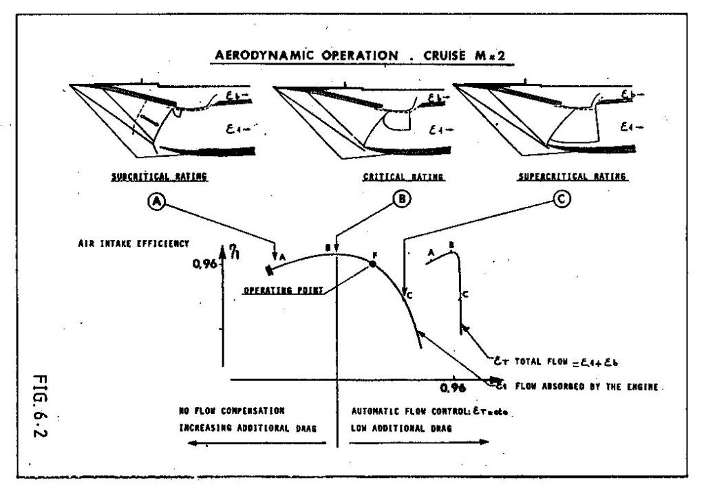
In normal operation (centre picture), the flow in the upper half of the intake was supersonic with a normal shock as required to decelerate to subsonic conditions. In the lower half the flow was decelerated to just sonic by the cowl shock. If the engine demand increased the region of supersonic flow got bigger until it nearly filled the intake (right hand picture).
The small reversed "D" zone just below the bleed slot is the supersonic region. The bleed flow entered the bleed aft of the normal shock.
Last edited by CliveL; 27th Oct 2012 at 08:44.
Join Date: Jan 2012
Location: Ontario
Age: 74
Posts: 82
Likes: 0
Received 0 Likes
on
0 Posts
Thanks for the pictures which I will try to absorb.
In the centre picture it looks like the cowl shock is the 3rd oblique shock mentioned in the paper.
As you have said, the region below the reversed "D" is subsonic and there appears to be no plane shock as I understand it, so I'm still a bit mystified.
Maybe I should give up on this very complex subject.
Join Date: Dec 2010
Location: Europe
Age: 88
Posts: 290
Likes: 0
Received 0 Likes
on
0 Posts
@ peter kent
As you say, a complex subject!
Maybe the missing link is that a plane shock is not the only way to decelerate through Mach 1.0. If the nose of a body is blunt, or if the angle you are trying to turn the flow through is too big then the shock wave becomes detached from the leading edge of the body. The bit of the shock on the 'cusp' is then actually a very strong plane (normal) shock and the flow immediately behind that part is subsonic. In the case of a sharp surface with a large tuning angle this subsonic flow allows air to escape from the high pressure side of the surface to the low pressure side. This would be the case for example if the flow onto the leading edge of an intake hit it at too big an angle.
Supersonic intakes come in two basic guises - external compression and internal compression. The ramjet intakes you have been reading about are the latter type in which all the deceleration/compression takes place inside the intake. In these designs the final compression is through a normal shock situated at the minimum area 'throat' of the intake where the flow is close to Mach 1.0. This flow is delicately balanced and if some engine disturbance causes the shock to move into the converging supersonic bit of the intake the whole shock system can be expelled giving all sorts of problems (inlet unstart). Generally they are used for high Mach numbers where their higher theoretical efficiency and low external/spillage drag count for more than the additional control system complexity and performance requirements.
In external compression intakes (a simple pitot intake would be an extreme example), all the compression is done by a system of shock waves that sit outside the intake. These intakes are less efficient than internal compression intakes and they also spill a lot of air which produces external drag. Usually restricted to low supersonic Mach numbers.
Concorde's intake was a "mixed compression" design which had some features of each type. At low engine mass flow demands the flow coming on to the cowl lip could be at too great an angle to maintain attached shock waves so it behaved a bit like that described earlier. You can see this most clearly in the left hand picture where the lower efficiency and higher spillage can be seen in the graph of efficiency against intake capture (epsilon). In this state the intake behaved more like an external compression type and there was no appreciable final normal shock.
At high engine demand the angle of flow hitting the cowl was such that the shock waves remained attached and the intake functioned more like an internal compression design. Again you can see this in the right hand picture which shows most of the intake throat covered by a normal shock and in the graph where total intake flow (engine plus bleed) is constant.
On condition there was a bit of each, but since it was designed to minimise spillage you cannot see the detachment of the cowl lip shock at the scale of the diagram.
Hope this is helpful rather than additionally confusing!
PS: Looking at the centre picture again, it occurs to me that the curved shock running from the lip back and up to the reversed "D" would actually be normal to the approaching local flow which was being turned by the ramps and the isentropic compression. This would be the shock you are looking for to decelerate the flow to subsonic conditions. In other words the intake was functioning as an external compression design over this part.
Last edited by CliveL; 28th Oct 2012 at 07:28.
Join Date: Jan 2012
Location: Ontario
Age: 74
Posts: 82
Likes: 0
Received 0 Likes
on
0 Posts
593 smoke reduction
ref question from Joliste
As I was working my way from 1 to 85 I read the above which reminded of a paper I filed 35 years ago:
"Development of Pollution Controls for Rolls-Royce RB211 and Olympus 593 Engines" by A B Wassall. I have picked out stuff relevant to the question:
The engines of the day generated smoke in the primary zone and partially consumed it in the rest of the combustor.
It was easier to reduce the production than increase the consumption but leaning the primary zone had an adverse effect on relight capability which then needed its own corrective action as was done on the 211. Metal temperatures went up with the leaning (as intimated by Joliste)
The 593 did not have the leaning option as it had to maintain an over-rich primary zone at TO to ensure an adequate weak extinction margin when throttled back at completion of supersonic cruise when the combustor had to operate at A/F ratios over 180.
In addition to the smoke problem the combustor weight and pressure loss had to be reduced.
These other two requirements led to the annular combustor and vaporizers which also reduced the smoke substantially. These three benefits were expected based on Pegasus experience.
why were the Olympus 593 s so smoky to start with, did they use excess fuel to help with cooling as some petrol engines do or was there some design feature which caused the smoke. It seeems to have been cured in later engines
rod
rod
"Development of Pollution Controls for Rolls-Royce RB211 and Olympus 593 Engines" by A B Wassall. I have picked out stuff relevant to the question:
The engines of the day generated smoke in the primary zone and partially consumed it in the rest of the combustor.
It was easier to reduce the production than increase the consumption but leaning the primary zone had an adverse effect on relight capability which then needed its own corrective action as was done on the 211. Metal temperatures went up with the leaning (as intimated by Joliste)
The 593 did not have the leaning option as it had to maintain an over-rich primary zone at TO to ensure an adequate weak extinction margin when throttled back at completion of supersonic cruise when the combustor had to operate at A/F ratios over 180.
In addition to the smoke problem the combustor weight and pressure loss had to be reduced.
These other two requirements led to the annular combustor and vaporizers which also reduced the smoke substantially. These three benefits were expected based on Pegasus experience.
Join Date: Jan 2008
Location: Edmonton, Alberta, Canada
Age: 56
Posts: 1
Likes: 0
Received 0 Likes
on
0 Posts
A couple of questions
Hi all, amazing thread! I hope I can add a couple of autopilot questions:
1. Did anyone ever use the IAS Hold button in the vertical mode, i.e. control speed with pitch instead of autothrottle? I always thought it might be used during climbout to maintain 250 knots under 10000 feet at full throttle.
2. How did the autopilot work in 'Go Around' mode and was it ever used, or were go arounds always done manually?
Thanks in advance,
Jim
Last edited by taichi40; 30th Nov 2012 at 14:37.
Join Date: Feb 2001
Location: UK
Posts: 223
Likes: 0
Received 0 Likes
on
0 Posts
The IAS hold in the pitch mode as used every flight as it was SOP for a decent.
Alt Hold engaged
Throttle back the engines to an intermediary point.
When speed came back to 350knts engage IAN hold to start the decent all the way at 350knts until a primed new altitude was reached, where the aircaft would level and the Autothrottles would come back into play
For sustained decent at M0.95, Mach hold would be used.
Join Date: Aug 2001
Location: Texas
Posts: 281
Likes: 0
Received 0 Likes
on
0 Posts
Question for British Airway Concorde Crew
I was doing some research for a little project, ran into a dead end.
I have seen the take off data card used by flight crews.
But, I can't seem to locate any images of the landing data card utilized.
So, wanted to ask. Did you have an official landing data card, similiar to the take off data card.
If so, do you perhaps have an image/scan of one? I've looked all over the internet, I can't locate anything.
If it was just written on a notepad then that explains everything.
I have an image of the Landing card used by Air France, just need to try and locate the one used by British Airways if there is/was a card/form. Any insight or help appreciated.
Best,
David
Join Date: Sep 2007
Location: UK
Age: 58
Posts: 128
Likes: 0
Received 0 Likes
on
0 Posts
From an occasional visitor:
I don't recall using landing data cards.... There may have been a version buried deep somewhere, but we generally just set the limits and did any necessary perf calculations.
Hope that helps.
I don't recall using landing data cards.... There may have been a version buried deep somewhere, but we generally just set the limits and did any necessary perf calculations.
Hope that helps.
Join Date: Feb 2013
Location: UK
Posts: 1
Likes: 0
Received 0 Likes
on
0 Posts
Beautiful
Ladies and Gentlemen,
I would just like to thank the contributors to this thread - it is by far and away the best piece I've ever visited on the internet. Bar none. It has taken me months (and many arguments with a jealous girlfriend!) to get this far - I didn't want to ask any questions which had already been answered.
My experience; never flew on her but when I heard she was being decommissioned, I decided to make every effort to watch a Concorde take off and hang about for the final three consecutive landings at LHR. I have never seen so many grown men cry. I would have counted more but I think I got something in my eye..
As a Chartered Engineer working on a multi-disciplinary rail project, I am amazed that a project as complex as this was managed across the Channel in the 1960's; how was the Systems Engineering managed - who drove the requirements for the Jet, potential carriers, engineers or politicians?
CliveL - your input to this has been amazing - a quick question if I may; you say wind modelling played a big part in the development of the aerodynamics, how big did the models go? Did you have the luxury of testing a full-scale model? or maybe full-scale parts or sub assemblies?
Dude - its my understanding that you worked on the Maintenance Engineering of the jet, many thanks for your thoughtful remarks. Please keep those grey cells going! Was any maintenance every brought forward when it became clear a member of the Royal Family was to fly? How much input did the carriers have in generating the maintenance periodicities for the works? Did these change mid-life? If so, what and why?
ChristiaanJ - I am blown away by just how much cutting-edge (for the time!) kit was provided to get her up. In the railway, we try and steer clear from 'New and Novel' because of the increased assurance risk required. Did the onboard systems required extended testing to assure the authorities? Please forgive my memory, but I seem to recall seeing the test craft have many 'computers' in the passenger areas while testing - what did these record? How did the data support development?
Bellerophon - your post on 18th Dec 2010, 15:20 #875 had me in tears for about 20 minutes - wife to be thought I'd found out someone had died. hhmmmm..
As someone who's hoping to secure their PPL in March / April I found your piece extraordinary - can you confirm rough altitude above aerodrome (AKA QFE for us GA boys?) before instigating the 25� left bank to commence the turn out over Jamaica bay?
A thoroughly enjoyable and often moving read. Thank you all. Like a good book / film I think I'll come to read it from page one before long - who'd have thought missing out the APU would cause such a stir?!
Join Date: Apr 2007
Location: EU
Posts: 28
Likes: 0
Received 0 Likes
on
0 Posts
Thanks from me too for this great thread!
Does anyone remember a Concorde passing a manned balloon? I have seen footage of it and it did not look planned. You can find more details in an old thread:
some years ago: Concorde passes balloon crossing atlantic ocean [Archive] - PPRuNe Forums
Does anyone remember a Concorde passing a manned balloon? I have seen footage of it and it did not look planned. You can find more details in an old thread:
some years ago: Concorde passes balloon crossing atlantic ocean [Archive] - PPRuNe Forums
Join Date: Dec 2010
Location: Europe
Age: 88
Posts: 290
Likes: 0
Received 0 Likes
on
0 Posts
As a Chartered Engineer working on a multi-disciplinary rail project, I am amazed that a project as complex as this was managed across the Channel in the 1960's; how was the Systems Engineering managed - who drove the requirements for the Jet, potential carriers, engineers or politicians?

Once it was decided to go, I would say that the system requirements were largely driven by the difficulty of the task - more a question of finding out how to make it work than of optimising. The overall aircraft requirements were driven by the engineers, but criticised by the potential customer airlines in regular meetings.
Safety requirements were specified in a completely new airworthiness code - a sort of comprehensive set of special conditions, which were generally more severe than the subsonic codes of the time. Concorde, for example, was, AFAIK, the first civil aircraft to be certificated against the requirements that now exist as 25.1309.
But nobody really knew what to write for supersonic flight and, in particular, the transition from subsonic, so to some extent one made it up as one went along, using prudent common sense and engineering judgement. Fuel system transfer rates for example had to match a requirement that it should be possible to abandon the acceleration at any point and return safely to subsonic conditions - and the deceleration was much quicker than the acceleration!
wind modelling played a big part in the development of the aerodynamics, how big did the models go? Did you have the luxury of testing a full-scale model? or maybe full-scale parts or sub assemblies?
Supersonic testing mainly at 1/30 scale; low speed 1/18. The biggest model was a 1/6 scale half model used mainly for icing tests. Isolated intake tests, IIRC, about 1/10 scale, but we did have a full scale intake operating in front of an Olympus 593 at Mach 2.0 in Cell 4 at NGTE Pyestock.