


Concorde question


Join Date: Dec 2010
Location: Europe
Age: 88
Posts: 290
Likes: 0
Received 0 Likes
on
0 Posts
Brian,
I don't think there is any published explanation, but maybe this will help.
Basically the problem with #4 intake was that it was on the RHS of the airplane. We are talking about low speed right? and especially zero forward speed when the engine is trying to suck as much air as it can get from wherever it can get it. That means that the induced angle of attack on all the intake leading edges is going to be high.
The best drawing I can find that shows the flow into the right hand pair is this
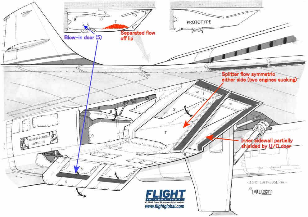
The intake leading edges were all sharp, so the flow would separate if subjected to a high AoA. The upper lip was protected a little by the wing leading edge, and we were obliged to modify the prototype LE ahead of the intakes to prevent underwing vortices developing at low AoA in cruise which also helped a bit.
The lower lip had a substantial separated flow 'bubble' at low forward speed as shown in red, but this cleared up quite quickly as the aircraft gathered speed. It was'cured' by the blow-in doors.
The inner sidewalls were shielded by the landing gear doors, so the AoAs on the sidewall on that side were quite modest.
The splitter was of course subject to equal flow demands on either side so the flow over that was pretty well symmetric.
That leaves the two outer sidewalls which, look for all the world like highly swept delta wings with sharp LEs mounted vertically.
Like all such wings when operated at high AoA they develop powerful vortices on the 'leeward' side. Looking back towards the engine the vortex on #4 engine was anticlockwise and that on #1 was clockwise. [Hope I got that one the right way round ]
]
The OL593 rotates clockwise looking aft so the induced incremental AoA on the compressor blades was different on #1 and #4. The difference was enough to trigger some mild blade vibration - hence the rpm restriction until the intake capture was good enough to reduce the vortex strength.
I don't think there is any published explanation, but maybe this will help.
Basically the problem with #4 intake was that it was on the RHS of the airplane. We are talking about low speed right? and especially zero forward speed when the engine is trying to suck as much air as it can get from wherever it can get it. That means that the induced angle of attack on all the intake leading edges is going to be high.
The best drawing I can find that shows the flow into the right hand pair is this
The intake leading edges were all sharp, so the flow would separate if subjected to a high AoA. The upper lip was protected a little by the wing leading edge, and we were obliged to modify the prototype LE ahead of the intakes to prevent underwing vortices developing at low AoA in cruise which also helped a bit.
The lower lip had a substantial separated flow 'bubble' at low forward speed as shown in red, but this cleared up quite quickly as the aircraft gathered speed. It was'cured' by the blow-in doors.
The inner sidewalls were shielded by the landing gear doors, so the AoAs on the sidewall on that side were quite modest.
The splitter was of course subject to equal flow demands on either side so the flow over that was pretty well symmetric.
That leaves the two outer sidewalls which, look for all the world like highly swept delta wings with sharp LEs mounted vertically.
Like all such wings when operated at high AoA they develop powerful vortices on the 'leeward' side. Looking back towards the engine the vortex on #4 engine was anticlockwise and that on #1 was clockwise. [Hope I got that one the right way round
]The OL593 rotates clockwise looking aft so the induced incremental AoA on the compressor blades was different on #1 and #4. The difference was enough to trigger some mild blade vibration - hence the rpm restriction until the intake capture was good enough to reduce the vortex strength.
Thread Starter
Just finished the Haynes 'Concorde workshop manual'
This is a collaboration between a retired Concorde Captain and Flight Engineer.
The one excerpt that really caught my eye was the reference to the method of construction and differences between the British and French built Aircraft.
'The French fuselage was designed to safe life principles while the British was designed to fail safe. From window line to window line across the top of the fuselage Bristol used three skin panels overlapping at 10 o'clock and 2 o'clock while Toulouse used two, overlapping at 12 o'clock'
This revelation was a big surprise to me, for a production run of 14 airframes two different construction methods were employed apparently, amazing.
I had always thought the airframes were virtually identical.
Anyone have any further insight on this ?
Last edited by stilton; 27th Aug 2012 at 06:30.
Join Date: Feb 2006
Location: UK
Posts: 592
Likes: 0
Received 0 Likes
on
0 Posts
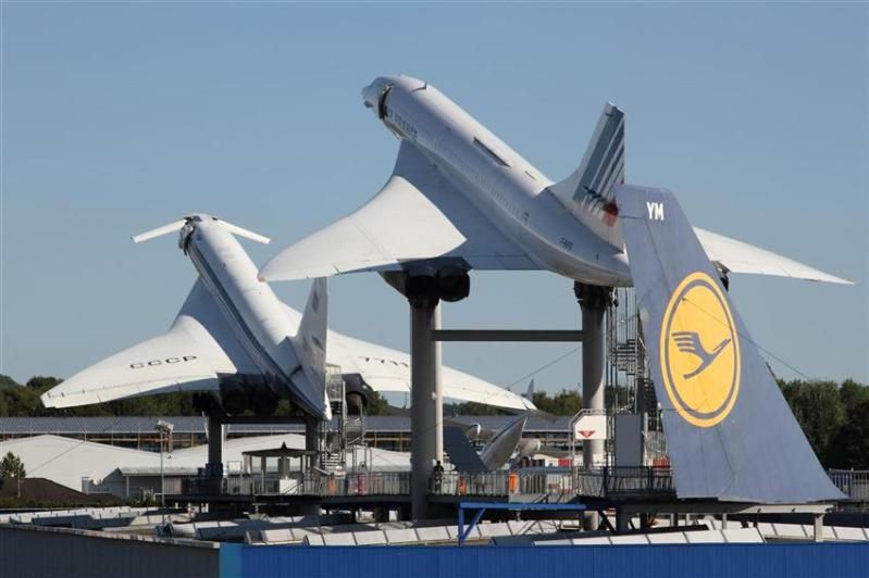
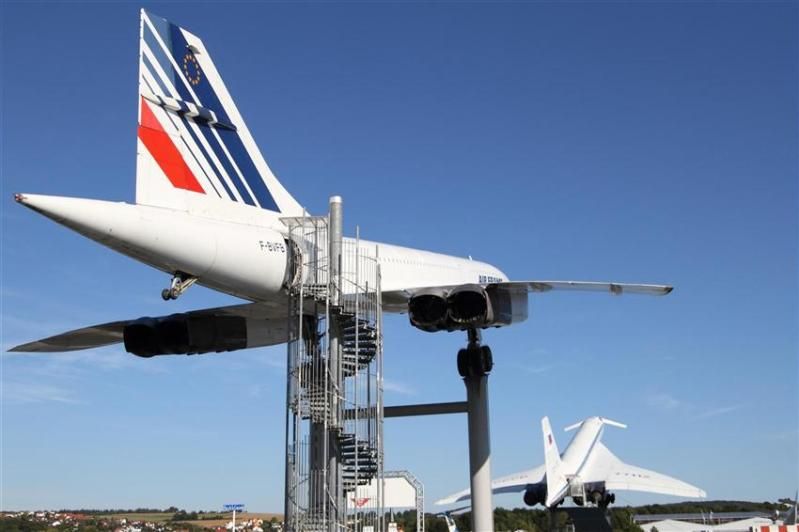
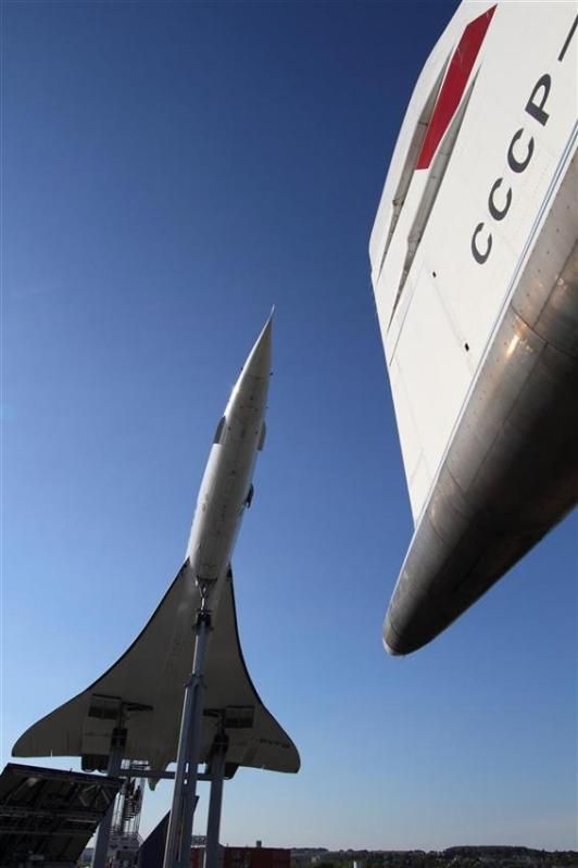
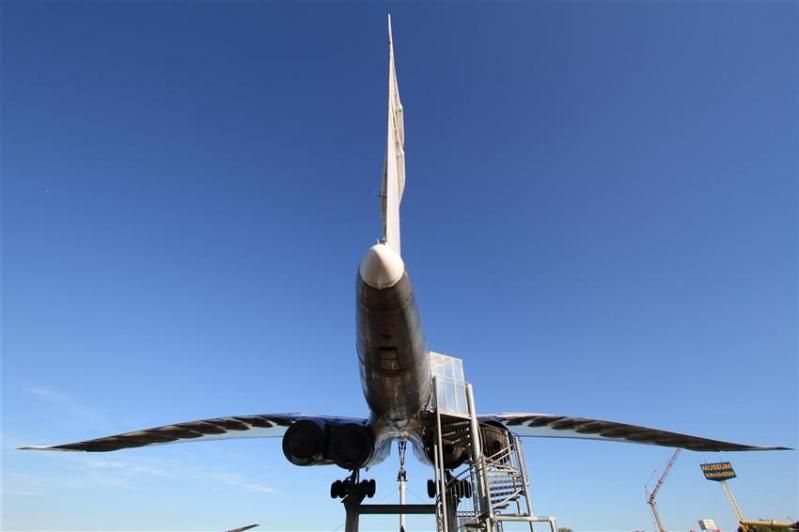
Concorde and TU-144 at Sinsheim
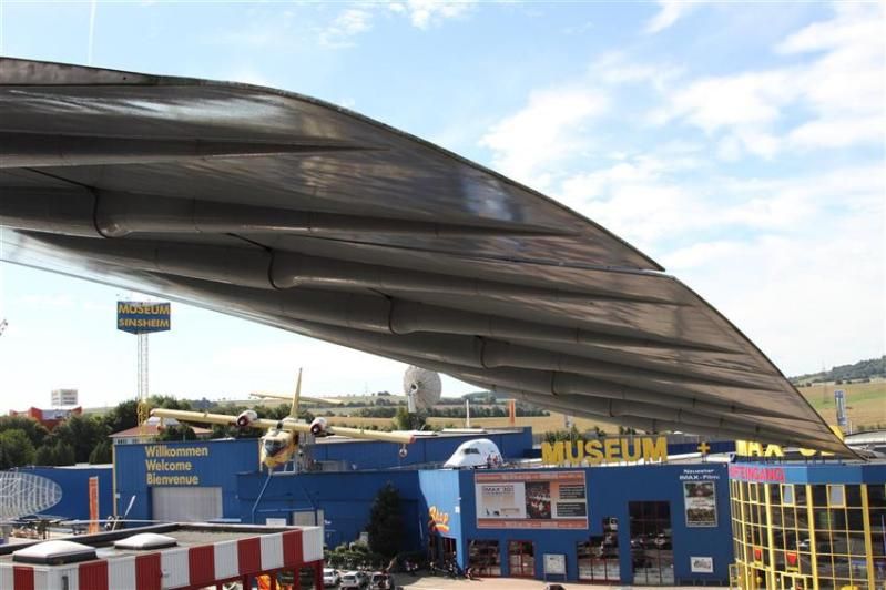
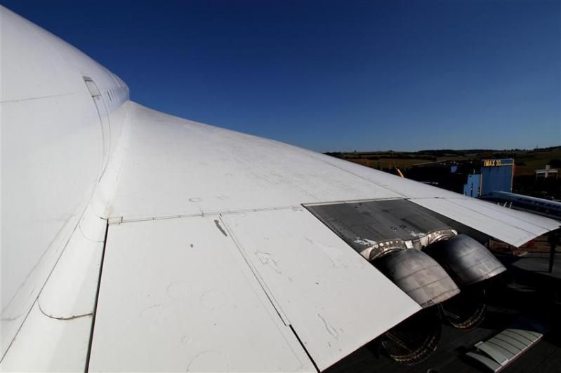
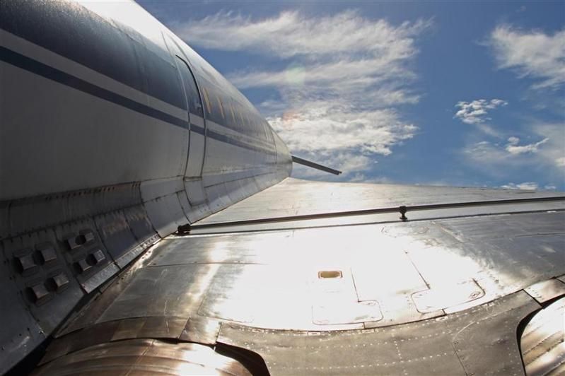
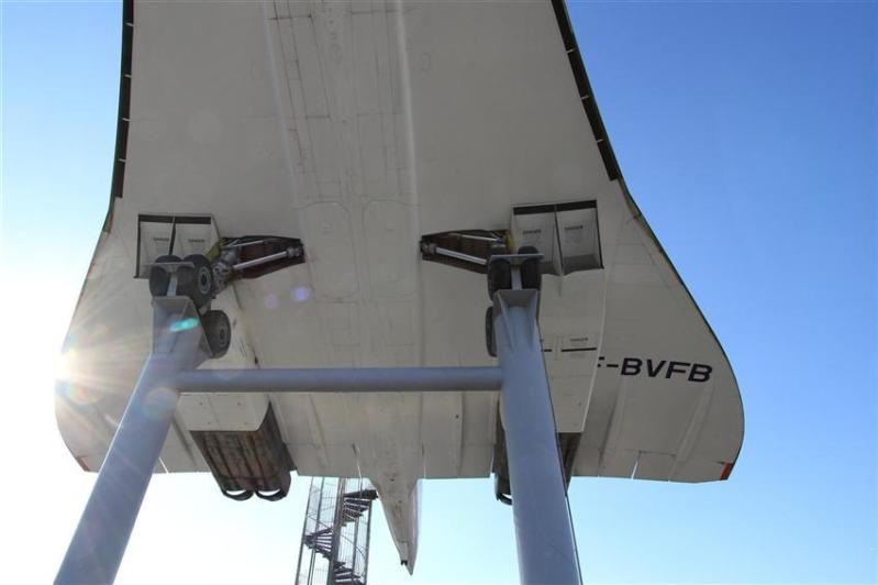
Earlier this week I had the great pleasure of a late afternoon followed by a full day at the Sinsheim technical museum near Heidelberg. Highly recommended and much more than just a museum; just ask my children what they thought of the helter-skelter from elevated Ilyushin IL-18 back down to the ground, or the twisting and turning stainless steel tubular slide from museum roof mounted DC3, through a hole in the roof, and back to the ground level entrance! The staff I encountered were all friendly and informed and I now look forwards to a day at the sister museum in Speyer - replete with 747-200 on the roof on which visitors can walk the wing.
Anyway, of relevance to this thread I thought I'd shared some of my photos of Concorde F-BVFB and Tupolev TU-144 77112. It was tremendous to be able to walk backwards and forwards between the two, directly comparing design features and relative elegance of execution. Both are achievements for mankind but I have to say that to me not being an aeronautical engineer, Concorde won every time - dreary Air France cabin notwithstanding - with the larger Tupolev coming over as somewhat clumsy; let alone knowing engine technologies to be a world apart, just compare the wheel bogies as one example, and then the cleanliness of wing design as another. Yes, the Tupolev canards were a novel feature, but I understand they were only necessary in the first place because of lower speed control issues as a result of more basic aerodynamics.
Like any aircraft on static display exposed to the elements both airframes could do with some TLC, but here are the photos:
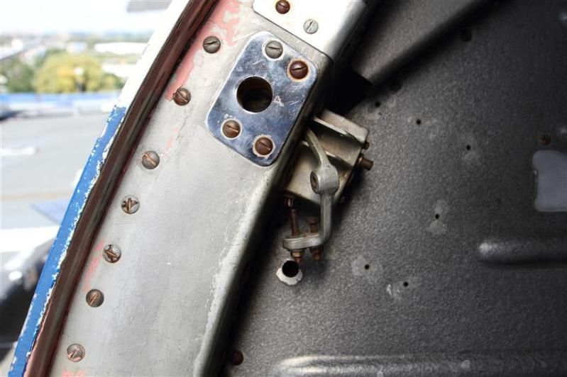
Concorde aft cabin door
TU-144 aft cabin door
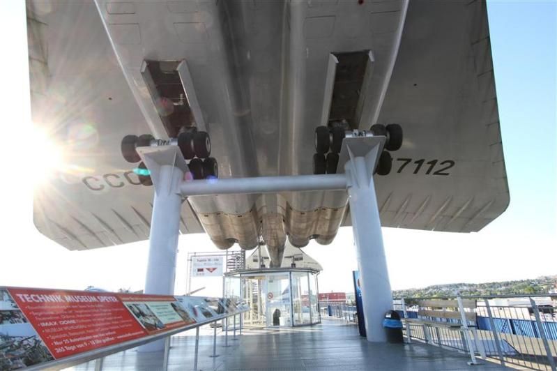
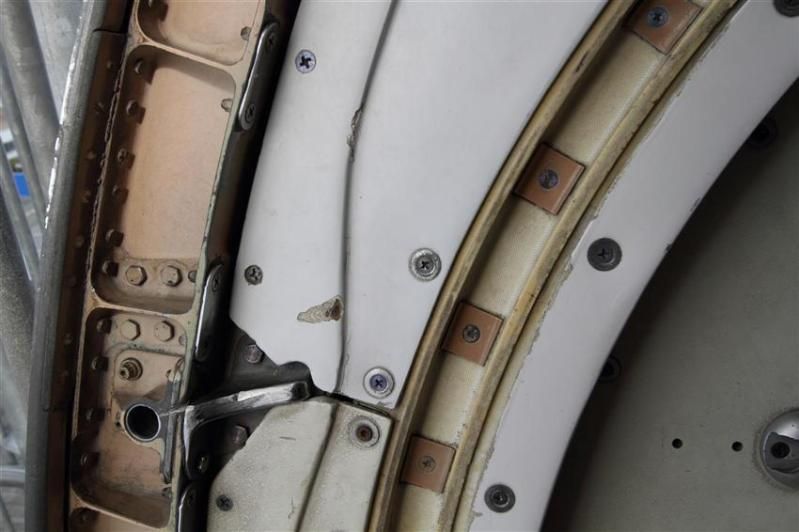
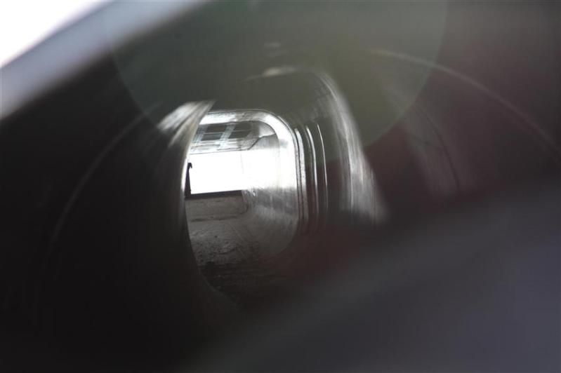
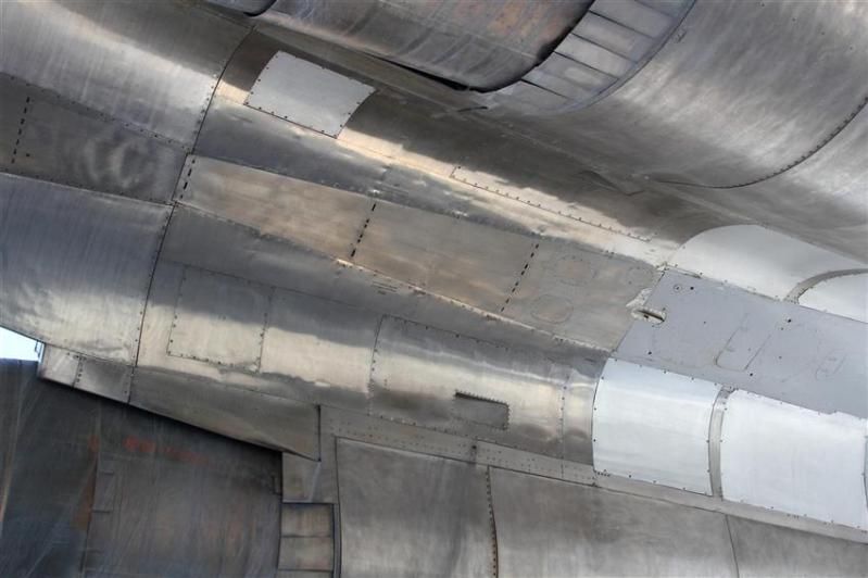
TU-144 No 4 engine location viewed from exhaust towards inlet (and directly in to the sun!)
To be continued in separate post as I have hit the photo count ceiling in this one.
Anyway, of relevance to this thread I thought I'd shared some of my photos of Concorde F-BVFB and Tupolev TU-144 77112. It was tremendous to be able to walk backwards and forwards between the two, directly comparing design features and relative elegance of execution. Both are achievements for mankind but I have to say that to me not being an aeronautical engineer, Concorde won every time - dreary Air France cabin notwithstanding - with the larger Tupolev coming over as somewhat clumsy; let alone knowing engine technologies to be a world apart, just compare the wheel bogies as one example, and then the cleanliness of wing design as another. Yes, the Tupolev canards were a novel feature, but I understand they were only necessary in the first place because of lower speed control issues as a result of more basic aerodynamics.
Like any aircraft on static display exposed to the elements both airframes could do with some TLC, but here are the photos:
Concorde aft cabin door
TU-144 aft cabin door
TU-144 No 4 engine location viewed from exhaust towards inlet (and directly in to the sun!)
To be continued in separate post as I have hit the photo count ceiling in this one.
Join Date: Feb 2006
Location: UK
Posts: 592
Likes: 0
Received 0 Likes
on
0 Posts
...and the second post to conclude the photos and ask a question:
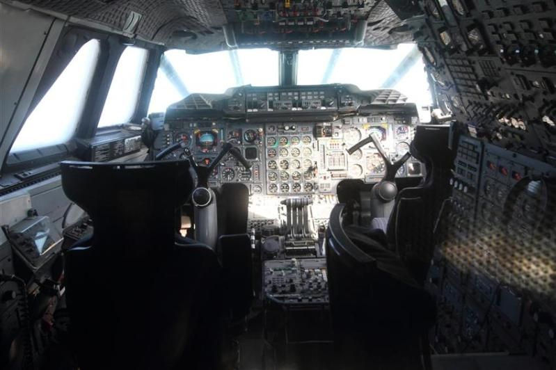
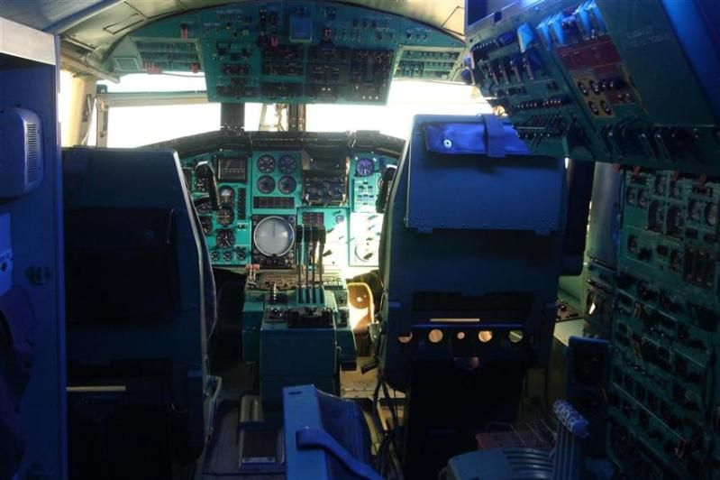
Concorde cockpit (through hazy perspex screen)
TU-144 cockpit (also through hazy perspex screen)
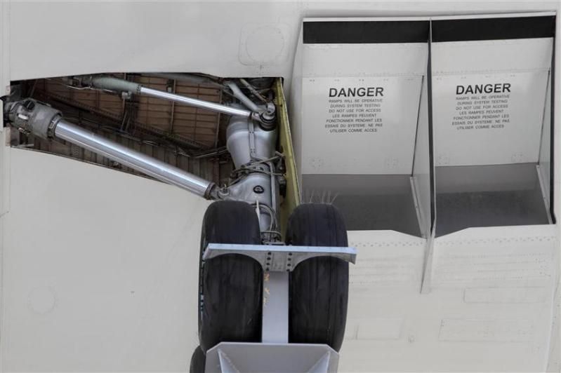
A sign that made me chuckle

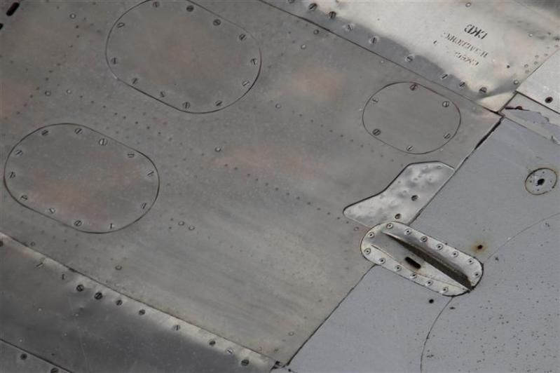
I hope that these pictures were of interest and can spark some further discussion in this amazing thread. If I can have the temerity to start the ball rolling with a TU-144 question, I was intrigued to notice the following tiny vane situated on the fuselage base between engines 2 and 3. Closer inspection revealed an adjacent hole, perhaps indicating pressure measurement? Anyway, ideas or proven fact welcome!
As observed
Cropped
Concorde cockpit (through hazy perspex screen)
TU-144 cockpit (also through hazy perspex screen)
A sign that made me chuckle
I hope that these pictures were of interest and can spark some further discussion in this amazing thread. If I can have the temerity to start the ball rolling with a TU-144 question, I was intrigued to notice the following tiny vane situated on the fuselage base between engines 2 and 3. Closer inspection revealed an adjacent hole, perhaps indicating pressure measurement? Anyway, ideas or proven fact welcome!
As observed
Cropped
Last edited by The late XV105; 31st Aug 2012 at 23:44. Reason: Additional photos
I think the TU144 needs an entirely new thread. Oooh questions questions....
Join Date: Sep 2000
Location: UK
Posts: 613
Likes: 0
Received 0 Likes
on
0 Posts
Best book ever:-

PS - Other web based retailers are available....
PS - Other web based retailers are available....
Join Date: Dec 2010
Location: Europe
Age: 88
Posts: 290
Likes: 0
Received 0 Likes
on
0 Posts
@ Stilton
They were. Just that all the UK manufactured subassemblies had three skin panels and the French bits two. Made no difference when they were mated up - the stringers matched and the skins were simply riveted to the frames.
@ The Late XV105
Pure speculation - a drain hole with some sort of guide to deflect the fluid away from some other part?
I had always thought the airframes were virtually identical.
@ The Late XV105
Pure speculation - a drain hole with some sort of guide to deflect the fluid away from some other part?
Do a Hover - it avoids G
Join Date: Oct 1999
Location: Chichester West Sussex UK
Age: 91
Posts: 2,206
Likes: 0
Received 0 Likes
on
0 Posts
The late XV105
Dunno about the source of your info on this but it may have got a bit garbled in the telling.
With a plain slender delta on the approach the trailing edge control surfaces will be slightly up and as speed is reduced this angle will increase slightly. If you want to raise the nose in the flare then even more stick back will be needed. This gives - if you like - a wing with a negative flap angle and so rather less lift needing a higher speed than you miught wish.
If you add some canards to give a big nose up force then to trim the aircraft the trailing edge surfaces will all be down a bit - giving a flapped delta with considerable benefit in terms of reduced approach speed.
The Tu144 with canards was able to land on the display runway at Le Bourget and take the second turn off right to the aircraft park - a quite remarkable demonstration of its modest speed on finals.
Yes, the Tupolev canards were a novel feature, but I understand they were only necessary in the first place because of lower speed control issues as a result of more basic aerodynamics.
With a plain slender delta on the approach the trailing edge control surfaces will be slightly up and as speed is reduced this angle will increase slightly. If you want to raise the nose in the flare then even more stick back will be needed. This gives - if you like - a wing with a negative flap angle and so rather less lift needing a higher speed than you miught wish.
If you add some canards to give a big nose up force then to trim the aircraft the trailing edge surfaces will all be down a bit - giving a flapped delta with considerable benefit in terms of reduced approach speed.
The Tu144 with canards was able to land on the display runway at Le Bourget and take the second turn off right to the aircraft park - a quite remarkable demonstration of its modest speed on finals.
Join Date: Dec 2010
Location: Europe
Age: 88
Posts: 290
Likes: 0
Received 0 Likes
on
0 Posts
I entirely agree with John Farley's comments. We were planning to fit canards on the second generation SST for exactly those reasons - they also gave a slightly better L/D in take-off climb which was useful for noise abatement, but they only just earned their keep in terms of economics!
Thread Starter
Clive,
While not disputing what you are saying about the construction why was the French method described as 'safe life' and the British 'fail safe ? '
It sounds significantly different.
While not disputing what you are saying about the construction why was the French method described as 'safe life' and the British 'fail safe ? '
It sounds significantly different.
Join Date: Dec 2010
Location: Europe
Age: 88
Posts: 290
Likes: 0
Received 0 Likes
on
0 Posts
@stilton
I can't give you much detail I'm afraid - as JT said a few posts ago:
Basically the differences lie in the fine details of the structure. To quote from a Googled article:
whereas:
On the UK parts there were detailed features such as crack-stoppers and multiple load paths whereas the French design relied on analysis and testing to establish where and when any failures might be expected to occur. The consequence was that the ultimate life of the airframe was dictated by the number of thermal fatigue cycles accumulated in the Farnborough major fatigue facility divided by the factor of safety demanded by the airworthiness authorities which was conservative because one was really into unknown territory.
I can't give you much detail I'm afraid - as JT said a few posts ago:
No point asking Clive .. he's an aerodynamicist and, hence, only talks in slugs/cubic foot.
Safe-life refers to the philosophy that the component or system is designed to not fail within a certain, defined period. It is assumed that testing and analysis can provide an adequate estimate for the expected lifetime of the component or system. At the end of this expected life, the part is removed from service.
Fail-safe designs are designs that incorporate various techniques to mitigate losses due to system or component failures. The design assumption is that failure will eventually occur but when it does the device, system or process will fail in a safe manner.
Thread Starter
I realize it's all academic now Clive but the two philosophies do sound significantly different.
Just for the sake of argument if the two fleets were still operating surely BA's would be approved for a longer life with the fail safe method of construction ?
Just for the sake of argument if the two fleets were still operating surely BA's would be approved for a longer life with the fail safe method of construction ?
Join Date: Feb 2009
Location: Jungles of SW London
Age: 77
Posts: 354
Likes: 0
Received 0 Likes
on
0 Posts
The Late XV105
I am not in any position to offer an answer to your question XV105, but may I offer a 'speculation'? I would hazard that the projection you highlight might be a Radio Altimeter aperture? It looks like a casting or even a forging and far too fancy for a drain. It seems to me the surface in which the aperture is 'machined', would be pretty much horizontal in the landing configuration and thus offer accurate height of the centre of gravity perhaps? Given that the cockpit would be many feet above that, it makes sense.
Errr..... I'll get me coat.
Errr..... I'll get me coat.
Join Date: Dec 2010
Location: Europe
Age: 88
Posts: 290
Likes: 0
Received 0 Likes
on
0 Posts
.. I really shouldn't be as cheeky as I tend to be at times ...
Last edited by CliveL; 2nd Sep 2012 at 10:58.
Join Date: Dec 2010
Location: Europe
Age: 88
Posts: 290
Likes: 0
Received 0 Likes
on
0 Posts
Just for the sake of argument if the two fleets were still operating surely BA's would be approved for a longer life with the fail safe method of construction ?
Join Date: Dec 2010
Location: Europe
Age: 88
Posts: 290
Likes: 0
Received 0 Likes
on
0 Posts
Don't know much about radio altimeters. First thoughts were that it was some sort of vortex generator, but seems a funny place to have one. Second thoughts were that the 'vane' standing off the surface was there to generate some sort of suction (the 'hole' seems to be on the leeward side) to make sure that the inside did drain in all conditions.