


QANTAS A380 Uncontained failure.

Join Date: Feb 2005
Location: flyover country USA
Age: 82
Posts: 4,579
Likes: 0
Received 0 Likes
on
0 Posts
I do not know what methods (torque, wrench arc, ...) are authorized in ATA100 pubs for Trent maintenance. And I won't speculate on whether a torque wrench was available/calibrated/properly used. Your question still stands.


Join Date: Sep 2007
Location: Australia
Age: 64
Posts: 55
Likes: 0
Received 0 Likes
on
0 Posts
Some news on the repair plans for the aircarft.
No return to home base.
Qantas A380 engine failure | Repairs set to begin | $150 million bill
No return to home base.
Qantas A380 engine failure | Repairs set to begin | $150 million bill
Join Date: Dec 2010
Location: S 51 N
Age: 84
Posts: 196
Likes: 0
Received 0 Likes
on
0 Posts
4-corners
I am more than only dissatified that this link was taken of this thread.
Four Corners - QF32
It is the first foto sequence that shows more than the ATSB fotos do. E.G. it shows where the stub oil pipe was mounted and it shows in that blow up of the recovered IP disk segment that there is decouloration of the bore section - blueish signature -
This leads to two conclusions:
a. there was indeed an oil fire that weakened the disk and
b. the stub pipe broke probably by fatique
What immediately raises the question what caused that fatique failure ??
If I am not completely off track fatique failure is caused by intermittend loads. We also know by those graphs published in the ATSB report that oil pressure was decreasing from normal levels but stayed well above critical amounts, as was the quantity of oil available.
This once again very clearly indicates the total failure of that oil tube happened at the time the engine disintegrated and only the oil spelled through the fissure had accumulated enough of an amount to start that fire.
It is by no means identified in that report what really is the cause of the selfdestruction of the engine and subsequently almost the loss of QF 32. But typically it mentioned that 19 engines had received a "new module" and just that one that blew apart didn�t.
But I think by now every one that has had a closer look to the sequence of events has to come to the conclusion that vibrations of an unexpected amount has killed that engine. Though outside leakage that also is testimony of the last incident of a QF airbius flying to London on 3 engines.
I believe it is time to release those unknowns of the engine behaviour. It may hurt RR but it will give a safer operation of that engine / aircraft combination a chance.
I hope that RR is far beyond our imagination of whatneeds to be done.
Jo
Join Date: Dec 2003
Location: On the ground for now.
Posts: 274
Likes: 0
Received 0 Likes
on
0 Posts
Rolls Royce under scrutiny.
Mar 28, 2011
"A Four Corners investigation into last year's mid-air explosion of a Qantas A380 jet engine raises serious concerns about quality controls at Rolls-Royce.
It reveals the engine-maker was aware of a faulty weld on an oil pipe in one its Trent 900 engines a year before the explosion happened.
Despite the initial warning, the company went on to manufacture another faulty pipe.
The 2009 crack was caused by a sub-surface void which had been created in the welding process.
Three more oil pipes were found that were considered by regulators to fall outside the safety margin for thickness."
Rolls-Royce under scrutiny after Qantas explosion - ABC News (Australian Broadcasting Corporation)
Join Date: Jan 2008
Location: USA
Posts: 100
Likes: 0
Received 0 Likes
on
0 Posts
Join Date: Dec 2010
Location: S 51 N
Age: 84
Posts: 196
Likes: 0
Received 0 Likes
on
0 Posts
News on QF / Trent 900
I just found this report in "flightglobal"
Partial power loss on Qantas A380 caused by oil leak
I think of greatest importance is this sentence of the report
Quote:
The ATSB add that it is now conducting a "holistic investigation" into the oil leak and other reported cases of oil leaks in Trent 900 engines.
As I understand this announcement, ATSB has come to the conclusion that there has to be more behind these engine problems - QF 32 and others - than just oil feed pipes.
Jo
Nothing New here
All Engine models leak oil sometimes. Where it leaks is important. Internally is important as it can ignite.
The problems with this engine are under close watch to ensure that corrective action is effective.
All Engine models leak oil sometimes. Where it leaks is important. Internally is important as it can ignite.
The problems with this engine are under close watch to ensure that corrective action is effective.
Join Date: Apr 2008
Location: Sydney
Posts: 3
Likes: 0
Received 0 Likes
on
0 Posts
"The Australian" newspaper writes today:
"Rolls-Royce was unable to tell how many more of its Airbus A380 engines might explode after last year's Qantas near-disaster near Singapore because of a lack of records."
see link:
Records missing on A380 engines | The Australian
"Rolls-Royce was unable to tell how many more of its Airbus A380 engines might explode after last year's Qantas near-disaster near Singapore because of a lack of records."
see link:
Records missing on A380 engines | The Australian
Guest
Posts: n/a
vic cairns
From the article, I see the minimum value for wall thickness of this stub pipe is .5mm. Can that be correct?? It is also the minimum "crest" measurement for the splines at IP shaft rigid coupling. The AD specifies a range for splines of 0.5mm to 2.65mm, so we know the AD is correct, but 0.5mm for an oil feed pipe? I think that is about 0.045 inch?
From the article, I see the minimum value for wall thickness of this stub pipe is .5mm. Can that be correct?? It is also the minimum "crest" measurement for the splines at IP shaft rigid coupling. The AD specifies a range for splines of 0.5mm to 2.65mm, so we know the AD is correct, but 0.5mm for an oil feed pipe? I think that is about 0.045 inch?
change in fatigue location
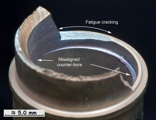
The interim report text calls out a (to me very minor) change in the diagnosed fatigue crack location of interest. This version is posted in the new interim report:
while this is the one provided late last year--downsampled by me to be a better match to the new and to be more suitable for posting here:
Here is a link to the full resolution version from last year:
full resolution 2010 picture
(depending on your browser and Photobucket, the high resolution one will display at less than full resolution when you click my link--the clue may be a plus sign in your mouse pointer--one more click will take you up to full res.
I'm not claiming this to be important--but it is new.

Guest
Posts: n/a
archae86
It is extremely important. The smooth face is not indicative of either wear or fatigue, imo. For all we know that could be a keyway to accept a "c" ring, coupling m/f lines. It's tempting, but the "pipe" was done to exhaustion, so suffice that I still believe the "misalignment" is wear from excess vibration twixt male and female, not a blown end bore assignment. To add (edit), the length of the arrow indicating fatigue could be the limit of the metal as built. In other words, the smooth area defines the "former" position of the missing metal. That is oddball, and if I didn't know better, I would say that interpretation is misleading.......not to mention that the gouge at the end of the pipe mimics the limit of vibration. Note the "swirl" marks on the face of the injury? One might almost calculate the frequency of the damaging vibration from those telltales....
chuchu
Smokin' Eddie, that ain't too pretty much thick enough for oil, innit ?
bear
Join Date: Dec 2010
Location: Middle America
Age: 84
Posts: 1,167
Likes: 0
Received 0 Likes
on
0 Posts
Bear,
The "new" area they now point out as the fatigue crack almost looks to me as a brittle failure (no ductility) rather than a fatigue failure, in other words, it just snapped due to lack of support of the rest of the structure that was progressively failing. I would have a tendency to agree with you relative to vibration.
TD
Guest
Posts: n/a
Hi TD...
This picture has always shown to me a coupling I have known as a "Quik-Couple". Male/Female, a sliding sleeve to align and retain the two mates. The "Misaligned counter bore" I have assumed is NOT a machining fault, but the result of a loose connection where the male, the counter-bored part is vibrating in the walls of the recipient.
A "counter bore" is the attaching piece, "counter" meaning mate. Its "misalignment" responsible for the sloughing off of wall material.
The striae on the walls show a vibration that likely blew off the large pieces, and in so doing, opened up the "cone" of play that caused the brittle fracture you speak of ?
Join Date: Jan 2008
Location: uk
Posts: 857
Likes: 0
Received 0 Likes
on
0 Posts
Would be nice to have pictures of the whole pipe assembly - I still feel we're only looking at half (or less) of the picture.

Join Date: May 2011
Location: Aussie
Age: 77
Posts: 1
Likes: 0
Received 0 Likes
on
0 Posts
ATSB May 18 Update
Is there new information contained in this ATSB Interim Factual Update on 18 th May? Interested in expert comments.
Thanks
The Australian Transport Safety Bureau is investigating an occurrence involving a Qantas A380 aircraft that experienced an uncontained engine failure over Batam Island, Indonesia on 4 November 2010. The aircraft landed safely in Singapore having returned with the aircraft's No 2 engine shut down. There were no injuries.
The investigation team has inspected the damaged engine and components and determined the sequence of events that led to the failure of the engine disc.
The investigation is also examining the airframe and systems damage that resulted from the engine disc burst to understand its effect on those systems and the impact on flight safety. That includes their effect on the aircraft�s handling and performance and on crew workload. A flight simulator program was used to conduct a number of tests in a certified A380 flight simulator. Analysis of the flight simulation test data is ongoing.
The investigation is continuing.
The investigation team has developed into a large multi-agency group consisting of the Australian Transport Safety Bureau (ATSB) as the lead investigation agency with assistance from the French Bureau d�Enqu�tes et d�Analyses (BEA), the Air Accident Investigation Branch of United Kingdom (UK AAIB), the Air Accident Investigation Bureau of Singapore (AAIB Singapore), the National Transport Safety Committee of Indonesia (NTSC), and advisors to the various investigation bodies from Rolls-Royce, Airbus, SAFRAN Sagem, Honeywell (USA and UK), Aerolec UK and Singapore Aero Engine Services Private Limited.
Since the on-site phase of the investigation, the European Aviation Safety Agency (EASA) has facilitated a meeting between EASA, Rolls-Royce, Airbus and the Civil Aviation Safety Authority of Australia (CASA) with the ATSB, BEA and UK AAIB attending as observers. That meeting was to establish if the Rolls-Royce Trent 900 engine and the Airbus A380 airframe met the design certification requirements for the engine and airframe in light of the significant damage that resulted from this event. The engine manufacturer - Rolls-Royce - and the airframe manufacturer - Airbus - presented technical data and findings to that group. EASA and CASA agreed that, based on the information supplied, the airframe and engine meet the certification requirements. However, further investigation into the aircraft�s structure and systems and engine behaviour is continuing to fully understand this event and establish if there are safety issues that need to be addressed.
The ATSB, UK AAIB and Rolls-Royce have inspected the damaged engine and components
and determined the sequence of events that led to the failure of the engine disc. As a result of those findings, Rolls-Royce published a series of non-modification service bulletins (NMSB) with various amendments and a Service Bulletin (SB) to manage the continued serviceability of the Rolls Royce Trent 900 engine and EASA issued two Emergency Airworthiness Directives and one Airworthiness Directive. Qantas Airways initially placed operational restrictions on the Australian A380 fleet in conjunction with CASA. Commencing on 16 January 2011, those restrictions were progressively removed, as the fleet�s continued airworthiness was established.
The investigation has found that the intermediate pressure (IP) turbine disc failed as a result of an overspeed condition, liberating sections of the IP turbine disc that then penetrated the engine case and wing structure. The disc failure was initiated by a manufacturing defect in an oil feed pipe that resulted in a wall thickness reduction in an area that is machined to receive a coarse filter. That section of the oil feed pipe sustained a fatigue crack during engine operations that led to an internal engine oil fire that weakened the IP turbine disc. In turn, a circumferential fracture was induced around the disc, allowing it to separate from the IP turbine shaft. The unrestrained disc accelerated to critical burst speed. This led to the No 2 engine failure and subsequent significant penetration damage to the airframe structure and systems.
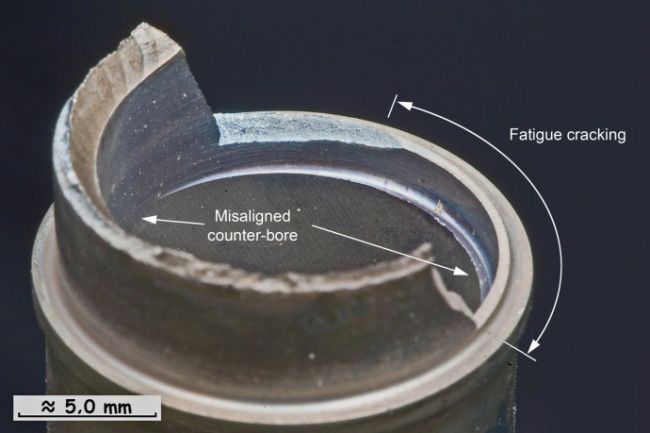
Since the ATSB�s Preliminary Report was issued, analysis of the oil feed pipe fracture surface has progressed and the investigation team has a better understanding of the failure mechanism. Technical reviews to date of the available evidence have established that the location of the fatigue cracking that was depicted in Figure 9 of the Preliminary Report1 is not the area of interest. The area of fatigue cracking and misaligned counter bore is now understood to be as shown in Figure 1 below.
At the time of the accident, there were three oil feed pipe modification standards in the IP turbine module case (module 51) of Rolls-Royce Trent 900 engines. Oil feed pipe modules were manufactured to those modification standards as follows:
As a result of this accident, Roll-Royce instigated the removal of Rolls-Royce Trent 900 engines from service with the following module 51 standards:
A lack of measurement records for the FW48020 standard oil feed pipes meant that Rolls-Royce was unable to establish whether those oil feed pipes had been manufactured to specification. A subsequent risk assessment by Rolls-Royce determined that there should be a fleet wide removal of the FW48020 standard engines from service.
The measurement records for a number of FW59326 standard engines were also not available. An on-wing measurement technique identified seven of those modules with an oil feed pipe wall thicknesses of less than the Rolls-Royce stipulated minimum acceptance limit of 0.5 mm. Those engines were removed from service. In addition, three other FW59326 standard engines
1 See www.atsb.gov.au/media/2888854/ao-2010-089%20preliminary%20report.pdf
- 2 - - 3 -
were removed from service after an evaluation of their manufacturing measurement records.
2 In Airbus products, the relationship between a flight crew order (or control input) and the aircraft response is termed a �flight control law�. The main objective of the normal control law is to provide instinctive and comfortable handling characteristics and comfort to those on board
Measurement records were available for all FW64481 standard module 51�s. However, the oil feed pipe wall thickness on one FW64481 standard module was found to be less than the minimum acceptable limit and that engine was removed from service.
The oil feed pipe wall thickness for all remaining Trent 900 engines in operation was found by Rolls-Royce to either meet or exceed the minimum acceptable manufacturing limit.
The ATSB, in conjunction with the UK AAIB and Rolls-Royce, is examining the circumstances and missed opportunities with the potential to have detected the reduced wall thickness and offset counter bore of the oil feed pipe prior to, during and after the manufacture of the module 51 assemblies. The ATSB is also reviewing the quality audits undertaken of, and the quality assurance system affecting, the module 51 design and manufacturing process and their effectiveness in detecting deficiencies in that process.
The ATSB, in conjunction with Airbus, BEA and AAIB UK is also examining the airframe and systems damage that resulted from the engine disc burst to understand the effect on those systems and the impact on flight safety. That includes their effect on the aircraft�s handling and performance and on crew workload.
As part of the investigation, a flight simulator program was developed by Airbus from data that was obtained from the aircraft�s digital flight data recorder and cockpit voice recorder, from the aircraft�s fuel quantity management system, and from pilot interviews conducted by the investigation team. An A380 test pilot and group of experienced A380 flight crews from Airbus, the BEA and the ATSB conducted a number of tests using that simulator program in a certified A380 flight simulator at the Airbus facility in Toulouse, France. Those tests sought to establish the aircraft�s handling capabilities with the simulated damaged fuel transfer system, damaged flight controls and lift augmentation devices, and damaged electrics and electronic systems having effect. Various speeds and flight profiles were examined that simulated the workload that was experienced by the crew during the event. The simulation found that the aircraft had operated in �normal control law�2, in which, regardless of a flight crew�s input, computers prevent the exceedance of a predefined safe flight envelope. If there are certain types or combinations of failures within the flight control system or its components, the control law automatically changes to a different configuration level: alternate law or direct law.
The investigation is continuing and will include:
At the time of this update, the aircraft remained in Singapore, where repair schemes were being developed by Airbus and relevant components were being manufactured to facilitate that repair.
The gathering and compilation of the large amount of complex factual information is anticipated to be concluded by the end of July 2011. The analysis of that information and development and review of the investigation, including by directly involved parties in accordance with international protocols, is anticipated for completion by May 2012.
Thanks
Abstract
The Australian Transport Safety Bureau is investigating an occurrence involving a Qantas A380 aircraft that experienced an uncontained engine failure over Batam Island, Indonesia on 4 November 2010. The aircraft landed safely in Singapore having returned with the aircraft's No 2 engine shut down. There were no injuries.
The investigation team has inspected the damaged engine and components and determined the sequence of events that led to the failure of the engine disc.
The investigation is also examining the airframe and systems damage that resulted from the engine disc burst to understand its effect on those systems and the impact on flight safety. That includes their effect on the aircraft�s handling and performance and on crew workload. A flight simulator program was used to conduct a number of tests in a certified A380 flight simulator. Analysis of the flight simulation test data is ongoing.
The investigation is continuing.
FACTUAL INFORMATION
Investigation update
Investigation update
The investigation team has developed into a large multi-agency group consisting of the Australian Transport Safety Bureau (ATSB) as the lead investigation agency with assistance from the French Bureau d�Enqu�tes et d�Analyses (BEA), the Air Accident Investigation Branch of United Kingdom (UK AAIB), the Air Accident Investigation Bureau of Singapore (AAIB Singapore), the National Transport Safety Committee of Indonesia (NTSC), and advisors to the various investigation bodies from Rolls-Royce, Airbus, SAFRAN Sagem, Honeywell (USA and UK), Aerolec UK and Singapore Aero Engine Services Private Limited.
Regulatory action
Since the on-site phase of the investigation, the European Aviation Safety Agency (EASA) has facilitated a meeting between EASA, Rolls-Royce, Airbus and the Civil Aviation Safety Authority of Australia (CASA) with the ATSB, BEA and UK AAIB attending as observers. That meeting was to establish if the Rolls-Royce Trent 900 engine and the Airbus A380 airframe met the design certification requirements for the engine and airframe in light of the significant damage that resulted from this event. The engine manufacturer - Rolls-Royce - and the airframe manufacturer - Airbus - presented technical data and findings to that group. EASA and CASA agreed that, based on the information supplied, the airframe and engine meet the certification requirements. However, further investigation into the aircraft�s structure and systems and engine behaviour is continuing to fully understand this event and establish if there are safety issues that need to be addressed.
Disc failure
The ATSB, UK AAIB and Rolls-Royce have inspected the damaged engine and components
and determined the sequence of events that led to the failure of the engine disc. As a result of those findings, Rolls-Royce published a series of non-modification service bulletins (NMSB) with various amendments and a Service Bulletin (SB) to manage the continued serviceability of the Rolls Royce Trent 900 engine and EASA issued two Emergency Airworthiness Directives and one Airworthiness Directive. Qantas Airways initially placed operational restrictions on the Australian A380 fleet in conjunction with CASA. Commencing on 16 January 2011, those restrictions were progressively removed, as the fleet�s continued airworthiness was established.
The investigation has found that the intermediate pressure (IP) turbine disc failed as a result of an overspeed condition, liberating sections of the IP turbine disc that then penetrated the engine case and wing structure. The disc failure was initiated by a manufacturing defect in an oil feed pipe that resulted in a wall thickness reduction in an area that is machined to receive a coarse filter. That section of the oil feed pipe sustained a fatigue crack during engine operations that led to an internal engine oil fire that weakened the IP turbine disc. In turn, a circumferential fracture was induced around the disc, allowing it to separate from the IP turbine shaft. The unrestrained disc accelerated to critical burst speed. This led to the No 2 engine failure and subsequent significant penetration damage to the airframe structure and systems.
Since the ATSB�s Preliminary Report was issued, analysis of the oil feed pipe fracture surface has progressed and the investigation team has a better understanding of the failure mechanism. Technical reviews to date of the available evidence have established that the location of the fatigue cracking that was depicted in Figure 9 of the Preliminary Report1 is not the area of interest. The area of fatigue cracking and misaligned counter bore is now understood to be as shown in Figure 1 below.
Figure 1: Updated location of fatigue cracking
At the time of the accident, there were three oil feed pipe modification standards in the IP turbine module case (module 51) of Rolls-Royce Trent 900 engines. Oil feed pipe modules were manufactured to those modification standards as follows:
- FW48020 standard modules, between October 2005 and May 2008 (42 units).
- FW59326 standard modules, between July 2007 and March 2009 (67 units).
- FW64481 standard modules, March 2009 and January 2011 (97 units).
As a result of this accident, Roll-Royce instigated the removal of Rolls-Royce Trent 900 engines from service with the following module 51 standards:
- all FW48020 standard modules, which included the accident engine
- 10 FW59326 standard modules
- one FW64481standard module.
A lack of measurement records for the FW48020 standard oil feed pipes meant that Rolls-Royce was unable to establish whether those oil feed pipes had been manufactured to specification. A subsequent risk assessment by Rolls-Royce determined that there should be a fleet wide removal of the FW48020 standard engines from service.
The measurement records for a number of FW59326 standard engines were also not available. An on-wing measurement technique identified seven of those modules with an oil feed pipe wall thicknesses of less than the Rolls-Royce stipulated minimum acceptance limit of 0.5 mm. Those engines were removed from service. In addition, three other FW59326 standard engines
1 See www.atsb.gov.au/media/2888854/ao-2010-089%20preliminary%20report.pdf
- 2 - - 3 -
were removed from service after an evaluation of their manufacturing measurement records.
2 In Airbus products, the relationship between a flight crew order (or control input) and the aircraft response is termed a �flight control law�. The main objective of the normal control law is to provide instinctive and comfortable handling characteristics and comfort to those on board
Measurement records were available for all FW64481 standard module 51�s. However, the oil feed pipe wall thickness on one FW64481 standard module was found to be less than the minimum acceptable limit and that engine was removed from service.
The oil feed pipe wall thickness for all remaining Trent 900 engines in operation was found by Rolls-Royce to either meet or exceed the minimum acceptable manufacturing limit.
The ATSB, in conjunction with the UK AAIB and Rolls-Royce, is examining the circumstances and missed opportunities with the potential to have detected the reduced wall thickness and offset counter bore of the oil feed pipe prior to, during and after the manufacture of the module 51 assemblies. The ATSB is also reviewing the quality audits undertaken of, and the quality assurance system affecting, the module 51 design and manufacturing process and their effectiveness in detecting deficiencies in that process.
Aircraft response to the disc failure
The ATSB, in conjunction with Airbus, BEA and AAIB UK is also examining the airframe and systems damage that resulted from the engine disc burst to understand the effect on those systems and the impact on flight safety. That includes their effect on the aircraft�s handling and performance and on crew workload.
As part of the investigation, a flight simulator program was developed by Airbus from data that was obtained from the aircraft�s digital flight data recorder and cockpit voice recorder, from the aircraft�s fuel quantity management system, and from pilot interviews conducted by the investigation team. An A380 test pilot and group of experienced A380 flight crews from Airbus, the BEA and the ATSB conducted a number of tests using that simulator program in a certified A380 flight simulator at the Airbus facility in Toulouse, France. Those tests sought to establish the aircraft�s handling capabilities with the simulated damaged fuel transfer system, damaged flight controls and lift augmentation devices, and damaged electrics and electronic systems having effect. Various speeds and flight profiles were examined that simulated the workload that was experienced by the crew during the event. The simulation found that the aircraft had operated in �normal control law�2, in which, regardless of a flight crew�s input, computers prevent the exceedance of a predefined safe flight envelope. If there are certain types or combinations of failures within the flight control system or its components, the control law automatically changes to a different configuration level: alternate law or direct law.
Ongoing investigation activities
The investigation is continuing and will include:
- the testing and analysis of the black-coloured soot residue that was found in the left wing internal (No 2) fuel tank.
- additional analysis of the flight simulation test data
- the examination of the airframe and systems damage that resulted from the engine disc failure
- the ongoing review of the quality control and quality assurance system affecting the Trent 900 module 51 design and manufacturing process
- analysis of the flight crew work load
- the review of the aircraft�s maintenance, including engine workshop visits.
At the time of this update, the aircraft remained in Singapore, where repair schemes were being developed by Airbus and relevant components were being manufactured to facilitate that repair.
The gathering and compilation of the large amount of complex factual information is anticipated to be concluded by the end of July 2011. The analysis of that information and development and review of the investigation, including by directly involved parties in accordance with international protocols, is anticipated for completion by May 2012.
Join Date: Dec 2010
Location: Middle America
Age: 84
Posts: 1,167
Likes: 0
Received 0 Likes
on
0 Posts
ASTB May 18 Update
eagle farm,
As I read this interim update, there really is nothing new except for the correction made as to the area of fatigue in the photo of the fractured stub pipe. The report does give the focus of the ongoing investigation activities, most of which is focused on the aircraft, not the engine. The only engine activity is that concerning manufacturing and quality control related to the stub pipe failure at Rolls Royce.
So there isn't much more to say until the final report comes out, sometime in the future. The recommendations contained in the final report ought to be interesting.
TD
Guest
Posts: n/a
TurbineD
A final note on the updated "Stub Pipe" pic. The BEA merely seem to have chosen an alternate way to show the area of fatigue cracking. In the original, the line incorporates the actual area. In the follow up, it uses "limit line" id. Different way to show the same thing. ("Here is where the fatigue stops", etc.).
bear