


Blackbird's thrust question

Join Date: Dec 2010
Location: Europe
Age: 88
Posts: 290
Likes: 0
Received 0 Likes
on
0 Posts
Is there some fundamental (simple?) reason why Concorde's intake thrust contribution is somewhat higher at a significantly lower speed?
For any given technology level there will be a finite limit to the top temperature in the cycle - usually set by turbine entry conditions. OTOH, the temperature of the air delivered to the combustion chambers will increase with increasing Mach number (and design pressure ratio of course). The amount of energy you can supply to the cycle, and therefore the thrust the engine can develop, is set by the gap between these two temperatures. As you increase Mach number this gap narrows, so diminishing the thrust potential.
At some point the engine becomes that apocryphal pump that keeps the intake going and supplies the nozzle.
You can bridge the gap to some extent by using afterburner, but sooner or later the temperature problem will kick in.
I think this fits with the engine share of installed thrust:
Concorde, M 2.0 dry - 8%
SR71, M 2.2 afterburner - 73%
SR71, M 3.0 afterburner - 17%
So I would say that the reason why Concorde's intake contribution to the thrust at M 2.0 was as high as 63% was because the engine contribution was only 8%.
It would be easy, I suspect (for someone who understood the thermodynamics better than I), to concoct a more complicated explanation, but this one satisfies me at least.

Join Date: Aug 2011
Location: Grassy Valley
Posts: 2,074
Likes: 0
Received 0 Likes
on
0 Posts
Hello. CliveL. From Dr. Abernethy, he describes the Bleed system's purpose as twofold. First, reduce the temp in the forward compressor section, and second, unblock the "choke" in the aft part of the Compressor.
Since the last little bit of velocity occurs with a reduction in fuel burn, is it possible that reducing the "choke" opens up the core/gaspath, reducing drag?
Also, doesn't this reduction in drag unleash some more power from the Bypass?
I am not fearful of appearing stupid, but this is what I glean from the patent language.
How wrong am I?
Join Date: Dec 2010
Location: Europe
Age: 88
Posts: 290
Likes: 0
Received 0 Likes
on
0 Posts
How wrong am I?

Removing the choke and increasing the engine mass flow could have reduced intake spillage drag as you suggest - see my post #118
But I don't understand what you mean when you talk about 'bleed drag' What bleed? What sort of drag? How do you think reducing 'drag' (an external force) could 'unleash power from the Bypass' (whatever that might mean)
And of course that has nothing at all to be doing with Peter Kent's question
Last edited by CliveL; 10th Feb 2013 at 19:41.
bypass
This is prolly the best technical thread I have seen here, with the current 787 battery discussion coming in very close.
Would be nice to have Doc Abernathy involved so we could ask questions that he would be most qualified to answer, ya think?
One thing lingers in my rapidly-decreasing mental ability ( had to be all those gees I pulled that moved cells down south in my body, but I digress....)
Our TF30/TF41 and F100 motors had the fan bleed at the 3rd stage/disk. The TF30 and Allison TF41 had very high bypass ratios, but the F100 was down to about 36%.
So I would question the Doc about not going with a design like the F100 - an annular bypass for the air to both help cooling, help the process back in the 'burner section, etc. and account for the inlet flow phenomena. Apparently, he discarded that design due to weight or something.
All I know from actually flying those motors was the burner in that F100 was a lot more efficient than the J57's I flew in the late 60's. Actual increase in thrust had slightly better ratio, but the early non-fan motors used a lot more JP4 to get there.
Maybe we can the good Doc to come online here for us to share all the war stories and technical stuff, huh?
Join Date: Aug 2003
Location: Sale, Australia
Age: 80
Posts: 3,832
Likes: 0
Received 0 Likes
on
0 Posts
And of course that has nothing at all to be doing with Peter Kent's question
'is inducing flow and heating it up with maximum afterburner'
The tertiary doors are located immediately in front of the nozzle, hinged at their leading edge, and actuated by varying internal nozzle pressure (a function of Mach and engine thrust). At subsonic speeds when open, ambient air is entrained (induced) in the exhaust gas flow.
The second induced flow is that provided by the suck in doors, located on the nacelle in the region of the compressor section, during ground operations. Once again this flow is a result of venturi effect of the exhaust gas flow. The purpose is to provide cooling air to the space between engine and nacelle, before becoming entrained in the exhaust gas flow. In flight, the inlet shock trap bleed and the aft bypass doors (when open) provide the engine/nacelle space cooling air. A third source of cooling air to the engine/nacelle area is the external bleed (a bleed on the six bypass pipes) which are scheduled as a function of rotor RPM and Mach.
peter, you may be interested in David Campbells inlet patent
Patent US3477455 - SUPERSONIC INLET FOR JET ENGINES - Google Patents
Join Date: Jul 2002
Location: UK
Posts: 3,093
Likes: 0
Received 0 Likes
on
0 Posts
For a thorough, fascinating and entertaining discussion of how Concorde's engine inlets worked (providing background knowledge, as well as a reminder of the time when Bill went by the "bearfoil" moniker), look no further than here:
http://www.pprune.org/tech-log/42690...ke-thrust.html
And from that same thread, a demonstration of how one of Clive's slide rule-toting colleagues wowed the USAF brass and Rockwell's B1 engineers:
If I may, I would now like to mention the 'some oil lamps and diesel oil' story. This is a true story told to me by Dr Ted Talbot, the father of the Concorde Intake, brilliant aerodynamicist and all round amazing gentleman. Ted had been invited in 1975 to speak to the US test pilots at Edwards Air Force Base in California, and after he landed he was invited to take a tour through one of the top secret hangars there, and in this hangar were a few glistening Mach 2.5 design B1A development aircraft. Now Ted had heard that Rockwell were having major difficulties with the engine intakes, and obviously had more than a passing interest in such things, and was allowed to take a close look. Just above and slightly forward of each intake he observed several beautiful made precision total pressure probes mounted under the wings, and although he had a good idea what they were for, said nothing at the time.
That evening, Ted gives his presentation speech to the assembled Test pilots, explaining in fair detail how the Concorde engine intake operated, and that the fact that unlike most other supersonic designs, the engine power was more or less freely variable at Mach 2 and above, even to the extent that if necessary the throttle could be closed all the way to the idle stop. There allegedly many gasps of amazement and disbelief in the room at this, and one B1A pilot was heard to ask his boss 'why the hell can't WE do that John'?. (It should be borne in mind here that the 'traditional' way of slowing down Mach 2+ aircraft is not to touch the throttles initially, and just cut the afterburners. If you don't do it this way many designs will drive into unstart and even flame-out).
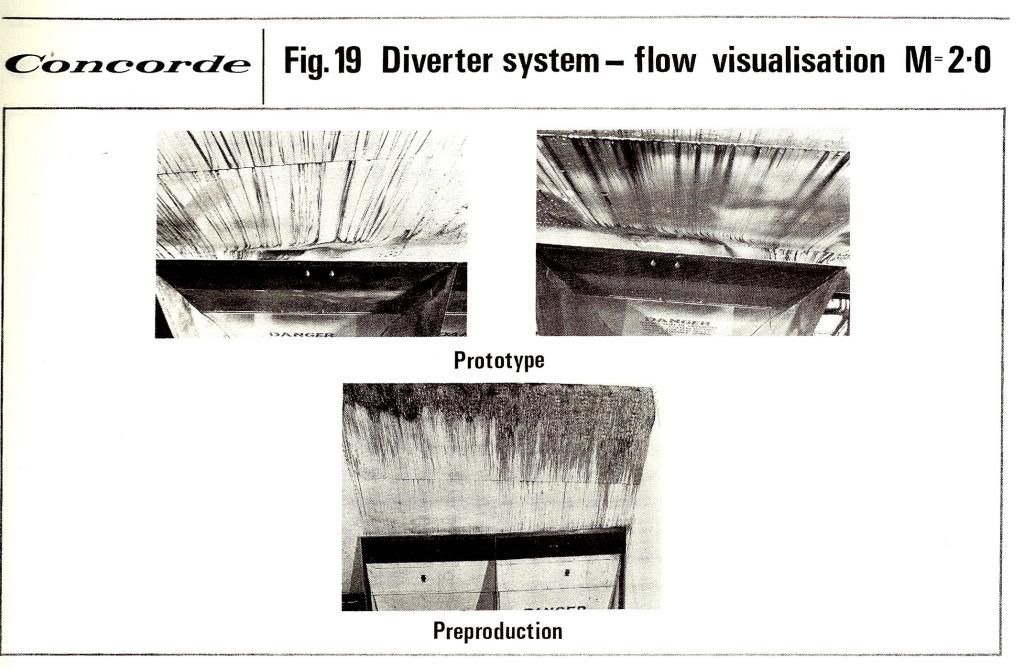
After the audience had asked Ted several questions about Concorde, Ted was then invited to ask the assembled USAF and Grumman personnel about the B1A programme, which would be honestly answered within the confines of security considerations. Ted said that he only had one real point to raise; 'I see that you are having major difficulties with wing boundary level interference at the engine inlets'. There was now a gasp of horror from various members of the USAF entourage, 'That's top secret, how the hell do you know that?'. Ted chortled 'it's easy, I saw that you have a multitude of precision pressure sensors under the wing forward of the intakes, that I assume are to measure the wing boundary flows'. Ted then unhelpfully comes up with 'Oh, and you've got the design completely wrong, your intakes are mounted sideways, and that allows the intake shocks to rip into the wing boundary layer, which will completely screw up your inlets at high supersonic speeds. That in my opinion is where most of your problems lie, with wing boundary level interference, but I think that your probes for measuring boundary layer are beautiful, we never had such things'. According to Ted there was not so much uproar at the meeting as much as horror and amazement that this (even then) quite senior in years British aerodynamicist had in a few seconds observed the fundamental design flaw in an otherwise superb but top secret aircraft, and could even see what they were trying to do about it. Ted was asked, 'so you had no boundary layer issues with Concorde then?' Oh we had a few, mainly with the diverter section mounted above the intake' replies Ted, 'but we sorted out the problems relatively easily. 'You said that you did not use precision pressure probes under the wing to measure boundary layer flow fields, so what DID you use then?', asks a Rockwell designer. 'Some oil lamps and diesel oil' replies Ted. The room is now filled with laughter from all those assembled, but Ted shouts 'I am serious, it's an old wind tunnel trick. You mix up diesel oil with lamp black, which you then paint over the wing surface forward of the intakes, where it forms a really thick 'goo', which sticks like glue to the wing'. The pilots in particular seem quite fascinated now, and Ted goes on; 'You fly in as cold air that you can find (we flew out of Tangiers and Casablanca) and flew as fast as you could. As the skin temperature increases with Mach number, the diesel and lamp black 'paint goo' becomes quite fluid, and start to follow the boundary layer flow field. You then decelerated as rapidly as possible, and the flow field 'picture; is frozen into the now again solid 'goo'. After we landed we just took lots of pictures, repeated the process for several flights until we know everything that we needed to know about our difficulties. After doing some redesign work we then repeated the exercise again several times, eventually proving that we'd got things right'. The audience asked Ted if this technique might help them with the B1A, but he replied that although it might help them with accurately illustrating the problem, in his opinion it was irelevant, 'because the intakes are the wrong way round'.
The B1A intake problems were never resolved, and in 1977 the project was cancelled, due to performance and cost issues. However the project was reborn as the B1B, not entering service until 1986. Although an amazing aircraft, with astonishing low altitude performance and capability, it is a fixed intake design, limited to Mach 1.6 at altitude. Ted was right it seems.
That evening, Ted gives his presentation speech to the assembled Test pilots, explaining in fair detail how the Concorde engine intake operated, and that the fact that unlike most other supersonic designs, the engine power was more or less freely variable at Mach 2 and above, even to the extent that if necessary the throttle could be closed all the way to the idle stop. There allegedly many gasps of amazement and disbelief in the room at this, and one B1A pilot was heard to ask his boss 'why the hell can't WE do that John'?. (It should be borne in mind here that the 'traditional' way of slowing down Mach 2+ aircraft is not to touch the throttles initially, and just cut the afterburners. If you don't do it this way many designs will drive into unstart and even flame-out).
After the audience had asked Ted several questions about Concorde, Ted was then invited to ask the assembled USAF and Grumman personnel about the B1A programme, which would be honestly answered within the confines of security considerations. Ted said that he only had one real point to raise; 'I see that you are having major difficulties with wing boundary level interference at the engine inlets'. There was now a gasp of horror from various members of the USAF entourage, 'That's top secret, how the hell do you know that?'. Ted chortled 'it's easy, I saw that you have a multitude of precision pressure sensors under the wing forward of the intakes, that I assume are to measure the wing boundary flows'. Ted then unhelpfully comes up with 'Oh, and you've got the design completely wrong, your intakes are mounted sideways, and that allows the intake shocks to rip into the wing boundary layer, which will completely screw up your inlets at high supersonic speeds. That in my opinion is where most of your problems lie, with wing boundary level interference, but I think that your probes for measuring boundary layer are beautiful, we never had such things'. According to Ted there was not so much uproar at the meeting as much as horror and amazement that this (even then) quite senior in years British aerodynamicist had in a few seconds observed the fundamental design flaw in an otherwise superb but top secret aircraft, and could even see what they were trying to do about it. Ted was asked, 'so you had no boundary layer issues with Concorde then?' Oh we had a few, mainly with the diverter section mounted above the intake' replies Ted, 'but we sorted out the problems relatively easily. 'You said that you did not use precision pressure probes under the wing to measure boundary layer flow fields, so what DID you use then?', asks a Rockwell designer. 'Some oil lamps and diesel oil' replies Ted. The room is now filled with laughter from all those assembled, but Ted shouts 'I am serious, it's an old wind tunnel trick. You mix up diesel oil with lamp black, which you then paint over the wing surface forward of the intakes, where it forms a really thick 'goo', which sticks like glue to the wing'. The pilots in particular seem quite fascinated now, and Ted goes on; 'You fly in as cold air that you can find (we flew out of Tangiers and Casablanca) and flew as fast as you could. As the skin temperature increases with Mach number, the diesel and lamp black 'paint goo' becomes quite fluid, and start to follow the boundary layer flow field. You then decelerated as rapidly as possible, and the flow field 'picture; is frozen into the now again solid 'goo'. After we landed we just took lots of pictures, repeated the process for several flights until we know everything that we needed to know about our difficulties. After doing some redesign work we then repeated the exercise again several times, eventually proving that we'd got things right'. The audience asked Ted if this technique might help them with the B1A, but he replied that although it might help them with accurately illustrating the problem, in his opinion it was irelevant, 'because the intakes are the wrong way round'.
The B1A intake problems were never resolved, and in 1977 the project was cancelled, due to performance and cost issues. However the project was reborn as the B1B, not entering service until 1986. Although an amazing aircraft, with astonishing low altitude performance and capability, it is a fixed intake design, limited to Mach 1.6 at altitude. Ted was right it seems.

EDIT : An additional hair-raiser, the tale of a test pilot who ejected from an SR-71 at almost full chat - and lived to tell the tale!:
SR-71 In-Flight Breakup
Last edited by DozyWannabe; 13th Feb 2013 at 00:40.
Join Date: Dec 2010
Location: Europe
Age: 88
Posts: 290
Likes: 0
Received 0 Likes
on
0 Posts
Brian,
That was really aimed at my response to Bill Lyman's questions not the original question.
I assumed he (Peter) was talking about Mach 3 conditions, but the subsonic conditions are of course as you describe them.
Since posting that contribution on ejector nozzles I have found another useful source which gives a good explanation of how they work:
NASA TM X- 67976
FACTORS WHICH INFLUENCE THE ANALYSIS AND DESIGN OF EJECTOR NOZZLES
by Bernhard H. Anderson, Aerospace Engineer
Lewis Research Center
Dozy
I have to disappoint your expectations I'm afraid - I will own up to sort of understanding intakes and a working knowledge of nozzles, but what goes on in the guts of the engine is a mystery to me - a bit like the dark arts of the rugby front rows For that sort of discussion you need real experts and I would, like gums, dearly like to have Dr Abernethy in on it!
I can confirm M2dudes story of Ted's US visit however - I got it from the horse's mouth. A bit off thread perhaps, but I thought folks might like to see the evidence ....
And of course that has nothing at all to be doing with Peter Kent's question
I assumed he (Peter) was talking about Mach 3 conditions, but the subsonic conditions are of course as you describe them.
Since posting that contribution on ejector nozzles I have found another useful source which gives a good explanation of how they work:
NASA TM X- 67976
FACTORS WHICH INFLUENCE THE ANALYSIS AND DESIGN OF EJECTOR NOZZLES
by Bernhard H. Anderson, Aerospace Engineer
Lewis Research Center
Dozy
I have to disappoint your expectations I'm afraid - I will own up to sort of understanding intakes and a working knowledge of nozzles, but what goes on in the guts of the engine is a mystery to me - a bit like the dark arts of the rugby front rows
For that sort of discussion you need real experts and I would, like gums, dearly like to have Dr Abernethy in on it!I can confirm M2dudes story of Ted's US visit however - I got it from the horse's mouth. A bit off thread perhaps, but I thought folks might like to see the evidence ....
Thread Starter
Join Date: Jan 2012
Location: Ontario
Age: 74
Posts: 82
Likes: 0
Received 0 Likes
on
0 Posts
bypass
Hi gums,
My understanding comes from reading the patent and other first-hand writings by Dr A.
Having calculated what was required to do the job, ie to sort out the compressor and then use the air to advantage in the a/b, his genius lay in how to do it with minimum carve-up to the existing a/b J58 and with minimum impact fitting it into the nacelle.
The six tubes did just that, requiring the minimum mods to as few existing engine components as possible. This equated to a very cost effective solution and very reliable I believe especially when you look at things like the expansion bellows on the tubes.
Glad you rate the thread.
Apparently, he discarded that design due to weight or something
Having calculated what was required to do the job, ie to sort out the compressor and then use the air to advantage in the a/b, his genius lay in how to do it with minimum carve-up to the existing a/b J58 and with minimum impact fitting it into the nacelle.
The six tubes did just that, requiring the minimum mods to as few existing engine components as possible. This equated to a very cost effective solution and very reliable I believe especially when you look at things like the expansion bellows on the tubes.
Glad you rate the thread.
Join Date: Jul 2002
Location: UK
Posts: 3,093
Likes: 0
Received 0 Likes
on
0 Posts
Indeed - though the difference in design brief is considerably greater once you get into specifics.
Concorde was designed to "supercruise" at M2 (i.e. without reheat/afterburner) because it was a hundred-seater airliner intended to provide supersonic service on the transatlantic and (initially) some of the old "Empire" routes. It had to use regular Jet A-1 (or equivalent) and the presence of passengers and luggage meant there was limited fuel capacity. Because of all these factors using reheat to sustain M2 was out of the question. The genius in Concorde's design was not so much in the speeds achieved as it was the way in which such speeds could be achieved and maintained over a long distance - with relatively remarkable fuel economy.
The SR-71's design brief was relatively straightforward - make it as fast as possible so that SA missiles of the type that downed Gary Powers' U-2 could not be a threat. Its payload was a pilot and high-tech imaging apparatus, meaning that it could also carry a boatload of fuel. Being the height of the Cold War, no expense was spared - even a type-specific fuel (JP-7) was developed for the project. As far as the propulsion was concerned, only a ramjet design was capable of sustaining M3, hence having the burners lit was a cornerstone of the brief from the beginning. The genius in this design was all about the speed, however special mention should be made of how pre-existing technology was leveraged and modified in a very economical way.
Apologies for the newbie talk on a thread that clearly has gone into the "expert" realm!
Join Date: Dec 2010
Location: Middle America
Age: 84
Posts: 1,167
Likes: 0
Received 0 Likes
on
0 Posts
Hi Gums,
Here is a cut-away of the TF30 turbojet afterburning engine.

Airflow leaving the fan is split into two flow streams, that which bypasses the core and is ducted (annular duct) to the afterburner, thought of to be a low flow bypass, and the flow stream entering the core of the engine.
The compressor section consists of a 9 stage low-pressure compressor, including the core portion of the three stage fan and a seven stage high-pressure compressor. Interestingly, there are 3 bleed points:
1. A 7th stage bleed which opens in flight at Mach numbers above 1.75
2. A 12th stage bleed which automatically opens to discharge air to the bypass duct when a surge condition is sensed
3. A 16th stage bleed to cool the high-pressure and low-pressure turbine blades.
The differences you experienced between the J57 engine and the F100 engine as to fuel burn and power can really be contributed to technology that came along over time. The J57s had cannular combustors, whereas the F100s had annular combustors which gave the burner folks much more design latitude and creativity to develop high combustor efficiencies. Also, the afterburner technology advanced in design, material capabilities and improved flow patterns resulting in enhanced fuel burn characteristics.
The A-7 aircraft used a non-afterburner TF30 engine in which the bleed systems were probably simplified verses the afterburning engine.
I think the problem with the J58 being modified to an annular bypass system would have been not only added weight, but all the external plumbing changes that would have been required, adding to the overall diameter of the engine.
Here is a cut-away of the TF30 turbojet afterburning engine.
Airflow leaving the fan is split into two flow streams, that which bypasses the core and is ducted (annular duct) to the afterburner, thought of to be a low flow bypass, and the flow stream entering the core of the engine.
The compressor section consists of a 9 stage low-pressure compressor, including the core portion of the three stage fan and a seven stage high-pressure compressor. Interestingly, there are 3 bleed points:
1. A 7th stage bleed which opens in flight at Mach numbers above 1.75
2. A 12th stage bleed which automatically opens to discharge air to the bypass duct when a surge condition is sensed
3. A 16th stage bleed to cool the high-pressure and low-pressure turbine blades.
The differences you experienced between the J57 engine and the F100 engine as to fuel burn and power can really be contributed to technology that came along over time. The J57s had cannular combustors, whereas the F100s had annular combustors which gave the burner folks much more design latitude and creativity to develop high combustor efficiencies. Also, the afterburner technology advanced in design, material capabilities and improved flow patterns resulting in enhanced fuel burn characteristics.
The A-7 aircraft used a non-afterburner TF30 engine in which the bleed systems were probably simplified verses the afterburning engine.
I think the problem with the J58 being modified to an annular bypass system would have been not only added weight, but all the external plumbing changes that would have been required, adding to the overall diameter of the engine.
Thread Starter
Join Date: Jan 2012
Location: Ontario
Age: 74
Posts: 82
Likes: 0
Received 0 Likes
on
0 Posts
Brian,
He's referring to M2.2 and M3+ from his Table 1 of 'Propulsive thrust distribution'.
It's on page 672 of the paper.
Thanks for the intake patent.
From the brief quote peter I don't understand as to whether David is talking about cruise or low speed
It's on page 672 of the paper.
Thanks for the intake patent.
I flew the Allison TF-41 in the SLUF, not the TF30 of the early variants, and I understand that the Brits added a "re-heat" to the sucker ( Spey) for their F-4 model. Only thing that sticks with me was how efficient that motor was.
The A-7D and A-7E used the licensed Spey - the TF-41.
I am wondering about the comment that the J-58 was already a prototype that needed to have the bypass ducts for the Blackbirds. I realize that by the time the Blackbird was in the design stage that somebody somewhere was already working on a high thrust motor. I also realize that development of a totally new motor would have been a bitch to test and employ.
Hats off to the Concorde folks that had a "super cruise" jet as early as they did. That thing not only looked good but flew good, maybe great.
Thread Starter
Join Date: Jan 2012
Location: Ontario
Age: 74
Posts: 82
Likes: 0
Received 0 Likes
on
0 Posts
Clive,
My original question basically revolved around the above interpretation of mine, ie the heating up of the induced flow took place before it got to the ejector,ie heating it up with max a/b meant? through heat transfer from the red-hot outside of the a/b duct....... or was the author referring to something else?
I see in
page 3 'However, it is evident that heating the secondary
inlet flow would result in a decrease in nozzle
efficiency.'
I don't know if I have taken it out of context but understand it to say that any heat transfer into the nacelle secondary flow upstream of the ejector would not be good? theoretically at any rate, but perhaps not significant in practice.
Don't know if you can make any sense of this rambling.
Q referring specifically to 'is inducing flow and heating it up with maximum afterburner'
I take this to refer to the induced secondary flow which flows over the red-hot afterburner casing and the intimation that this is significant in producing thrust. However due to the high air flow rate (1/3 intake entry flow) and it being a poor design of heat exchanger would the heat transfer really be significant (ie per lb/sec)?
I take this to refer to the induced secondary flow which flows over the red-hot afterburner casing and the intimation that this is significant in producing thrust. However due to the high air flow rate (1/3 intake entry flow) and it being a poor design of heat exchanger would the heat transfer really be significant (ie per lb/sec)?
I see in
NASA TM X- 67976
FACTORS WHICH INFLUENCE THE ANALYSIS AND DESIGN OF EJECTOR NOZZLES
FACTORS WHICH INFLUENCE THE ANALYSIS AND DESIGN OF EJECTOR NOZZLES
inlet flow would result in a decrease in nozzle
efficiency.'
I don't know if I have taken it out of context but understand it to say that any heat transfer into the nacelle secondary flow upstream of the ejector would not be good? theoretically at any rate, but perhaps not significant in practice.
Don't know if you can make any sense of this rambling.
Join Date: Jul 2002
Location: UK
Posts: 3,093
Likes: 0
Received 0 Likes
on
0 Posts
Thread Starter
Join Date: Jan 2012
Location: Ontario
Age: 74
Posts: 82
Likes: 0
Received 0 Likes
on
0 Posts
Hi gums,
Your comments prompted me to look up a couple of things.
"During (TF-41) development testing with M61 gun and missile firing the only sign of engine malfunction was a slight pop surge when missiles were fired simultaneously. Since the engine recovered immediately with no pilot action, the test was deemed to be satisfactory.
The ultimate handling demonstration consisted of gross weight launches with fully degraded catapult. The engine was surge free with maximum steam ingestion, in contrast to violent surges and flame-out on the TF-30."
Have you always had carefree throttle-handling on all your planes or were there restrictions in the old days?
I flew the Allison TF-41 in the SLUF, not the TF30 of the early variants, and I understand that the Brits added a "re-heat" to the sucker ( Spey) for their F-4 model. Only thing that sticks with me was how efficient that motor was.
"During (TF-41) development testing with M61 gun and missile firing the only sign of engine malfunction was a slight pop surge when missiles were fired simultaneously. Since the engine recovered immediately with no pilot action, the test was deemed to be satisfactory.
The ultimate handling demonstration consisted of gross weight launches with fully degraded catapult. The engine was surge free with maximum steam ingestion, in contrast to violent surges and flame-out on the TF-30."
Have you always had carefree throttle-handling on all your planes or were there restrictions in the old days?
This is getting off topic, but since you asked....
The Pratts seemed more sensitive to rapid throttle movements until they implemented the super duper electronic fuel control systems. The GE motors were lots less sensitive, and you could slam the throttle to max or idle with no problems.
The TF-41, aka Spey, was great about rapid throttle movement, but it took awhile to respond. So in formation you pushed up/pulled back and then resumed the original throttle setting once you saw movement. The F100 in the Viper was much quicker on the response.
One characteristic about the Pratts was they did not like going to burner under a gee load. Saw it with the J57 and then the F100 years later.
But back to the main topic, huh?
I still wonder about an annular duct as we had on the fans I flew. Maybe some intake or bleed doors, but use all that fresh air back in the burner.
Join Date: Aug 2003
Location: Sale, Australia
Age: 80
Posts: 3,832
Likes: 0
Received 0 Likes
on
0 Posts
peter, I think perhaps the "induced flow by the engine" may be a reflection of the Ben Rich statement "the engine compressor is just a pump to keep the inlet alive". If you think of it in those terms the engine is indeed "inducing flow", and of course that air is being heated by the afterburner.
One part of the paper I'm having trouble getting my head around is the statement
Why? Most of the range charts include the figures for a minimum afterburner setting. The base engine is operating at military power whenever a afterburner setting is selected. Selecting some range figures, min A/B, Mach 3.2 cruise, -66.8�C OAT, 105,000 pounds AUW, 72,600 feet, specific range 47.5 nautical miles/1,000 lbs fuel. The flight manual notes under descent procedures that at military power, Mach 3.2, 350KEAS, the angle of descent is approx 1�. Confused is an understatement. Perhaps JF with his expertise may jump in.
One part of the paper I'm having trouble getting my head around is the statement
If the AB is reduced to minimum AB, the engine would actually be dragging on the engine mounts at high Mach numbers.
Join Date: Aug 2011
Location: Grassy Valley
Posts: 2,074
Likes: 0
Received 0 Likes
on
0 Posts
Hello CliveL
I did not mention "bleed drag". My comment was based on Dr. Bob's PATENT, in which he fully describes the purpose of his bleed pipes, and his offer of a TurboRamjet solution: which he discards, as "too heavy".
Part of his claims, specifically, was to offer his bleed system as having a twofold cooling effect. First, reducing Temperature at the vicinity of bleed "entry", and secondly, upon re-introduction to the ejector, cooling the AB "LINER".
I DID infer that relative to his claim of partial RAMJET gains, he was linking this increase of thrust to a prior DECREASE in choke pressure.
What I think is a logical inference from that is that he is relocating what can be thought of as RAM EFFECT, (choke), from the compressor to the EJECTOR, via this bleed scheme.
That is all.
But I don't understand what you mean when you talk about 'bleed drag' What bleed? What sort of drag? How do you think reducing 'drag' (an external force) could 'unleash power from the Bypass' (whatever that might mean)
Part of his claims, specifically, was to offer his bleed system as having a twofold cooling effect. First, reducing Temperature at the vicinity of bleed "entry", and secondly, upon re-introduction to the ejector, cooling the AB "LINER".
I DID infer that relative to his claim of partial RAMJET gains, he was linking this increase of thrust to a prior DECREASE in choke pressure.
What I think is a logical inference from that is that he is relocating what can be thought of as RAM EFFECT, (choke), from the compressor to the EJECTOR, via this bleed scheme.
That is all.
Join Date: Dec 2010
Location: Europe
Age: 88
Posts: 290
Likes: 0
Received 0 Likes
on
0 Posts
Lyman
Where in the patent does he claim this please - I cannot find such a claim. The nearest I see is p5 (27~30) but that is not at all the same thing. He is talking there of the fact that the bleed air is lower temperature than the burner and that helps reduce weight of the bleed tubes.
Part of his claims, specifically, was to offer his bleed system as having a twofold cooling effect. First, reducing Temperature at the vicinity of bleed "entry",