


Blackbird's thrust question

Join Date: Aug 2011
Location: Grassy Valley
Posts: 2,074
Likes: 0
Received 0 Likes
on
0 Posts
Thanks Clive, looking....
From PATENT 3344606
PAGE ONE. Paragraph 2
"...performance deteriorates primarily because of ram air temperature rise...at high supersonic speeds..."
PAGE ONE Paragraph 1
"...air is bled from an intermediate compressor stage...to be reheated in afterburner....."
From PATENT 3344606
PAGE ONE. Paragraph 2
"...performance deteriorates primarily because of ram air temperature rise...at high supersonic speeds..."
PAGE ONE Paragraph 1
"...air is bled from an intermediate compressor stage...to be reheated in afterburner....."
Last edited by Lyman; 14th Feb 2013 at 15:04.

Join Date: Dec 2010
Location: Europe
Age: 88
Posts: 290
Likes: 0
Received 0 Likes
on
0 Posts
Peter
That's the way I interpreted it also, and why I initially suggested that lighting up the burner would induce more secondary flow because of the primary jet temperature increase. Now I'm not so sure 
Using Peter Law's data and the SR 71 FM I get
Compressor inlet temp 427C (700K) this is also the cooling air entry temp.
Turbine exit temp 795C (1068K) this would be Tj with no afterburner
Tj Primary nozzle temp with A/B 1760C (2033K)
Secondary temp at nozzle A/B on 649C (922K)
Ps/Pj 0.29
I am 'guesstimating' the secondary temp at the nozzle to be around 550C (823K) when the afterburner is switched off.
The nozzle efficiency seems to peak at around a corrected secondary flow ratio of 0.08. Keeping that for the moment those temperatures give secondary (cooling)/primary mass flow ratios of 0.09 without A/B and 0.12 with A/B, which is consistent with my original explanation even though a lot lower than the 1/3 intake flow you mentioned originally. BUT, the primary nozzle area would increase when A/B comes on, which would reduce the secondary flow ratio from 0.08 to I don't know what (yet!). If the original quote is correct then this effect would be lower than the heating effect.
It might be evident to the author, but it sure ain't to me 
Part of the problem is that there are so many variables and he doesn't say what he is keeping constant with that remark. It certainly reads as if heating the secondary would be bad news, but everything else being unchanged that would increase the secondary flow ratio so the result would depend on which side of the optimum (mu = 0.08) you started.
Brian
Just a suggestion - when one reduces A/B flow on the SR71 the rpm and engine mass flow stay unchanged, as does the intake entry flow. Following up my argument in an earlier posting that would imply that although the actual engine contribution to thrust was dropping (from 13% towards zero) the intake, and to a lesser extent the nozzle, thrusts would be little changed. Could it be that at minimum afterburner the engine is, in fact, behaving like that apocryphal pump which connects the two?
Q referring specifically to 'is inducing flow and heating it up with maximum afterburner'
I take this to refer to the induced secondary flow which flows over the red-hot afterburner casing and the intimation that this is significant in producing thrust. However due to the high air flow rate (1/3 intake entry flow) and it being a poor design of heat exchanger would the heat transfer really be significant (ie per lb/sec)? My original question basically revolved around the above interpretation of mine, ie the heating up of the induced flow took place before it got to the ejector,ie heating it up with max a/b meant? through heat transfer from the red-hot outside of the a/b duct....... or was the author referring to something else?
I take this to refer to the induced secondary flow which flows over the red-hot afterburner casing and the intimation that this is significant in producing thrust. However due to the high air flow rate (1/3 intake entry flow) and it being a poor design of heat exchanger would the heat transfer really be significant (ie per lb/sec)? My original question basically revolved around the above interpretation of mine, ie the heating up of the induced flow took place before it got to the ejector,ie heating it up with max a/b meant? through heat transfer from the red-hot outside of the a/b duct....... or was the author referring to something else?
Using Peter Law's data and the SR 71 FM I get
Compressor inlet temp 427C (700K) this is also the cooling air entry temp.
Turbine exit temp 795C (1068K) this would be Tj with no afterburner
Tj Primary nozzle temp with A/B 1760C (2033K)
Secondary temp at nozzle A/B on 649C (922K)
Ps/Pj 0.29
I am 'guesstimating' the secondary temp at the nozzle to be around 550C (823K) when the afterburner is switched off.
The nozzle efficiency seems to peak at around a corrected secondary flow ratio of 0.08. Keeping that for the moment those temperatures give secondary (cooling)/primary mass flow ratios of 0.09 without A/B and 0.12 with A/B, which is consistent with my original explanation even though a lot lower than the 1/3 intake flow you mentioned originally. BUT, the primary nozzle area would increase when A/B comes on, which would reduce the secondary flow ratio from 0.08 to I don't know what (yet!). If the original quote is correct then this effect would be lower than the heating effect.
I see in
Quote:
NASA TM X- 67976
FACTORS WHICH INFLUENCE THE ANALYSIS AND DESIGN OF EJECTOR NOZZLES
page 3 'However, it is evident that heating the secondary
inlet flow would result in a decrease in nozzle
efficiency.'
I don't know if I have taken it out of context but understand it to say that any heat transfer into the nacelle secondary flow upstream of the ejector would not be good? theoretically at any rate, but perhaps not significant in practice.
Part of the problem is that there are so many variables and he doesn't say what he is keeping constant with that remark. It certainly reads as if heating the secondary would be bad news, but everything else being unchanged that would increase the secondary flow ratio so the result would depend on which side of the optimum (mu = 0.08) you started.
Brian
Just a suggestion - when one reduces A/B flow on the SR71 the rpm and engine mass flow stay unchanged, as does the intake entry flow. Following up my argument in an earlier posting that would imply that although the actual engine contribution to thrust was dropping (from 13% towards zero) the intake, and to a lesser extent the nozzle, thrusts would be little changed. Could it be that at minimum afterburner the engine is, in fact, behaving like that apocryphal pump which connects the two?
Last edited by CliveL; 14th Feb 2013 at 15:04.
Join Date: Aug 2011
Location: Grassy Valley
Posts: 2,074
Likes: 0
Received 0 Likes
on
0 Posts
Let me do it this way. From a reading of the first two paragraphs of the PATENT application I infer that The Applicant proposes to reduce temperature and Pressure in the compressor, caused by Ram Air effect at high supersonic speeds, by creating a bleeds scheme that redirects some of the gaspath to the Ejector.
That is my conclusion. I am happy with it.
That is my conclusion. I am happy with it.
Last edited by Lyman; 14th Feb 2013 at 16:27.

Join Date: Aug 2003
Location: Sale, Australia
Age: 80
Posts: 3,832
Likes: 0
Received 0 Likes
on
0 Posts
As I intimated in my post #138, I was, and remain so, confused by a couple of sentences in the "F-12 Series Aircraft Propulsion System Performance and Development" by David H. Campbell, so sent an email to Doctor Abernethy for enlightenment.
1. If the AB is reduced to minimum AB, the engine would actually be dragging on the engine mounts at high Mach numbers.
2. Further reduction of engine thrust below military power will result in no propulsive thrust on the aircraft.
The good Doctors answer
Reading David Campbells paper one would assume it to be a steady state condition he is referring to, rather than transient.
Well, I guess we'll just continue to argue the toss.
1. If the AB is reduced to minimum AB, the engine would actually be dragging on the engine mounts at high Mach numbers.
2. Further reduction of engine thrust below military power will result in no propulsive thrust on the aircraft.
The good Doctors answer
1. This is a transient condition and is very complex. Most of the thrust at high Mach comes from the inlet, not the engine. Many years ago I took a course for a year on supersonic inlets and it was very difficult. Same answer for 2.
Sorry ....not much help.....
Sorry ....not much help.....
Well, I guess we'll just continue to argue the toss.
Thread Starter
Join Date: Jan 2012
Location: Ontario
Age: 74
Posts: 82
Likes: 0
Received 0 Likes
on
0 Posts
Clive,
I'll find where I got that. I'm sure there is a lot of other stuff that goes with it that may help.
Here it is, Fig 12 at M2.8
Access forbidden!
What now?
the 1/3 intake flow you mentioned originally
Here it is, Fig 12 at M2.8
Access forbidden!
What now?
Last edited by peter kent; 15th Feb 2013 at 01:48.
Join Date: Dec 2010
Location: Europe
Age: 88
Posts: 290
Likes: 0
Received 0 Likes
on
0 Posts
Peter
There is indeed a lot of stuff in the link you posted which will be a lot of help.
Many thanks
I'm sure there is a lot of other stuff that goes with it that may help.
Here it is, Fig 12 at M2.8
Here it is, Fig 12 at M2.8
Many thanks
Join Date: Aug 2011
Location: Grassy Valley
Posts: 2,074
Likes: 0
Received 0 Likes
on
0 Posts
Hi peter
Thanks for the reply. I think it is possible to see it both ways. From the language in the patent document, we see the bleed enters the AB to cool the liner, but that is only one of the benefits claimed. Cooling the liner from the inside does not relate to heating the secondary flow outside and around it. Those are separate issues, imo. "Cooling" is counterintuitive, when thrust is increased, right?
The benefit to Thrust lies in the added mass, not its increase/decrease in temperature. ANY increase in mass in the ejector wil increase thrust, right?
The inventor references "full throttle", so "added fuel" is off the table. My reference to increase in SFC has to do with this added mass. Is it because in this added mass is added Oxygen? Better (more complete) combustion? One would think so.
Added mass, also yes?
As to the early reference to ram air effect? The inventor's juxtaposition of this drawback with the reference to "bleed system" is self explanatory, especially when considered in light of his later reference to his "solution"?
thanks again...
edit... At some point, it would be interesting to extrapolate this platform's potential to became an actual RamJet. I have drawings.....
Last edited by Lyman; 15th Feb 2013 at 13:36.
Thread Starter
Join Date: Jan 2012
Location: Ontario
Age: 74
Posts: 82
Likes: 0
Received 0 Likes
on
0 Posts
Hi gums,
TurbineD said it all with, for example
I have found 2 photographs which illustrate the plumbing nightmare and how tight it was to get 2 of the tubes out of the compressor case. For some reason I am not allowed to add attachments to my posts.
You can see them if you google J58 images though.
I still wonder about an annular duct
all the external plumbing changes that would have been required
You can see them if you google J58 images though.
Join Date: Dec 2010
Location: Middle America
Age: 84
Posts: 1,167
Likes: 0
Received 0 Likes
on
0 Posts
Hi Peter,
The best photo I think you saw, illustrating the plumbing problem, is from AirpowerWorld:
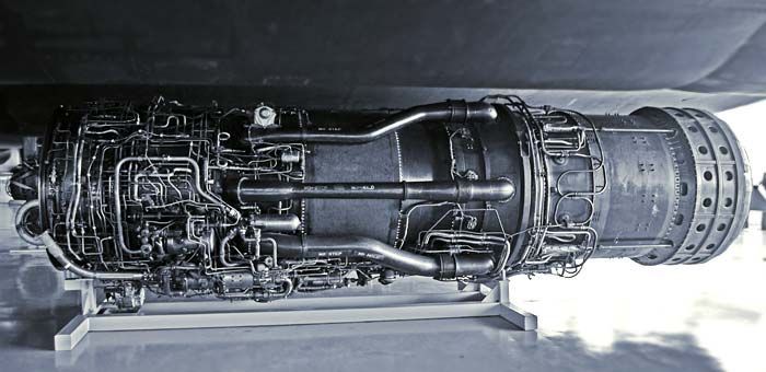
It is the plumbing under the engine that if an annular bypass were to have been used, would have no place to go but outward, increasing the OD of the engine.
The best photo I think you saw, illustrating the plumbing problem, is from AirpowerWorld:
It is the plumbing under the engine that if an annular bypass were to have been used, would have no place to go but outward, increasing the OD of the engine.
Join Date: Aug 2011
Location: Grassy Valley
Posts: 2,074
Likes: 0
Received 0 Likes
on
0 Posts
Hello TD..
I think if that were the case, the annulus could have been severed, into two separate axial ducts, allowing for the retention of the plumbing.
A better solution would have been to reroute the plumbing into the wing, around the annular duct. The annulus would not have to be much thicker in profile than the "pipes" themselves, the bleed accounted for 20 percent flow. Keeping the same depth as the pipes, an annular duct could have surrounded the case, and been ten times the cross section of the fitted bleeds.
The inventor rejected the ducting as "too heavy". In the patent......
It is the plumbing under the engine that if an annular bypass were to have been used, would have no place to go but outward, increasing the OD of the engine.
A better solution would have been to reroute the plumbing into the wing, around the annular duct. The annulus would not have to be much thicker in profile than the "pipes" themselves, the bleed accounted for 20 percent flow. Keeping the same depth as the pipes, an annular duct could have surrounded the case, and been ten times the cross section of the fitted bleeds.
The inventor rejected the ducting as "too heavy". In the patent......
Thread Starter
Join Date: Jan 2012
Location: Ontario
Age: 74
Posts: 82
Likes: 0
Received 0 Likes
on
0 Posts
Clive,
Extra background, the F-12 with chines at M3 had L/D about 6.6 as you figured for the SR-71.
See Fig 6 "F-12 Series Aircraft Aerodynamic and Thermodynamic Design in Retrospect" Ben Rich.
The following is a previous post of mine. Is there any merit in my "schoolboy" plot and conclusions? I know it's just observed FF and not sfc, etc but was I just lucky or have I misinterpreted things? The range charts I got from his book.
Thanks.
ref Col Graham:
"The faster it flew the more efficient it became. For example the range charts show.."
If we plot FF v Mn from the range charts we get a steady increase in FF peaking at M3.0 then a dip to M3.15 and increasing again at M3.2 (for all but one condition).
Isn't this FF trough an indication that the whole aircraft has finally reached its design point. ie it's more efficient at M3.15 than at M3.0 or M3.2?
eg the spike shock doesn't meet the cowl lip until the design speed, the terminal shock is now correctly positioned with minimum intensity, etc.
eg the nacelle drag is a minimum. ref Col graham "Any time the SR-71 was at of above M3.05 the aft bypass was always placed in the CLOSE position."
eg the engine/afterburner/exhaust expansion are all where they should be.
Join Date: Dec 2010
Location: Middle America
Age: 84
Posts: 1,167
Likes: 0
Received 0 Likes
on
0 Posts
Lyman,
This is how it is done:
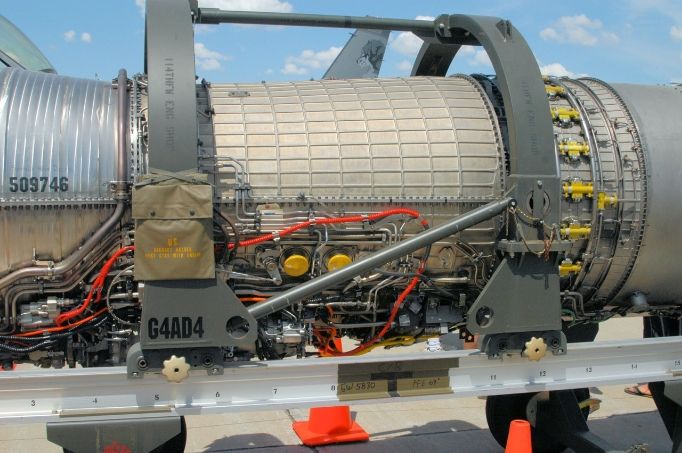
The OD of the annular bypass duct is the golden colored section. Note the plumbing is on the outside of the duct. This happens to be an image of a F110-129, the F100-PW-229 engine is the same.
The idea is to permit the engine to be slid into the hole and have predetermined connection points for fuel, electrical and other connections made through access panels in the nacelle, the less number of panels, the better. Your solution would be an absolute nightmare from both an install/uninstall basis for any engine, be it nacelle or fuselage contained. As I previously said, patents do not tell all that might be known, only the minimum necessary for the invention. The next engine out of the chute at P&W was the TF30 that used the annular approach for the F-111.
I think this thread is really about the technical understanding of the aero, thermo and complexity of the inlet system enabling the engine to achieve the power needed to propel the aircraft to Mach 3 or more and not so much about the technology of the engine itself.
This is how it is done:
The OD of the annular bypass duct is the golden colored section. Note the plumbing is on the outside of the duct. This happens to be an image of a F110-129, the F100-PW-229 engine is the same.
The idea is to permit the engine to be slid into the hole and have predetermined connection points for fuel, electrical and other connections made through access panels in the nacelle, the less number of panels, the better. Your solution would be an absolute nightmare from both an install/uninstall basis for any engine, be it nacelle or fuselage contained. As I previously said, patents do not tell all that might be known, only the minimum necessary for the invention. The next engine out of the chute at P&W was the TF30 that used the annular approach for the F-111.
I think this thread is really about the technical understanding of the aero, thermo and complexity of the inlet system enabling the engine to achieve the power needed to propel the aircraft to Mach 3 or more and not so much about the technology of the engine itself.
Join Date: Aug 2011
Location: Grassy Valley
Posts: 2,074
Likes: 0
Received 0 Likes
on
0 Posts
Dr. Abernethy did not have the luxury of the "white sheet". Who could keep up with Kelly Johnson? (the airframer).....
From my understanding, the geometry was done, the engine built. Dr. Abernethy's invention was an elegant solution to a "how do we do this"?
Thanks for your cool photos!
The F-111 was (initially) intended for carrier ops, as I recall. One of the first test pilots: "There isn't enough thrust in the free world to get this turkey off a carrier deck...."
Last edited by Lyman; 15th Feb 2013 at 17:13.
Join Date: Dec 2010
Location: Europe
Age: 88
Posts: 290
Likes: 0
Received 0 Likes
on
0 Posts
Peter,
That figure does indeed show the TOTAL bleed to be around 1/3 intake capture, but the bit we are interested in is the shock trap bleed which becomes the cooling air and the eventual secondary nozzle air. That bleed is 5% of the intake capture, but since at that point the engine flow is only 75% of the intake capture the secondary airflow would have been 6.7% engine flow. Less than my estimate for M 3.0 from Peter Law's data but reasonably close all things considered.
There is something like that going on, although one needs to be careful what data one plots. At constant altitude and weight for example the fuel flow increases steadily with increasing Mach No up to Mach 3 then rises much less up to M 3.15 then resumes its inexorable increase. But the specific range is better at M 3.15 than at either M 3.0 or M 3.2.
It certainly looks as if the powerplant gets close to its maximum efficiency around Mach 3.1~3.15 probably, as you say, because it gets to maximum capture (shock on lip) conditions and the engine can swallow enough air to eliminate the need for any forward bypass bleed. Maybe some of the other references you have posted will show up why.....
Here it is, Fig 12 at M2.8
The following is a previous post of mine. Is there any merit in my "schoolboy" plot and conclusions? I know it's just observed FF and not sfc, etc but was I just lucky or have I misinterpreted things? The range charts I got from his book.
It certainly looks as if the powerplant gets close to its maximum efficiency around Mach 3.1~3.15 probably, as you say, because it gets to maximum capture (shock on lip) conditions and the engine can swallow enough air to eliminate the need for any forward bypass bleed. Maybe some of the other references you have posted will show up why.....
Last edited by CliveL; 15th Feb 2013 at 18:14.
Join Date: Aug 2003
Location: Sale, Australia
Age: 80
Posts: 3,832
Likes: 0
Received 0 Likes
on
0 Posts
Re max/cruise Mach. The flight manual quotes
Perhaps you can draw some conclusions Clive from the following numbers (from the flight manual).
Minimum afterburner thrust at sea level is approx 85% of maximum afterburner thrust and approx 55% at high altitude.
Military thrust at sea level is approx 70% of maximum thrust. At high altitude military thrust is approx 28% of the maximum available.
Some temperature and pressure ratio (compared to ambient) engine numbers.
Compressor face ccccccc427/38.8
Compressor discharge 1ic704/
4th stage bypass tubes i566/
Combustor cccccccccci1093/112
Turbine ccccccccccccic788/35.5
Afterburner ccccccccc1760/
Ejector secondary ccccccc/9.1 (flow accelerated from Mach .4 to 3.0)
Exhaust cccccccccccci649/31.2
Following is a plot of thrust (and drag of the spike) provided by the various engine components at various speeds with max A/B.

It would be interesting to get hold of Brown, William H. �J58/SR-71 Propulsion Integration,� Studies in Intelligence 26:2 (Summer 1982), 15-23. Probably be able to shed some light.
Mach 3.2 is the design Mach number. Mach 3.17 is the maximum scheduled cruise speed recommended for normal operations However, when authorised by the Commander, speeds up to Mach 3.3 may be flown if the limit CIT of 427�C is not exceeded.
Minimum afterburner thrust at sea level is approx 85% of maximum afterburner thrust and approx 55% at high altitude.
Military thrust at sea level is approx 70% of maximum thrust. At high altitude military thrust is approx 28% of the maximum available.
Some temperature and pressure ratio (compared to ambient) engine numbers.
Compressor face ccccccc427/38.8
Compressor discharge 1ic704/
4th stage bypass tubes i566/
Combustor cccccccccci1093/112
Turbine ccccccccccccic788/35.5
Afterburner ccccccccc1760/
Ejector secondary ccccccc/9.1 (flow accelerated from Mach .4 to 3.0)
Exhaust cccccccccccci649/31.2
Following is a plot of thrust (and drag of the spike) provided by the various engine components at various speeds with max A/B.
It would be interesting to get hold of Brown, William H. �J58/SR-71 Propulsion Integration,� Studies in Intelligence 26:2 (Summer 1982), 15-23. Probably be able to shed some light.
Join Date: Dec 2010
Location: Europe
Age: 88
Posts: 290
Likes: 0
Received 0 Likes
on
0 Posts
Brian
There is a lot of data there Brian, it will take a while to work through it!
Some interesting Concorde M 2.0 numbers for comparison with that chart:
Zone 1~2 12% drag
Zone 2~3 75% thrust
Zone 3~4 8% thrust (dry)
Zone 4~5 29% thrust
Very similar aren't they!
Perhaps you can draw some conclusions Clive from the following numbers (from the flight manual).
Some interesting Concorde M 2.0 numbers for comparison with that chart:
Zone 1~2 12% drag
Zone 2~3 75% thrust
Zone 3~4 8% thrust (dry)
Zone 4~5 29% thrust
Very similar aren't they!
Last edited by CliveL; 16th Feb 2013 at 09:56.