


Silhouette challenge


Join Date: Oct 2008
Location: Wales, UK
Age: 65
Posts: 6,062
Likes: 0
Received 0 Likes
on
0 Posts
Sorry not had a chance to pay attention to this,
So just to be clear:
- it has a single ducted fan
- it never flew
- it was a project.
I presume in addition to the ducted fan there is also a shrouded pusher prop at the rear?
So just to be clear:
- it has a single ducted fan
- it never flew
- it was a project.
I presume in addition to the ducted fan there is also a shrouded pusher prop at the rear?

Join Date: May 2010
Location: EU
Age: 82
Posts: 5,505
Likes: 0
Received 0 Likes
on
0 Posts
Nozzle-forming flaps move.
Edit: Maybe the "ducted fans" is misleading. They are four turbofans. More like "powered wings".
Edit: Maybe the "ducted fans" is misleading. They are four turbofans. More like "powered wings".
Last edited by RegDep; 16th Mar 2011 at 12:17.
Join Date: May 2010
Location: EU
Age: 82
Posts: 5,505
Likes: 0
Received 0 Likes
on
0 Posts
Skytrain has it:
Skytrain has the thread!
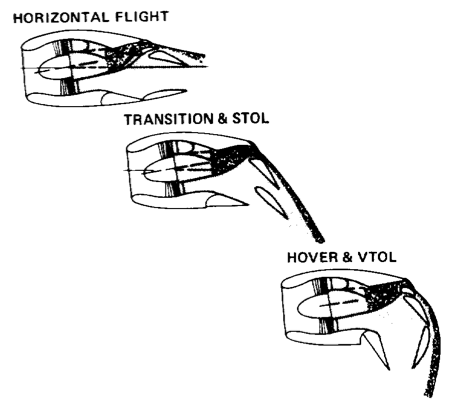
A medium-speed concept studied by General Dynamics, Fort Worth Division, features a powered lift system referred to as ABLE (Advanced Blown Lift Enhancement). The heart of this system is a "lifting nacelle" integrated into the wing that vectors the thrust of turbofan engines by using a series of movable flaps to make up the nozzle as illustrated in Fig. 23. One flap forms the upper surface of the two-dimensional nozzle, and two flaps form the lower surface. The upper flap has two slots. The upper forward slot forms the high-aspect-ratio nozzle for the turbine engine exhaust, and the upper aft slot is a boundary layer control slot. The intent is to energize the external boundary layer and thus maintain attached airflow over the "lifting nacelles" to produce significant gains in STOL and transition performance and in aircraft controllability in these modes of flight. In forward flight, the flaps are arranged as shown on the left in Fig. nn, and in transition flight the flaps are deflected into intermediate positions as in the center of the figure. In hover flight the lower aft flap becomes a part of the aft wall of a vertical-thrust nozzle. The lower forward flap becomes the forward wall of the nozzle and provides a generous radius of the inside of the turn to reduce separation.
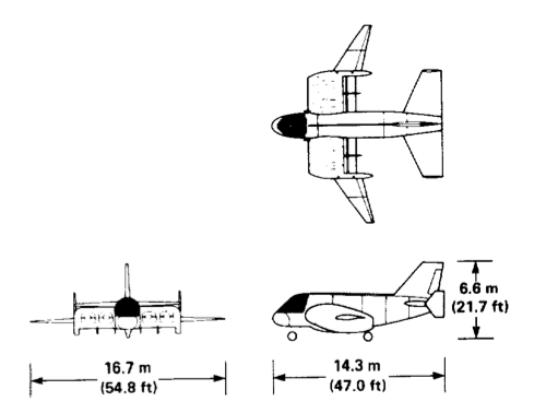
This propulsive lift system has been used in a configuration (A-311). A three-view sketch is shown in Fig. (attached).
Four turbofan engines are used in the lifting nacelles of configuration A-311. The fans are cross-shafted together using bevel gears in the fan nose bullets for engine-out considerations. Two load compressors are mounted between the inboard engines and the fuselage and are driven directly from the cross shaft. These compressors provide compressed air to the pitch trim/control system in the aft fuselage. This compressed air drives two air turbines which in turn drive two fans. The fan exhaust passes through dual nozzles which can be aimed up or down using a movable deflection system. Roll control in hover is achieved by biasing the thrust of the main engines either left or right through the cross shaft. Yaw control in hover is achieved by differentially deflecting the main engine nozzle flaps fore and aft on opposite sides of the aircraft.
Skytrain has the thread!
Join Date: May 2010
Location: EU
Age: 82
Posts: 5,505
Likes: 0
Received 0 Likes
on
0 Posts
Sure has been....


It looked first to my untrained eye like cross-shafted ducted fans......
Join Date: Oct 2008
Location: Wales, UK
Age: 65
Posts: 6,062
Likes: 0
Received 0 Likes
on
0 Posts
Thanks RD. An interesting concept. Having got nowhere with ducted fans, lift fans or shrouded props, when I saw your comment about "nozzle forming flaps" I did a search for "air blown flaps", and bingo!  .
.
Here's the next one....no hidden extras, what you see is what you get:

. Here's the next one....no hidden extras, what you see is what you get:

Join Date: Oct 2008
Location: Wales, UK
Age: 65
Posts: 6,062
Likes: 0
Received 0 Likes
on
0 Posts
Evening Graeme...makes life a hell of a lot easier...the number of times I used to keep hitting refresh to get a set of characters I could read!
Yes, its the Aviatika-MAI 900 from Russia

Your control Graeme.
Yes, its the Aviatika-MAI 900 from Russia
Your control Graeme.
Thanks Ken.
Everyone seems to be into projects lately, so here goes. According to the article it shares a similar engineering design with the Rockwell B-1; namely a rotary bomb dispenser...
Another Boulton Paul project!

Everyone seems to be into projects lately, so here goes. According to the article it shares a similar engineering design with the Rockwell B-1; namely a rotary bomb dispenser...
Another Boulton Paul project!
