


Theory on lift

Join Date: Aug 2011
Location: Grassy Valley
Posts: 2,074
Likes: 0
Received 0 Likes
on
0 Posts
Hi HN
Point of View without question. But my comment is framed from the Bernoulli position, that locale is all important, to the exclusion of logic, and entertaining assumptions that require the suspension of physics.....
Inviscid, ideal liquid, "virtual scoop", Accelerated airmass, etc....
I thought the global view was reserved for the Physics shair at Oxford, not Bernoulli?
Am I winning you over?

Join Date: Jun 2011
Location: france
Posts: 760
Likes: 0
Received 0 Likes
on
0 Posts
1. ...take care to that mistake (sleep better !)
Drag and Lift are not connected to gravity direction, but to airspeed direction.
Weight and Power come in balance (or unbalance) with Drag and Lift.
2. For these who find the discussion too difficult, stay with Gentry
3. For our PPRuNe's Flight Gods, perhaps they don't understand fractals, equations, aso. but with their brain and body they understand Lift, Drag, Weight, Power, and evolutions in the air better than all of us.
4. Lift and Drag and viscosity are some of the most difficult things to understand. Our best models are still far away from reality... don't desesperate !
Join Date: Mar 2011
Location: engineer at large
Posts: 1,409
Likes: 0
Received 0 Likes
on
0 Posts


Join Date: Aug 2011
Location: Grassy Valley
Posts: 2,074
Likes: 0
Received 0 Likes
on
0 Posts
Bonjour roulis
A theoretical for you. As to streamlines, it is accepted that no matter may pass through them, so as to wing area ( Span x mean Chord). Do these phenomena imcrease the effective area of the wing? We see that the two streamlines, when reconnected, prevent for a short distance any alteration in flow, yes? It is Kutta, at the other end?
Also, this.....
A wind tunnel is created that separates two areas, one, the lower, is air, the upper (above the wing) is completely evacuated, though the pressure is maintained at constant level throughout the tunnel, (bear with me).
The wing is in constant contact with the lower (moving) airmass, there is no mass above the leading edge. Is there "lift"?
Join Date: Jun 2011
Location: West of Offa's dyke
Age: 88
Posts: 476
Likes: 0
Received 0 Likes
on
0 Posts
@FlightpathOBN
Nice pictures, but I asked for an explanation of how the vortices developed using Newtonian arguments.
So airspeed doesn't come into it?
The A&E paper says:
.
That is mdot (mass flow rate) not air mass, and there is no mention of any air mass being compressed. When we get to details that A&E paper again says:
How do you explain that, and why isn't the Cessna a danger to the jumbo not the other way round?
So what about an unswept wing, constant chord and t/c? Doesn't that have tip vortices?
Why should the angle upward of the bottom of the wing have any effect on the rotational velocity? What causes the "component airflow direction over the top"? Doesn't a change of direction (from freestream) imply some sort of force (Newton's first law)? So where does this force come from in Newtonian logic?
Nice pictures, but I asked for an explanation of how the vortices developed using Newtonian arguments.
The aircraft is planing through the air, the weight of the aircraft, with angle of attack of the wings, compresses the airmass to provide level flight. (notice as the aircraft fuel load lightens, the angle of attack to fly level is reduced
The A&E paper says:
The key points are that the lift of the wing is proportional to mdot & vv and the induced power is proportional to Lvv. Also, mdot is proportional to the wing's area and speed, and the air density, while vv is proportional to the wing's speed and angle of attack
That is mdot (mass flow rate) not air mass, and there is no mention of any air mass being compressed. When we get to details that A&E paper again says:
Thus, a Cessna 172 at cruise is diverting about five times its own weight in air per second to produce lift. A 250-ton jumbo jet in cruise is diverting about its own weight per second.
The wing section is constantly changing, with the leading edge sweep angle, thickness, and width.
The combination of angle upward of the bottom of the wing, and the component airflow direction over the top, causes the rollup,
Last edited by Owain Glyndwr; 14th Nov 2012 at 21:08.
Join Date: Mar 2011
Location: engineer at large
Posts: 1,409
Likes: 0
Received 0 Likes
on
0 Posts
Owain,
Will have to take some time to look through much more of the thread. So many issues have been brought up, and by so many people, it is difficult to see which question(s) were answered, and who asked...
and nothing has tip vortices...
Will have to take some time to look through much more of the thread. So many issues have been brought up, and by so many people, it is difficult to see which question(s) were answered, and who asked...
and nothing has tip vortices...
Last edited by FlightPathOBN; 14th Nov 2012 at 19:56.
Join Date: Jun 2011
Location: West of Offa's dyke
Age: 88
Posts: 476
Likes: 0
Received 0 Likes
on
0 Posts
Flightpath
Sorry, I thought that was common usage - trailing vortices originating at the tips of a wing with no flap or control surface deflection be OK?
BTW, I've just noticed that on your bottom picture showing how the wing vorticity behind the aircraft rolls up into two concentrated vortices, there are symbols +/- capital Gamma. Capital Gamma (sorry I can't find a way of inserting the Greek letter) is the standard symbol for circulation, so your picture is actually confirming that wake turbulence is proportional to circulation (and wing lift)
and nothing has tip vortices...
BTW, I've just noticed that on your bottom picture showing how the wing vorticity behind the aircraft rolls up into two concentrated vortices, there are symbols +/- capital Gamma. Capital Gamma (sorry I can't find a way of inserting the Greek letter) is the standard symbol for circulation, so your picture is actually confirming that wake turbulence is proportional to circulation (and wing lift)
Last edited by Owain Glyndwr; 14th Nov 2012 at 21:01.
Join Date: Dec 2007
Location: Pasadena
Posts: 633
Likes: 0
Received 0 Likes
on
0 Posts
Newton's vortices?
How does Newton account for vortices?
Air that's flowed over the wings is going down. Air that's closer to the centerline is going down more, air that's further from the centreline is going down less. Hence shear, which is skating perilously close to rotation.
Air that's flowed over the wings is going down. Air that's closer to the centerline is going down more, air that's further from the centreline is going down less. Hence shear, which is skating perilously close to rotation.
Join Date: Jun 2011
Location: West of Offa's dyke
Age: 88
Posts: 476
Likes: 0
Received 0 Likes
on
0 Posts
Air that's flowed over the wings is going down. Air that's closer to the centerline is going down more, air that's further from the centreline is going down less.
That little symbol 'w' is downwash and the picture shows that the air closer to the centreline is going down a lot less than that near the tip. So I'm afraid your argument is not supported by the facts.
Join Date: Nov 2007
Location: United Kingdom
Age: 71
Posts: 713
Likes: 0
Received 0 Likes
on
0 Posts
I'll bet 'extricate' wishes he'd never started this!

Ask a simple question to PPruners and you get "rocket science answers"... rocket science it aint; but there are many PPruners who wish to go on a "points scoring" trip! However, it would be great if the "point scorers" could write in "correct" grammatical English that everyone can understand.
Join Date: Dec 2007
Location: Pasadena
Posts: 633
Likes: 0
Received 0 Likes
on
0 Posts
Look at the trough in the cloud behind the C17
That's the best picture to see the effect on airflow from the passage of the aircraft: the cloud is lowest along the keel, not in two tracks behind the wingtips.
See the 757 wake smoke too - ten lengths back, you have a dipole-field-like flow.
Alongside the posted picture you reference: there is almost no compression of the air. Dynamic pressure, certainly, but no bulk compression.
See the 757 wake smoke too - ten lengths back, you have a dipole-field-like flow.
Alongside the posted picture you reference: there is almost no compression of the air. Dynamic pressure, certainly, but no bulk compression.
Join Date: Jul 2009
Location: France - mostly
Age: 84
Posts: 1,682
Likes: 0
Received 0 Likes
on
0 Posts
Originally Posted by Owain Glyndwr
Just take a look at Flightpath's pictures - especially the one immediately under "The aircraft wake is compressed, and with the combination of the 2 counter-rotating vortices"
Last edited by HazelNuts39; 14th Nov 2012 at 23:04. Reason: typo
Join Date: Aug 2011
Location: Grassy Valley
Posts: 2,074
Likes: 0
Received 0 Likes
on
0 Posts
Hi awblain...
I may be pedantic, but I think it is important. The aircraft hasn't an "effect" on airflow, the air is still prior to the entry of the airplane. It is the energy of the a/c that develops airflow. The visible effects are the results of energy being imparted to the airmass. Some may think it unimportant whether the air is magically flowing, or is instead disturbed by, the mass driving through it. Strictly speaking, it is the wing that is "flowing" (moving) not the air. The streamlines move downward (wash) long after the wing is gone. It is this transition in angle of streamline that is sensitive to rate of development of pressure, or, velocity of the wing relative to the airmass. How quickly it turns (quantity of lift) is related to velocity and angle of attack.
Dynamic pressure is just compression expressed as a result of motion. To deny there is compression of the airmass as the wing quickly enters is not correct, imho. Mass moves as a result of collision, Third Law? The Air Mass resists motion, First Law, viscosity. Streamline curves, reluctantly, First Law? It retains its shape, Second Law?
There is no wing tip in the standard model drawing, don't know what that's about. Not sure what vortices have to do with lift. Like waterspouts, they are interesting.
Regards
Last edited by Lyman; 14th Nov 2012 at 23:24.
Join Date: Jul 2009
Location: France - mostly
Age: 84
Posts: 1,682
Likes: 0
Received 0 Likes
on
0 Posts
Originally Posted by Lyman
Strictly speaking, it is the wing that is "flowing" (moving) not the air.
Dynamic pressure is just compression expressed as a result of motion. To deny there is compression of the airmass as the wing quickly enters is not correct, imho. Mass moves as a result of collision, Third Law? The Air Mass resists motion, First Law, viscosity.
So, in summary, part of the lift is indeed due to the pressure on the lower surface being higher than the ambient pressure, but that contribution is small compared to the pressures acting on the upper surface being lower than the ambient pressure, commonly called 'suction'.
Bernoulli relates local pressure to local airspeed. Other than that, it does not explain why pressures and speeds change as they do. To explain that, you need viscosity and vorticity.
Join Date: Aug 2011
Location: Grassy Valley
Posts: 2,074
Likes: 0
Received 0 Likes
on
0 Posts
Hi HN
I really like that explanation. However, I did not say that all the air collides with the wing, that would not be possible, and here is where I like Bernoulli, for as you say, the theory describes focal regions of pressure/gradient
I think you are also differentiating pressure zones as pairs, above, and beneath the wing. For your purpose, I will agree to the use of the word suction, though it is a bit creepy; I was taught to ignore the concept as spurious.
In any case, any differential that works on one streamline works on the other, on a monoplane, they are mechanically connected, No?
I also appreciate the description of velocities as returning to pre entry values and that is why I prefer to see the wing as the donor, the air as recipient.
As to suction. Above the wing, the low is attractive of the open and ambient zone above it, and the closed boundary beneath, as streamline or wing skin? The wing is pressurized beneath, and moves toward the low due to the ambient high beneath the wing? One cannot distinguish which surface is attracted? The Streamline? Or the skin? (which is of course attached to the aircraft?)
Thanks for your kindness, and your patience.....
Cheers
Last edited by Lyman; 15th Nov 2012 at 01:35.
Join Date: Jun 2011
Location: West of Offa's dyke
Age: 88
Posts: 476
Likes: 0
Received 0 Likes
on
0 Posts
@HN39
Hi HN,
You are right of course; the picture didn't say how far back and I didn't think it through. Write in haste, repent at leisure.
Close up to the wing the downwash will reflect the span loading which may or may not be a constant downwash -but then a constant downwash would not give any shears.
@awblain
As you see, my posted comments were unsound - my apologies.
However I still believe that you cannot generate rotational flow by the action of linear shears
PS - I wonder how many points I lose from that brick
Would the distribution closer to the wing be more even (i.e. closer to a constant downwash velocity across the span)?
You are right of course; the picture didn't say how far back and I didn't think it through. Write in haste, repent at leisure.
Close up to the wing the downwash will reflect the span loading which may or may not be a constant downwash -but then a constant downwash would not give any shears.
@awblain
As you see, my posted comments were unsound - my apologies.
However I still believe that you cannot generate rotational flow by the action of linear shears
PS - I wonder how many points I lose from that brick
Last edited by Owain Glyndwr; 15th Nov 2012 at 07:54.
Do a Hover - it avoids G
Join Date: Oct 1999
Location: Chichester West Sussex UK
Age: 91
Posts: 2,206
Likes: 0
Received 0 Likes
on
0 Posts
drag, which is a retarding force, the effect of which is proportional to the speed of the airplane
Wonder when it all changed.
Join Date: Aug 2011
Location: Grassy Valley
Posts: 2,074
Likes: 0
Received 0 Likes
on
0 Posts
Hi Sir.
I think both statements are correct, though they may appear to conflict...
With the greatest respect, I have wanted to ask the following question.
Several times I have been present at a demonstration of the Harrier. I have a friend whose first experience with one is an interesting tale, but for now....
In the hover, one can easily see the application of the Newton Third Law.
Disregarding the dozens of airfoils providing "lift" from Pegasus, the reaction and work is readily apparent.
As you ease into aerodynamic flight, when exactly, does Newton fade away, and Bernoulli replace him? Can Newton yet apply to and through the "transition"?
Most grateful Sir
HazelNuts39
"Physically it doesn't really matter whether you place yourself in the airplane and describe the airflow moving by, or you place yourself in air at rest and look at the airplane flying past you."
Yes, of course. However. This came up as a response to my initial post that posited the wing as the source of energy in the standard diagram seen in the paper under discussion....
The authors purpose in writing the paper was to generate interest in evolving the basic introduction to the Physics of Flight. It is my view that an introduction should be basic, elemental, and exquisitely explicit.
I share that with the authors, imo. So why introduce 'latitude' ("it makes no difference") when restraint is required? To what end? Without a purpose, offering alternate suppositions to frame of reference is gratuitous, and opens the gate to erroneous knowledge.
My drawing has the thrust arrow "within" the wing, denoting motion of the airfoil, not "in front of" the leading edge. The wing is not passive, yet that is the almost universal conclusion students make when first introduced to the "standard" diagram.
Now Camber. The authors show in an elegant way why camber is not necessary in forming a teaching model. They intimate the importance of shape, but dismiss shape as a fundamental necessity, I agree.
The authors show, again simply, why Bernoulli assumes a closed system. As a practical matter, that is deceptive, again for the beginning student.
So off we always go, as the scientists impatiently require a long list of illogical assumptions of their audience, and then recoil in anger as some refuse.
Newton does not 'fail' in any way, throughout the flight envelope, imo....
to awblain..... Thank you indeed for introducing the word 'keel' to the discussion....
Last edited by Lyman; 15th Nov 2012 at 17:30.
Do a Hover - it avoids G
Join Date: Oct 1999
Location: Chichester West Sussex UK
Age: 91
Posts: 2,206
Likes: 0
Received 0 Likes
on
0 Posts
Lyman
As you suggest jet engines are very much Sir Isaac in action.
With the Harrier in the hover the thrust and hence Sir Isaac are supporting 100% of the weight.
As the nozzles are rotated aft the vertical component of thrust reduces as the sine of the angle.
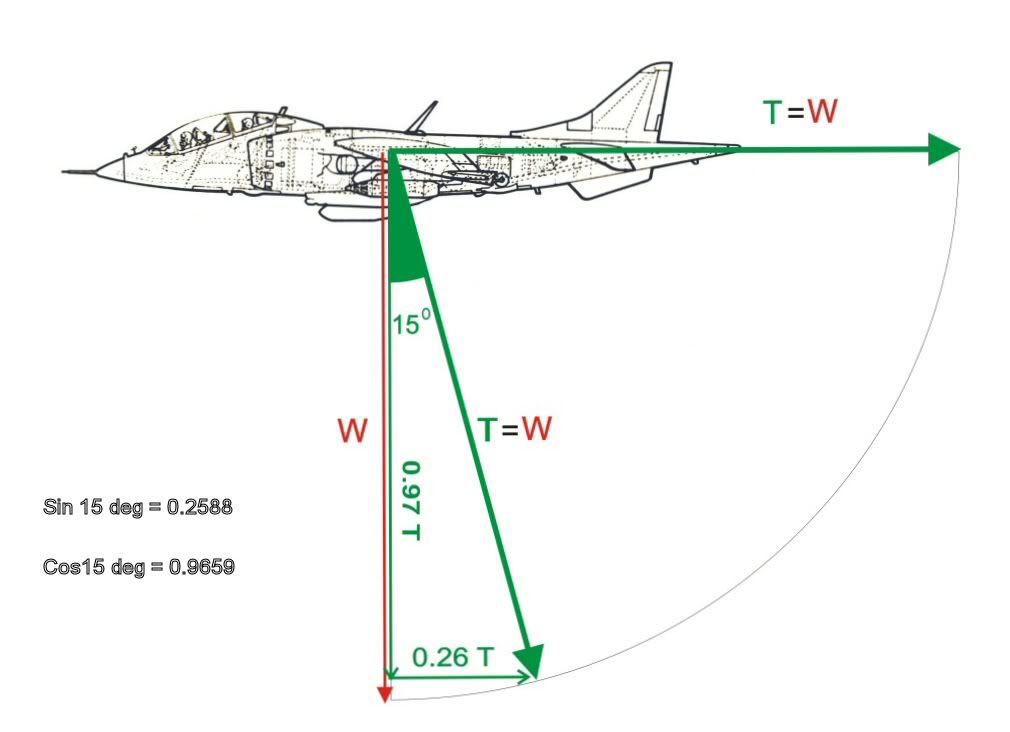
As IAS increases the wing provides an ever increasing lift (as with any other wing) helped by the fact that it has an angle of attack of some 8 deg with the aircraft in the hover attitude. The hover pitch attitude is determined by the undercarriage and the need to land mainwheels first to avoid overstressing the nose leg.
The above diag shows how trig works in the pilot's favour when stepping off from the hover. The first 15deg of nozzle rotation produces a .26g accel while only costing some .03g downwards. Something for (nearly) nothing!
The pilot rotates the nozzles at a rate that gives him his chosen accel path - too fast and a sink will occur - too slow and height will be gained. With a level transition the nozzles will be aft after about 13sec.
All extremely easy to do.
As you suggest jet engines are very much Sir Isaac in action.
With the Harrier in the hover the thrust and hence Sir Isaac are supporting 100% of the weight.
As the nozzles are rotated aft the vertical component of thrust reduces as the sine of the angle.
As IAS increases the wing provides an ever increasing lift (as with any other wing) helped by the fact that it has an angle of attack of some 8 deg with the aircraft in the hover attitude. The hover pitch attitude is determined by the undercarriage and the need to land mainwheels first to avoid overstressing the nose leg.
The above diag shows how trig works in the pilot's favour when stepping off from the hover. The first 15deg of nozzle rotation produces a .26g accel while only costing some .03g downwards. Something for (nearly) nothing!
The pilot rotates the nozzles at a rate that gives him his chosen accel path - too fast and a sink will occur - too slow and height will be gained. With a level transition the nozzles will be aft after about 13sec.
All extremely easy to do.
Last edited by John Farley; 15th Nov 2012 at 18:24.
Join Date: Dec 2007
Location: Pasadena
Posts: 633
Likes: 0
Received 0 Likes
on
0 Posts
Lyman, sir.
`Newton' and `Bernouilli' are both right in their way. `Newton' is couched in terms of conservation of momentum, `Bernouilli' in terms of conservation of energy. Both need to hold.
On a hovering Harrier, where does the lifting thrust act? Outwards and upwards equally at the elbow in the nozzles, where Mr Newton's second legal adviser would recommend his engineers to toughen the structure. The fuselage structure is on the rack, with seven tons pulling up, and seven tons pulling the machine apart abeam. As it starts to move forward, the flow over the wings takes some of the upward load, and the nozzles swivel back, rotating those 45 degree forces at the elbows forward, pulling the Harrier along instead of holding it up, while still trying to rip it apart acrossways.
Owain,
I fully accept your point that linear shear is not rotation, but once you account for the descending slab of air behind the aircraft, with the wingtip vortices to connect it to the non-descending air far from the flightpath, it's not a big stretch.
Close to the wing, I agree that the air that moving downwards the fastest is descending round the flap edge in that 757 picture, but that high-speed flow is part of a tight vortex - it spreads and slows behind, making the large scale dipole flow from the C17 wake picture, also effectively seen in the 747 contrail shot.
If the wing was all the way across a smooth windtunnel section, with no tips, the air behind the wing would have a uniform descending velocity component - there would be lift - and yet no rotation. I suspect almost the same is true for a sailplane wing - the downstream airflow is almost all descending slab, and almost no wingtip vortex.