


Theory on lift

Join Date: Jun 2011
Location: france
Posts: 760
Likes: 0
Received 0 Likes
on
0 Posts
@Machinbird,
Thank you for this link opening our mind, increasing the quality of the common vocabulary, and pulling us far from fear from new ideas, would they seem iconoclastic at the first glance.
That is Gentry's philosphy too.
Interdisciplinary discussion in that not academic forum is a step forward to fly better. John Tullamarine understands that very well.
Thanks to all.
rh
Last edited by roulishollandais; 1st Dec 2012 at 19:03.

Join Date: Jul 2009
Location: France - mostly
Age: 84
Posts: 1,682
Likes: 0
Received 0 Likes
on
0 Posts
ground effect works best on a wing of low aspect ratio

that ground effect works best on a wing of low aspect ratio. My takeaway is that
it is because the extended chord line makes a more concentrated area of
"capture"; there is less loss of compressive force, since the wing is not
skinny, but traps more air, for a longer time.
it is because the extended chord line makes a more concentrated area of
"capture"; there is less loss of compressive force, since the wing is not
skinny, but traps more air, for a longer time.
Low aspect ratio results in greater downwash, due to increased vortex strength. How on earth does a wing "trap" air????????
I think it's time to avoid further comments here in case some ill-informed moderator bans me!
Join Date: Aug 2011
Location: Grassy Valley
Posts: 2,074
Likes: 0
Received 0 Likes
on
0 Posts
'Low aspect ratio results in greater downwash, due to increased vortex strength. How on earth does a wing "trap" air????????'
You confuse 'trap' with your mistaken conclusion re its definition. (in my opinion)
You are likely concluding: "trap and hold". To sequester airflow means to enclose, or to restrict it; there is no rate described. Ram Air is fhe very definition of sequester, or 'restrict'.
I cannot speak for you, but my impression is that you reject any latitude in nomenclature, not helpful, imo.
Perhaps an example will help me. If an instantaneous image of airflow could be shown that demonstrates the zones of pressure the flow inhabits, one could say that for that instant, each "zone" shows 'trapped' air. Of course the flow is transient, or it would not be 'flow'. But without the ability to shepherd airflow, there would be no lift.
Is there a word you can suggest that describes these zones of pressure better than trapped? Screw trap, call it ________ . (contain) ?
Nothing can be compressed without somehow 'trapping' it. imho.
Last edited by Lyman; 1st Dec 2012 at 21:03.
Join Date: Jul 2009
Location: France - mostly
Age: 84
Posts: 1,682
Likes: 0
Received 0 Likes
on
0 Posts
Originally Posted by Jeff Scott
What happens in reality is that the ground partially blocks the trailing vortices and decreases the amount of downwash generated by the wing. This reduction in downwash increases the effective angle of attack of the wing so that it creates more lift and less drag than it would otherwise. This phenomenon is what we call ground effect ...
Last edited by HazelNuts39; 1st Dec 2012 at 21:15. Reason: clarification
Join Date: Aug 2011
Location: Grassy Valley
Posts: 2,074
Likes: 0
Received 0 Likes
on
0 Posts
Hi HazelNuts39...
Yours,
"The pressure distribution around the wing is the same as it would have out of ground effect at a somewhat greater angle of attack."
Are these relative distributions reflective of the arrested trail? Would the clipped vortices not reflect a change in the global distribution?
Doesn't the 'effective increase in AoA' more or less demonstrate an increase in pressure under the wing, forward of center of lift? The RamAir effect alluded to in Machinbird's lonk to the ground effect description?
Thnks
Join Date: Jul 2009
Location: France - mostly
Age: 84
Posts: 1,682
Likes: 0
Received 0 Likes
on
0 Posts
Originally Posted by Lyman
Doesn't the 'effective increase in AoA' more or less demonstrate an increase in pressure under the wing
Join Date: Aug 2011
Location: Grassy Valley
Posts: 2,074
Likes: 0
Received 0 Likes
on
0 Posts
The decrease in pressure causing the "additional lift"?
Is the underwing increase due the "Ram"? The overwing decrease due the foreshortened vortices?
The difference you describe shows the clipped vortices as having a greater effect on the GE than the Ram as described, yes? I agree.....
Are you in substantial agreement that the increased pressure underwing is partially due the effect of the four-sided "box" described by the two tip vortices, the underwing, and the asphalt?
Dare I include the downwash as a "bottom" to the "effective" "barrel"?
From which I would infer a "trap"?
Last edited by Lyman; 1st Dec 2012 at 22:34.
Join Date: Jul 2009
Location: France - mostly
Age: 84
Posts: 1,682
Likes: 0
Received 0 Likes
on
0 Posts
Lyman,
I would rather say that the changes in pressure are due to the increase of effective AoA, which in turn is the result of the reduced downwash induced by the vortex system, or rather by the superposition of the negative downwash induced by the virtual 'mirror image' of the vortex system.
I would rather say that the changes in pressure are due to the increase of effective AoA, which in turn is the result of the reduced downwash induced by the vortex system, or rather by the superposition of the negative downwash induced by the virtual 'mirror image' of the vortex system.
Last edited by HazelNuts39; 1st Dec 2012 at 22:16.
Join Date: Aug 2012
Location: on the beach
Posts: 359
Likes: 0
Received 0 Likes
on
0 Posts
Half a century ago I made a small surface skimmer and it had a non-aerofoil wing, simply flat under and top surfaces. I can vouch for it producing a lot of lift, the problem was that it produced too much. So no need for it to be an airfoil.
Join Date: Aug 2011
Location: Grassy Valley
Posts: 2,074
Likes: 0
Received 0 Likes
on
0 Posts
I like the mirrored silhouette. Alot. I picture it is a little "blurry" in outline, however, since it is composed of streamlines rather than Aluminum.
The incidence of the wing has not changed, hence, "effective". So to garner the benefit of AoA increase, "as if", we need to admit that the volume of airflow has increased beneath rhe wing, as it would had the leading edge raised.
Your preferred description works fine for me, my bent has to do with looking at things from different perspectives, anyway.
The "ram effect" doesn't need any further discussion, imo, except to say it is merely a part of the dynamic system, and should not be excluded in an objective setting?
Thks.
Join Date: Mar 2011
Location: engineer at large
Posts: 1,409
Likes: 0
Received 0 Likes
on
0 Posts
I have just looked at the aerospaceweb article on ground effects. Sorry, but I find little, in regards to ground effect, is based on reality as we understand it today.
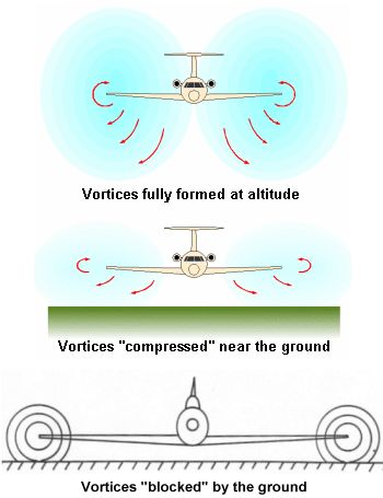
This diagram is completely incorrect for wake vortex generation, as is the explanation describing an aircraft on final. The wingtips do not generate a vortex. The vortex from an aircaft is a result of rollup, which does not occur at the tips, but inboard of the wing section and reliant on wing configuration and flap settings.

The rollup time and distance has many associated factors.
On final, the vortex creation is constantly changing with flap settings, speed and configuration. This is NOT currently explained by any model, especially CFD...why is that? If wing dynamics and principles of flight were understood
There are many issues that may seem simple, but have not been explained by models, or even attempts to model the differences. The effect on crosswinds, headwinds, tailwinds, centerwing, and flap settings.
We have all seen the typical diagram where the aircraft wake drops, then is blown sideways by the crosswind, and there are extensive calculations that try to model that advection rate.

Yet, this has been shown to be completely wrong by field measurements using LIDAR and SODAR.
The models make no attempt to add left/right wing configuration differences, crabbing, or other aircraft/met properties into account.

Notice how the standard equation is balanced....if not, the foundation of the calculations unwraps very quickly
Does that mean that the calculations are oversimplified, need to be generalized to model, or misunderstood?
This diagram is completely incorrect for wake vortex generation, as is the explanation describing an aircraft on final. The wingtips do not generate a vortex. The vortex from an aircaft is a result of rollup, which does not occur at the tips, but inboard of the wing section and reliant on wing configuration and flap settings.
The rollup time and distance has many associated factors.
On final, the vortex creation is constantly changing with flap settings, speed and configuration. This is NOT currently explained by any model, especially CFD...why is that? If wing dynamics and principles of flight were understood
There are many issues that may seem simple, but have not been explained by models, or even attempts to model the differences. The effect on crosswinds, headwinds, tailwinds, centerwing, and flap settings.
We have all seen the typical diagram where the aircraft wake drops, then is blown sideways by the crosswind, and there are extensive calculations that try to model that advection rate.
Yet, this has been shown to be completely wrong by field measurements using LIDAR and SODAR.
The models make no attempt to add left/right wing configuration differences, crabbing, or other aircraft/met properties into account.
Notice how the standard equation is balanced....if not, the foundation of the calculations unwraps very quickly
Does that mean that the calculations are oversimplified, need to be generalized to model, or misunderstood?
Last edited by FlightPathOBN; 2nd Dec 2012 at 17:35.
Join Date: Aug 2011
Location: Grassy Valley
Posts: 2,074
Likes: 0
Received 0 Likes
on
0 Posts
FP....
The center drawing showing "compressed" vortices gives one pause. RE: Ground Effect, a deflection of vortex means exactly what to 'lift'? The vortices may be on "rebound", but how do we conclude they are in "compression"?
As you say, the vortices are not "part" of the wing, but a relic, a "remnant" of lift?
Thank you sir.
Join Date: Jun 2011
Location: West of Offa's dyke
Age: 88
Posts: 476
Likes: 0
Received 0 Likes
on
0 Posts
Lyman
You may want to make a note of the date or something, but here is a first - I am going to agree with you!
NACA measurements (wind tunnel I'm afraid FlightpathOBN) made back in 1938 show that the build up of lift as you near the ground is NOT equivalent to an effective increase in AoA as suggested by the 'mirror image' modelling, but between say 5 and 10 deg AoA at least is more or less entirely due to a steady build up of pressure underneath the wing, with the upper surface flow changing very little from its free air behaviour. NACA TM 1095 if anyone is interested.
This of course says nothing about how wake vorticity is affected, but I didn't think that was the issue being debated here?
Last edited by Owain Glyndwr; 2nd Dec 2012 at 19:04.
Join Date: Aug 2011
Location: Grassy Valley
Posts: 2,074
Likes: 0
Received 0 Likes
on
0 Posts
Hallelujah....
The year of my birth no less. Yes, I think wake is not related here, many strings of discussion at once....
Can you comment on my proposition that the "box" effect of the bound vortices, plus downwash, under wing surface and ground (runway) partially explain the resultant "compression"?
Rgds.
The year of my birth no less. Yes, I think wake is not related here, many strings of discussion at once....
Can you comment on my proposition that the "box" effect of the bound vortices, plus downwash, under wing surface and ground (runway) partially explain the resultant "compression"?
Rgds.
Join Date: Jun 2011
Location: West of Offa's dyke
Age: 88
Posts: 476
Likes: 0
Received 0 Likes
on
0 Posts
Actually the tests were done in 1938 (editorial correction) but the report was issued in 1946.
Sounds reasonable. We know that in free air the greater the vertical distance below the wing TE the lower the downwash [because of the greater 'radius' from the wing bound vortex centre - sorry I couldn't resist saying that  ] so as the TE gets nearer the ground the more momentum the underwing flow has to shift to get by, so the bigger the force (pressure) it will need.
Different aspect of course, but wings fitted with endplates will need even more pressure build up because the air cannot escape sideways. This is limited though because there is no way the underwing pressure can build up beyond freestream total pressure.
Can you comment on my proposition that the "box" effect of the bound vortices, plus downwash, under wing surface and ground (runway) partially explain the resultant "compression"?
] so as the TE gets nearer the ground the more momentum the underwing flow has to shift to get by, so the bigger the force (pressure) it will need.Different aspect of course, but wings fitted with endplates will need even more pressure build up because the air cannot escape sideways. This is limited though because there is no way the underwing pressure can build up beyond freestream total pressure.
Last edited by Owain Glyndwr; 2nd Dec 2012 at 19:05.
Join Date: Aug 2011
Location: Grassy Valley
Posts: 2,074
Likes: 0
Received 0 Likes
on
0 Posts
Hi Owain...
"so as the TE gets nearer the ground the more momentum the underwing flow has to shift to get by, so the bigger the force (pressure) it will need."
Does the streamline contact the ground? It cannot, right? ("no matter can penetrate a streamline")
Does the streamline also "restrict" the passage of the underwing flow?
Join Date: Jun 2011
Location: West of Offa's dyke
Age: 88
Posts: 476
Likes: 0
Received 0 Likes
on
0 Posts
Does the streamline contact the ground? It cannot, right? ("no matter can penetrate a streamline")
Obviously the lower limit doesn't actually contact the ground.
The upper limiting streamline is the one that gets affected by the direction of flow off the upper surface, and it is this flow direction/velocity I suggested would vary with vertical position relative to the TE (in free air at least), but now I think about it I'm not so sure it works like that if the upper surface flow is unaffected by height changes. It may be that the downwash angle off the TE is unchanged but as height is reduced the relative areas of the stream tube at the LE and TE change so that the relative velocities change and that is all there is to it.
Does the streamline also "restrict" the passage of the underwing flow?
Being mischieveous, it is fairly easy to explain this increase in lift/higher underwing pressure using the dreaded Bernouilli, but at the moment I don't see how to explain it using Newton
 There must be a way though.
Join Date: Jul 2009
Location: France - mostly
Age: 84
Posts: 1,682
Likes: 0
Received 0 Likes
on
0 Posts
There must be a way though.
TM1095 compared to Jeff Scott curve:
Last edited by HazelNuts39; 3rd Dec 2012 at 11:07. Reason: graph added
Join Date: Aug 2011
Location: Grassy Valley
Posts: 2,074
Likes: 0
Received 0 Likes
on
0 Posts
I think it is to do with Newton, in this regard. Mass, as unperturbed air in front, is loath to move, "Remain at rest" (#1). Once entered the stream tube, it is loath to rest, 'momentum' (#2). Confronting the wing streamline, it must slow, "damming" the release of air through the aperture: wing, ground streamlines.
Hence the compression, increased pressure, and lift without benefit of incidence increase? (either AoA or incidence).
Hence the compression, increased pressure, and lift without benefit of incidence increase? (either AoA or incidence).