


AF447

Joined: Dec 2006
Posts: 1,350
Likes: 0
From: Florida and wherever my laptop is
It may not be ADIRUs that Failed
"Grunf, I think you are referring to the design criteria of a failure per 10^9 operational hours. You also mention probability. The probability of all three ADIRU's failing at once is more like 10^9*10^9*10^9!"
I know its late but I feel that I need to comment here. What may have failed is the software that runs the voting triplex not the actual ADIRUs themselves. It would be nice to think that software can be written that is 10^9 but its extremely unlikely. perhaps the spikes in speed and angle of attack looked like failed ADIRUs but were actually what was being experienced in extreme turbulence with way outside expectation 100Kt updrafts.
I know its late but I feel that I need to comment here. What may have failed is the software that runs the voting triplex not the actual ADIRUs themselves. It would be nice to think that software can be written that is 10^9 but its extremely unlikely. perhaps the spikes in speed and angle of attack looked like failed ADIRUs but were actually what was being experienced in extreme turbulence with way outside expectation 100Kt updrafts.

Joined: Mar 2002
Posts: 4,569
Likes: 1
From: Florida
ttcse
or alternately: the fuselage was slightly rolled and the fuselage stopped quicker than the galley when it hit the water
deSitter
the engines are unlikely to survive intact on their mounts in a spin (PA103, TWA800 etc.)
Assuming those triangular support members are on top of the gallery as it's installed in the aircraft, the bending and the puncture of roof of that gallery section seems to say either:
x) it was somewhat inverted when it struck the water (whether within the intact airframe, a part of the airframe, or by itself) or
x) it was somewhat inverted when it struck the water (whether within the intact airframe, a part of the airframe, or by itself) or
deSitter
In that case the large concentration of weight in the engines could provide a sort of gyroscopic stabilization to the spin.

Joined: Mar 2003
Aviation Qualifications: ATPL
Posts: 2,558
Likes: 155
From: BC
ACLS6;
Thanks for your trouble in finding the galley photos. I did have these two galley photos in doing my own searching and you're right, the first one is the rear galley; the second one doesn't show enough to confirm it's position. The quoted note in takata's post is very helpful however, so we know that the recovered galley section almost certainly came from the front of the aircraft as Been Accounting has said.
Takata's quoted post (from !!!!!!!!!!!!!!) if very helpful as it confirms what I had earlier posted regarding the defibrilator case - the orange case in photographs posted earlier is likely the Doctors Kit then.
ttcse;
Yes, correct of course, my mistake, (that's my own hindsight bias going from memory. We have to be so careful). The trolleys are stored in the larger section which is the open area without the bottom in this recovered section. The supports are on the top and I have confirmed this in the AMM.
captainflame;
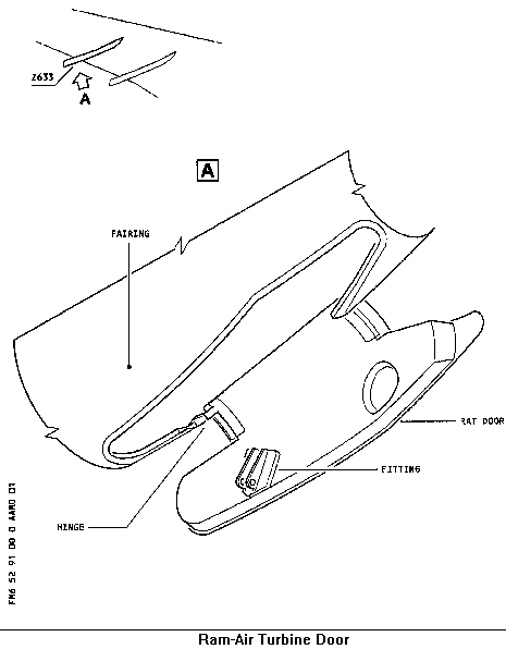
I thought so too and this drawing from the AMM seems to confirm the shape of the "black line" which we are assuming is the RAT door and not just a manufacturing join in one of the canoes. The RAT is stored in the #4 flap-track canoe on the right wing. Still, I think the photo is vague enough that we cant be sure:
Though AF may be different there are typically only two locations where dual seating arrangements are installed - at the rear galley on both port and starboard sides at R4 and L4, facing forward, (possibly making the seats recovered the starboard set), and forward at L1 (port side) at the main entry just behind the cockpit:
Machaca, ELAC;
Machaca, thanks for your comments - On which flight control we are seeing in the collected wreckage, the elevator, aileron and flap surfaces have been suggested. Both size, (about a meter in width) and the two slots on the right side of the photo may make the most likely control the inboard aileron. As you point out, the 'D' leading edge structure behind the slat is perhaps a bit small for a wing leading edge.
In the AMM I've examined the attach points for the flaps and these attach points are on the bottom leading edge of both inboard and outboard flaps which are then attached to the flap linkage on the flap track itself. I cannot say for sure but there does not appear to be a slot through which the flap and rod attach lug protrudes. Also, with the aileron, there are two distinct slots, and although there is damage in the referenced area in the photo, there appears to be the beginnings of a slot on the right-hand side.
All speculative of course but with data in hand:

and,
whereas the slots in the visible structure recovered suggest an aileron structure.

What appears to be one end of the structure can be seen neaer the end of the oxygen bottle in this photograph thus, given the location of the slots, this may suggest an aileron from the right wing:

Thanks for your trouble in finding the galley photos. I did have these two galley photos in doing my own searching and you're right, the first one is the rear galley; the second one doesn't show enough to confirm it's position. The quoted note in takata's post is very helpful however, so we know that the recovered galley section almost certainly came from the front of the aircraft as Been Accounting has said.
Takata's quoted post (from !!!!!!!!!!!!!!) if very helpful as it confirms what I had earlier posted regarding the defibrilator case - the orange case in photographs posted earlier is likely the Doctors Kit then.
ttcse;
In the recovered gallery section, photo page 92, I assumed the storage bins for metal bins were on the lower part. Now it seems that section would be on top as installed in the aircraft. And then those bent support tabs are attached somewhere near the ceiling. That makes much more sense.
captainflame;
Looks like the RAT door to me.
Though AF may be different there are typically only two locations where dual seating arrangements are installed - at the rear galley on both port and starboard sides at R4 and L4, facing forward, (possibly making the seats recovered the starboard set), and forward at L1 (port side) at the main entry just behind the cockpit:
Machaca, ELAC;
Machaca, thanks for your comments - On which flight control we are seeing in the collected wreckage, the elevator, aileron and flap surfaces have been suggested. Both size, (about a meter in width) and the two slots on the right side of the photo may make the most likely control the inboard aileron. As you point out, the 'D' leading edge structure behind the slat is perhaps a bit small for a wing leading edge.
In the AMM I've examined the attach points for the flaps and these attach points are on the bottom leading edge of both inboard and outboard flaps which are then attached to the flap linkage on the flap track itself. I cannot say for sure but there does not appear to be a slot through which the flap and rod attach lug protrudes. Also, with the aileron, there are two distinct slots, and although there is damage in the referenced area in the photo, there appears to be the beginnings of a slot on the right-hand side.
All speculative of course but with data in hand:
and,
whereas the slots in the visible structure recovered suggest an aileron structure.
What appears to be one end of the structure can be seen neaer the end of the oxygen bottle in this photograph thus, given the location of the slots, this may suggest an aileron from the right wing:
Last edited by PJ2; 20th June 2009 at 19:55.
Joined: Jun 2001
Posts: 286
Likes: 0
From: East of the Sun & West of the Moon
I disagree, as leading edge is of much greater arc and joins to front of wing box. Seeing as the remnant in question appeared to have a complete airfoil (not a Nike like swoosh of the slats), this is much more likely a trailing edge flap. Perhaps it and the canoe were proximal to the recovered spoiler?
Flaps do have rods and notches - they are difficult to see even when fully extended.
Flaps do have rods and notches - they are difficult to see even when fully extended.
I did in fact consider it as being a portion of the flaps initially. What made me reject that identification was the location of the notch for the actuator rod which, as your 3rd photo shows is below the leading edge of the flap, not at it as is seen in the recovered piece. Another consideration was that the flap actuator rod attachment point extrudes significantly and what is visible from the photo I saw (your second one) didn't match that.
Thanks for the first photo. This is one I hadn't seen. My thinking was that the segment was the portion of leading edge underlying the outermost slat from the forward spar forwards. At that point the section is quite a bit narrower than the slat makes the whole wing appear. But, looking at it from this other angle I'm no longer sold on that identification. Perhaps it is the aileron with a notch I've not seen during walk-arounds. If my perception of taper in this other picture is correct I think it would be too small overall to be a segment of the flaps.
Cheers,
ELAC
Joined: Aug 2002
Posts: 505
Likes: 0
From: London
Regarding search time for boxes in previous accidents, the New York Times (for what that may be worth) says today that in the case of the South African 747 one box was found no less than 14 months after the crash, while in the Adam Air 737 case they were found after 6 months.

Joined: Jun 2004
Posts: 5
Likes: 0
From: USA
Rarely post
All,
We are now talking about flat spins in chimpmunks, (sic), Pitts, etc. What a concept and I truly believe this has absolutely no bearing on this accident investigation. Why not go to inverted flat spins and carry this out to an additional ridiculous tangent? Spin/flat spin/inverted flat spin in an A330?
There are many posts on this thread. Some good and some bad. Many are intriguing and cause thought and research. It is extremely hard for me to believe that the aircraft broke up inflight unless it suffered the loss of a primary flight control or flight control supporting structure. If the VS did leave the airframe due to ultimate load limit being exceded, then other factors must have been contributing. If the crew in this tragedy experienced an overspeed past MMO/VMO, or slowed intentionally or unintentionally to below buffet boundry 1.5/1.3 this could be a contributing cause.
228 people lost their lives and this is not about conspiricy, national pride, Boeing vs Airbus or any other insignificant arguement. The investigation will determine the cause and hopefully direct the modification and or re-design of operational parameters for the airframe. This has been sucessfully accomplished after the accidents of most, if not all modern aircraft.
Over

Joined: Jun 2009
Posts: 1,344
Likes: 80
From: Bedford, UK
common mode failures
"Grunf, I think you are referring to the design criteria of a failure per 10^9 operational hours. You also mention probability. The probability of all three ADIRU's failing at once is more like 10^9*10^9*10^9!"
in the analysis of failure probability for redundant systems the concept of common mode failure is used (in the nuclear industry at least) to invalidate the chaining of probabilities such as suggested here. This recognises that anaysis is based on a 'model' of reality, not reality itself. I gather reading this forum that such failures have been observed rarely but often enough that 1 in 10^9 itself seems 'optimistic'.
Incidentally, one common mode failure path could be disruption through excessive vibration, I seem to remember reading that another version of similar equipment (different make) had problems in this respect before (hitting a mounting shelf ?) for which the existence of ISIS was a mitigating factor.
With all the systems which rely on inertial sensors, I would think that it is not possible to reset these in conditions where the aircraft is experiencing angular or linear accelerations above quite small limits owing to the need to find the direction of true 'g'.
Joined: Nov 2006
Posts: 896
Likes: 2
From: SoCalif
tquehl
".. ridiculous tangent? Spin/flat spin/inverted flat spin in an A330? ...
I would humbly suggest everyone take their training/experience/prejudice on the topic to Techlog if you don't like reading it here.
GB
I would humbly suggest everyone take their training/experience/prejudice on the topic to Techlog if you don't like reading it here.
GB

Joined: Mar 2003
Aviation Qualifications: ATPL
Posts: 2,558
Likes: 155
From: BC
tquehl;
Yes, I know.
I have been wrestling with experience vice engineering data - the airplane is extremely strong; is the center of a fully-developed ITCZ CuNim cell capable of breaking an airplane? I think it is fully capable of overstressing the structure to the breaking point regardless of what the crew does with the airplane but I am not an engineer so cannot show or discuss the forces involved.
The available evidence (photos of the wreckage collected thus far) indicates that very large sections of the interior cabin structure were ejected/broke loose and were not deformed by collision with or otherwise inhibited in their trajectories by the fuselage structure. That means either very large sections of fuselage were missing in an otherwise somewhat-intact main structure (like the BOAC B707 over Fuji), or a more complete in-flight failure of all major structures.
The alternative of a low-speed ditching has been suggested but if we think about that, that means the aircraft would have had to have been under control until that point - we could expect at least further ACARS messages in such circumstances (assuming electrical power available and the pitot/ADIRU issues resolved somehow - very doubtful but possible).
The alternative of a "flat" spin suggesting a "pancake" impact has also been made, (the theory which has suggested that that is how the VS broke loose - upon impact, "tilting back" and fracturing the rudder structure - I submit that the tail-structure in that area is far more frangible and would do little to no damage to a vertical structure striking it from the top), but such an impact would result in very high 'g' loading so one would expect far more deformation of the larger parts seen in the photographs than is evident.
There is a common aspect to everything seen in the photographs; the structures are all relatively light in comparison to wings/engines/horizontal stabs/landing gear. Perhaps, like Challenger, (and as has been suggested here by various posters before), these lighter parts fell out of the main, heavier structures which had already failed into a number of open sections and continued to fall for many minutes with a comparatively, (and obviously) benign water-impact.
It has also been suggested that the ACARS trace occurred during the initial accident sequence and perhaps bears no relationship to the Air Caraibe incident - again, we must be cautious of hindsight bias while remaining open to the possibility of the more likely events.
I don't know what part of this is my own hindsight bias and which part is reasonable, so criticism of these kinds of notions is most important.
PJ2
It is extremely hard for me to believe that the aircraft broke up inflight
I have been wrestling with experience vice engineering data - the airplane is extremely strong; is the center of a fully-developed ITCZ CuNim cell capable of breaking an airplane? I think it is fully capable of overstressing the structure to the breaking point regardless of what the crew does with the airplane but I am not an engineer so cannot show or discuss the forces involved.
The available evidence (photos of the wreckage collected thus far) indicates that very large sections of the interior cabin structure were ejected/broke loose and were not deformed by collision with or otherwise inhibited in their trajectories by the fuselage structure. That means either very large sections of fuselage were missing in an otherwise somewhat-intact main structure (like the BOAC B707 over Fuji), or a more complete in-flight failure of all major structures.
The alternative of a low-speed ditching has been suggested but if we think about that, that means the aircraft would have had to have been under control until that point - we could expect at least further ACARS messages in such circumstances (assuming electrical power available and the pitot/ADIRU issues resolved somehow - very doubtful but possible).
The alternative of a "flat" spin suggesting a "pancake" impact has also been made, (the theory which has suggested that that is how the VS broke loose - upon impact, "tilting back" and fracturing the rudder structure - I submit that the tail-structure in that area is far more frangible and would do little to no damage to a vertical structure striking it from the top), but such an impact would result in very high 'g' loading so one would expect far more deformation of the larger parts seen in the photographs than is evident.
There is a common aspect to everything seen in the photographs; the structures are all relatively light in comparison to wings/engines/horizontal stabs/landing gear. Perhaps, like Challenger, (and as has been suggested here by various posters before), these lighter parts fell out of the main, heavier structures which had already failed into a number of open sections and continued to fall for many minutes with a comparatively, (and obviously) benign water-impact.
It has also been suggested that the ACARS trace occurred during the initial accident sequence and perhaps bears no relationship to the Air Caraibe incident - again, we must be cautious of hindsight bias while remaining open to the possibility of the more likely events.
I don't know what part of this is my own hindsight bias and which part is reasonable, so criticism of these kinds of notions is most important.
PJ2
Last edited by PJ2; 20th June 2009 at 20:53.
Joined: Jan 2008
Posts: 349
Likes: 0
From: Atlanta, GA, USA
elevator
Thanks PJ2,
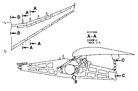
On the structure we see an actuator fitting within its recess, and then immediately to the right of it, half the remaining recess with a hinge fitting (failure occurred at the recess itself), then open structure. According to the elevator diagram posted, there are two such adjacent actuator/hinge fittings on each elevator. That, and its size, would seem to indicate that the structure is part of the elevator.
-drl
Joined: Jun 2009
Posts: 56
Likes: 0
From: Midpines, CA
Very good points PJ2.
Another way of looking at this is from the standpoint of what has not been found. (I know, a lot!)
Engines, not something that will float up, same with CVR, FDR.
But we have also not see obvious cockpit pieces, tail structure other than VS, major wing structure other than slats or spoilers that appear to have been ripped loose.
Also we seem to have a cluster of debris from the forward galley area, but not necessarily other cabin debris in quantity.
I also remember some early descriptions of bodies that sounded like they were for the most part intact, and the later descriptions or almost unidentifiable remains. If the bodies are identified their seating location combined with their condition may prove to be very valuable information.
About all I have been able to conclude is that if I am ever on an A/C in distress I will hold on to the lav door, clutch the defibrillator case, and try to post a msg here as to what happened so you all don't have to wonder
Joined: Mar 2003
Aviation Qualifications: ATPL
Posts: 2,558
Likes: 155
From: BC
deSitter;
Except the attach points on the elevator are more evenly-spaced, while the aileron attach points are close together.
I can't judge the size because I don't know how large the elevator is compared to the aileron, at that point in either structure. An oxygen bottle is about a meter long and that's about how wide the flight control we're examining is.
I don't think it's flap, (because of the two attach points) but further photos are needed before we can determine origin.
I think it is important (especially with so little real evidence) because one outcome is "wing" and the other is "tail feathers".
regards,
PJ2
That, and its size, would seem to indicate that the structure is part of the elevator.
I can't judge the size because I don't know how large the elevator is compared to the aileron, at that point in either structure. An oxygen bottle is about a meter long and that's about how wide the flight control we're examining is.
I don't think it's flap, (because of the two attach points) but further photos are needed before we can determine origin.
I think it is important (especially with so little real evidence) because one outcome is "wing" and the other is "tail feathers".
regards,
PJ2
Joined: Jul 2005
Posts: 99
Likes: 0
From: LFBO
#2024 PJ2
This galley is forward of Door 2 and opens towards the rear of the aircraft
The photo in #2025 is the rear galley aft of door 4
Can you say whether the galley faces, (bins and trollies), aft or forward?
The photo in #2025 is the rear galley aft of door 4
Joined: Jun 2009
Posts: 801
Likes: 74
From: Germany
I�m following the various discussions with great interest.
Concerning the original location of the recovered items of the cabin i suggest it would be very helpful to use a seatplan.
Maybe it�s possible to continously edit the picture by posters with coresponding airctaft knowledge.
Hope the link works!
http://i.slimg.com/seatguru/airlines...irbus_A330.gif

Concerning the original location of the recovered items of the cabin i suggest it would be very helpful to use a seatplan.
Maybe it�s possible to continously edit the picture by posters with coresponding airctaft knowledge.
Hope the link works!
http://i.slimg.com/seatguru/airlines...irbus_A330.gif
Joined: Jan 2008
Posts: 349
Likes: 0
From: Atlanta, GA, USA
attach points
In your linked diagram, those appear to be hinge points on the outboard side of the outboard aileron. The actuators are on the inboard (wide) side, see the planview photo here:
Airbus A330 - Wikipedia, the free encyclopedia
http://upload.wikimedia.org/wikipedi...5b-dbs_arp.jpg
They are also external to the structure and reside in aerodynamic nacelles, because one needs a greater moment arm from the actuator than with the elevator, I would imagine.
Barnyard math based on this photo yields a length for the outboard aileron of 16 ft (~5m) while the elevator is about 30 ft (~10m) - this does tend to indicate the aileron but I don't know how much structure is missing in the debris.
The photo mentioned shows what a magnificently beautiful airplane this beast is - sigh
-drl
Joined: Apr 2009
Posts: 330
Likes: 0
From: Petaluma
Please note the lack of camber on the piece in the photograph. Elevator needs no 'airfoil', it's work is done by deflecting airflow, as a trim tab would, and 'lift' isn't part of the purpose. It works on both sides of its companion, as the Rudder does with the VS, 'lift' ("airfoil" would inhibit one side, useless for what it needs to do). I will admit scale and perspective are difficult with these photos, but the unit appears to be symmetrical in cross section.
I'll repeat, as I see it, it is the outer and underside tip of the port elevator.
rgds all
Will
I'll repeat, as I see it, it is the outer and underside tip of the port elevator.
rgds all
Will
Last edited by Will Fraser; 20th June 2009 at 22:07.