


Continental Engine AD - Big Troubles?


Joined: Aug 2005
Aviation Qualifications: PPL
Posts: 612
Likes: 387
From: EDLB
Yes but if this makes a SEP quit in the first 200h then there is something serious wrong with the construction or the mechanic education. My view is that the construction is flawed and they kicked for 50 years the can down the road, The SP is from 1999 and described the same problem as they have now.


Joined: Oct 2006
Aviation Qualifications: A&P
Posts: 1,354
Likes: 273
From: USA
FWIW: its more than just a single mechanic failure as there is a QA system that failed also. So it will be interesting to see if the forthcoming SB will explain what happened.
That said, all rings/clips have a sharp side and a round side. However, some have an additional 10 deg bevel on the round side and fall under different specifications and part numbers. The beveled rings need a corresponding beveled/chamfered groove to be installed hence the specific direction. In general, non-beveled rings/clips have no specific install orientation as the grooves are uniform. But all are still considered standard parts.
Regardless, if the ring was beveled and installed backwards then it would have also failed the minimum ear gap check of .179 “ as well. So not one but 2 failures in the system. And with 50+ years of no ring/clip failures its not a design issue but unfortunately a human issue.
FYI: the SB 99-3 I linked above has zero to do with this issue. The SB corrected a bushing install problem not a ring problem which was causing cracks in the crank. I used it strictly because it had pics of the same area.

Joined: Oct 2006
Aviation Qualifications: A&P
Posts: 1,354
Likes: 273
From: USA
MSB 23-01, Crankshaft Counterweights has been released.


Joined: Oct 2019
Aviation Qualifications: Non-Aircrew
Posts: 1,706
Likes: 1,085
From: USA
Really confused - is the snap ring groove really not uniform in depth all the way around? Also, is there a line that should not be there? The pin should also block the view of the far side of the counterweight in the gap.

Joined: Oct 2006
Aviation Qualifications: A&P
Posts: 1,354
Likes: 273
From: USA
I believe the line you refer to is part of the weight itself as shown in SB picture. The pin is not that wide.
Joined: Oct 2019
Aviation Qualifications: Non-Aircrew
Posts: 1,706
Likes: 1,085
From: USA
I have never seen an offset depth in any snap ring application guide for any type of snap ring. Even if one did, the ring isn't guaranteed to be locked into position so any offset preference could be disaster.
That part of the weight is slot. That horizontal line segment should bridge where the two horizontal segments are separated above the pin. I know the pin isn't that wide; that's why I think it's wrong.
In vertical order there are are two large top flats, two smaller slot flats, the top edge of the bushing bore, which is below the two smaller slot flats, and then the top edge of the pin.
Because of the slot, there is not a complete bore where the bushings are set, so there is no horizon line in that gap.
I looked at the old notice - the slot goes all the way through - there should not be material sectioned in the middle. This matches the hidden lines in the overall face view.
Perhaps they need to hire someone with drafting experience.
Joined: Oct 2006
Aviation Qualifications: A&P
Posts: 1,354
Likes: 273
From: USA
https://www.rotorclip.com/cat_pdfs/vho.pdf
Perhaps they need to hire someone with drafting experience.
Joined: Oct 2019
Aviation Qualifications: Non-Aircrew
Posts: 1,706
Likes: 1,085
From: USA
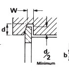
Here's what I think it should look like -

Seems like large (any) errors in maintenance diagrams should be a huge concern.
Notice in that snap ring dimension chart that depth is uniform even though the ring section isn't.
Example the -165 has a bore diameter of 1.653, a ring groove diameter of 1.773, and a depth of .060 = (1.773-1.653)/2
Seems like large (any) errors in maintenance diagrams should be a huge concern.
Notice in that snap ring dimension chart that depth is uniform even though the ring section isn't.
Example the -165 has a bore diameter of 1.653, a ring groove diameter of 1.773, and a depth of .060 = (1.773-1.653)/2
Joined: Apr 2009
Aviation Qualifications: Non-Aircrew
Posts: 1,601
Likes: 704
From: DM33
I’ve been rebuilding engines (mainly air cooled motorcycle types) since the early 1970s and have always been aware that the side of a circlip with the sharp edge should be the thrust bearing side. They don’t come with instructions! A good example is those holding gudgeon (wrist) pins in pistons. The last thing you need is a loose clip and the end of the pin scraping the bore. The rounded edge of the circlip can ride up the (square edged) groove and pop out the same way it was incorrectly put in. Wire circlips are different in that they have rounded grooves.
The following steps outline the process for installing internal circlips:
- Begin by choosing a pair of internal circlip pliers which fit into the circlip end holes
- You should then fit the plier tips into the holes on the ends of the retaining ring to be installed
- Squeeze the handles to close the circlip plier handles and contract the circlip to the desired size
- Guide the ring into the circlip groove and release the pliers
ref - https://uk.rs-online.com/web/content...circlips-guide
Not clear to me if there is agreement here or disagreement. I've worked on a few motor cycle engines (mostly BSA 650) and a few car engines and gear boxes. I don't think I ever paid any attention to circlip facing direction but I always ensured they were fully seated.
The TCM mandatory service bulletin does not require removal of circlips to check face orientation. It only requires a check for seating and angular orientation. They don't seem to think face orientation is important.
Joined: Oct 2006
Aviation Qualifications: A&P
Posts: 1,354
Likes: 273
From: USA
Once installed the ring ear gap measurement comes into to play and the face position is moot at that point. The "sharp" face is simply a means to tactilely determine which ring face is which prior to install. My guess is if the ring was not facing the proper way it will fail the gap test which does require removal and replacement of the ring per the SB.
Joined: Apr 2009
Aviation Qualifications: Non-Aircrew
Posts: 1,601
Likes: 704
From: DM33
Joined: Oct 2019
Aviation Qualifications: Non-Aircrew
Posts: 1,706
Likes: 1,085
From: USA
I have never seen a tapered groove for a snap ring. I have seen semi-circular grooves for formed wire retainers.
The main problem that appears to be this case is if the person installing the ring thinks that just because they have pushed the ring into full flat contact with the item being retained that the ring must be in the groove. Given the spring load the ring will be wedged into the bore and appear to be secure, but if one doesn't look to see then this situation can certainly occur.
The main problem that appears to be this case is if the person installing the ring thinks that just because they have pushed the ring into full flat contact with the item being retained that the ring must be in the groove. Given the spring load the ring will be wedged into the bore and appear to be secure, but if one doesn't look to see then this situation can certainly occur.
Joined: Apr 2009
Aviation Qualifications: Non-Aircrew
Posts: 1,601
Likes: 704
From: DM33
The main problem that appears to be this case is if the person installing the ring thinks that just because they have pushed the ring into full flat contact with the item being retained that the ring must be in the groove. Given the spring load the ring will be wedged into the bore and appear to be secure, but if one doesn't look to see then this situation can certainly occur.
Joined: Oct 2006
Aviation Qualifications: A&P
Posts: 1,354
Likes: 273
From: USA
They're not common, but there are beveled snap ring applications out there. As I recall they were used mainly where the retained part was submerged in oil, fuel, or other lubricants. I don't know if this specific installation uses them but if you have access to MIL-SPEC cross-reference tables for TCM parts we can put this topic to rest. TCM P/N: 62104 retaining ring. The applicable spec will be MS16625 internal ring, basic or MS16631 internal ring, beveled.
Don't know. As noted above if a beveled ring is used in this installation the groove will have a 15 deg taper to match the ring, i.e., the bottom of the groove will be narrower than the top. Just a guess as to why the ring didn't seat. Regardless, if the minimum ear gap wasn't checked by the installer doesn't matter what the groove profile is.
Joined: Oct 2006
Aviation Qualifications: A&P
Posts: 1,354
Likes: 273
From: USA
FAA AD has been issued.
AD 23-04-08
AD 23-04-08
Joined: Oct 2019
Aviation Qualifications: Non-Aircrew
Posts: 1,706
Likes: 1,085
From: USA
OK - Now I've seen one. Interesting. Google finds no cross reference to the TCM number.
I found the MS16631 document on quicksearch.dla.mil ; still Active.
INTENDED USE- TO PROVIDE SHOULDERS FOR POSITIONING AND RETAINING MACHINE COMPONENTS IN HOUSINGS.
TAPERED DESIGN PRINCIPLE PERMITS RINGS TO MAINTAIN PRACTICTICALLY (sic) CONSTANT CIRCULARITY. THE RINGS
WITH BEVEL ON OUTER CIRCUMFERENCE WHEN SPRUNG INTO GROOVE WITH TAPERED OUTER WALL
CORRESPONDING TO RING BEVEL WILL SELF ADJUST AND PROVIDE SECURE PRESSURE FIT AXIALLY TO TAKE UP END
PLAY. THE USE OF THE FOLLOWING FORMULAS ARE BASED ON THE FACT THAT THE RING MATERIAL WILL NOT FAIL IN
COMPRESSION
I think the instructions would mention a taper as 100% in the axial pressure application a backwards ring would not seat, while a regular ring can partially seat either way.
It would be nice to see that cross reference. I can understand why the engine company would "hide" an underlying number. The company I worked for did this with commercial parts; the cynical view is that we got to sell parts with some markup, but the practical side is our internal document also included the exact companies that the parts could be sourced from. Yeah, there were trust issues that limiting to certain vendors made manageable. Too many ways for counterfeit items to get into the supply chain.
It was also useful to see what the user (DoD) was up to - they start ordering a lot of some part and we know exactly what it goes into and try to figure out if something has gone wrong - usually a problem with maintainers (like this situation) but possibly some other design or manufacturing issue.
Edit: Looking closer, the smallest MS16631 is for a 1.00 inch ID, which is far larger than this application.
Last edited by MechEngr; 24th February 2023 at 00:37.
Joined: Oct 2006
Aviation Qualifications: A&P
Posts: 1,354
Likes: 273
From: USA
FYI: FAA has decided to supersede the original AD 2023-04-08 with AD 2023-05-16. The "new" AD adds several more engine models, clarifies the SFP requirement, adds a flow chart, and a few other minor changes. The AD will be published tomorrow but here is a final draft version: AD 2023-05-16
