


Continental Engine AD - Big Troubles?

Thread Starter

Joined: Jun 2020
Posts: 122
Likes: 33
From: Cold, wet and windy
Continental Engine AD - Big Troubles?
Hey again all, just been reading about Cirrus grounding their entire fleet until further notice due to an upcoming Continental AD. The part that got me was:
'Continental Aerospace Technologies is working with the FAA on possibly developing an Airworthiness Directive (AD) on aircraft powered by late models of several of its engine models. These include 360-, 470-, 520- and 550-series engines. Continental is urging owners of planes with any of these engines with a manufacturing date between June 1, 2021, and February 7, 2023, to voluntarily ground their planes “until further information is available.'
This is an enormous call, particularly as it will ground most aircraft with an engine less than 200 hours old. Keen to see what you all think.
Cheers, Mach1
Last edited by Mach1Muppet; 11th February 2023 at 02:43. Reason: poor grammar

Joined: Jun 2002
Aviation Qualifications: PPL
Posts: 7,177
Likes: 297
From: Nanaimo (CAC8)
just been reading about Cirrus grounding their entire fleet


Joined: Apr 2007
Posts: 20
Likes: 0
From: Nr. EGNT
Currently dates between June 1, 2021 to February 7, 2023 and with less than 200hrs on the engine. Also applies to OH engines with a new Crankshaft between said dates. The issue is centered around Crankshaft counterweight pins and the circlips that hold them.
looks like a two day mx input to pull a few cylinders and inspect.
Brought on by three in service engine failures (not Cirrus airframes). Cirrus were the first manufacturer to break cover and start to ground (or pause, as they called it) their own fleet that fell between the initial dates. The AD will probably give five hours grace to ferry with �essential crew� crew only to a mx shop for checks and rectification.
probably those caught up in this already know everything mentioned above. Took a while to tease the actual issue out of Continental.

Joined: Oct 1999
Posts: 1,444
Likes: 21
From: Beyond the black stump!
You might want to read this AD.
https://www.federalregister.gov/docu...with-a-certain
https://www.regulations.gov/docket/F...-0027/document
https://www.federalregister.gov/docu...with-a-certain
https://www.regulations.gov/docket/F...-0027/document

Joined: Jan 2008
Posts: 17,733
Likes: 2,114
From: Reading, UK
You might want to read this AD.
https://www.federalregister.gov/docu...with-a-certain
https://www.regulations.gov/docket/F...-0027/document
https://www.federalregister.gov/docu...with-a-certain
https://www.regulations.gov/docket/F...-0027/document
Joined: Oct 2006
Aviation Qualifications: A&P
Posts: 1,354
Likes: 273
From: USA
You might want to read this AD. https://www.federalregister.gov/docu...with-a-certain
Joined: Dec 2019
Posts: 786
Likes: 173
From: OnScreen
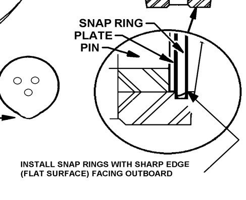
FYI: this is not the AD in question for the OP issue. There is no AD currently in the works but an SB in the works which will contain S/Ns. TCM came out with a notice yesterday. Word is supposedly the retaining rings/circlips for the crankshaft dampener bushings/pins were orientated opposite of the installation requirements. If you want to see the area in question look in the old SB 99-3 which addressed a different issue. Given they have it narrowed down to less than 200 hrs TIS engines they probably have a good idea of what is the cause. Regardless, my guess there more to this than a reversed circlip as most have no specific orientation requirements.
So, it could be, one specific mechanic did install the circlips consequently the wrong way around, and it seems to be known from experience, that the engine destroys itself within 200 TIS, when the circlip(s) is/are mounted wrongly.
Retrieve the engine serials this mechanic worked on, follow the delivery trail, and it is known which engines need to be opened up and potentially will need a crankshaft rebuild/revision. A complication can be, that crankshafts might be prebuilt/assembled, leaving the challenge, which crankshaft ended up in which engine. An issue is to reliable reach all aircraft owners/users with affected engines.
Joined: Oct 2006
Aviation Qualifications: A&P
Posts: 1,354
Likes: 273
From: USA
It does and is a result the stamping manufacture process. Common AN/NAS steel washers have the same feature. Supposedly the weight pin retainer plate is stamped also. One theory is the sharp side of the clip and the sharp side of the retainer plate may cause interference and prevent complete seating of the clip. However the clip ear dimension check should have caught that, if it was checked.
The groove dimension is spec to the clip thickness. Either way there should be no play unless not seated. Plus theres a note that the retainer plate should not have any play at the pin. Perhaps when the SB is released it will provide more on the reason.
Mount it the other way around, and it'll probably get some slack,
Joined: Jan 2008
Posts: 17,733
Likes: 2,114
From: Reading, UK
While they might possibly exist, I've never encountered a circlip that came with instructions regarding which way round it should face.
Presumably if they do, they would have to feature some unambiguous marking on one face, or have some other asymmetry so that the correct orientation could be guaranteed.
Sounds a tad unlikely to me.
Presumably if they do, they would have to feature some unambiguous marking on one face, or have some other asymmetry so that the correct orientation could be guaranteed.
Sounds a tad unlikely to me.
Joined: Oct 2006
Aviation Qualifications: A&P
Posts: 1,354
Likes: 273
From: USA

Joined: Dec 2019
Posts: 786
Likes: 173
From: OnScreen
Joined: Oct 2006
Aviation Qualifications: A&P
Posts: 1,354
Likes: 273
From: USA
We thought the same. But if that was the case then it should have been black below the "diagonal" line. However, it could have been mistaken by the person installing the clips?? The larger picture associated with this close up doesn't show that line. The full diagram is in the SB 99-3 link above.
Joined: Dec 2019
Posts: 786
Likes: 173
From: OnScreen
It does and is a result the stamping manufacture process. Common AN/NAS steel washers have the same feature. Supposedly the weight pin retainer plate is stamped also. One theory is the sharp side of the clip and the sharp side of the retainer plate may cause interference and prevent complete seating of the clip. However the clip ear dimension check should have caught that, if it was checked.
The important aspect in this is, the manufacturer documentation explicitly mentions the way the circlip needs to be mounted.
I think, the clip ear dimension check/spec is there to have an extra check, whether the circlip is mounted correctly. Though, a precise mechanic might have used "force" to enforce the proper clear ear size.
The no-play remark for the retainer pin suggests, the mounting of the circlip creates maybe a somewhat spring-loaded construction, to have the whole in the normal situation "without play". Another argument, to have the sharp edge of the circlip on the outside and being forced somewhat into the groove, together with the clip ear spec to check on this. Temperature effects to be seen, though.
The SB/AD would be an interesting one.
Joined: Oct 2006
Aviation Qualifications: A&P
Posts: 1,354
Likes: 273
From: USA
These clips are standard and cost about $0.70 USD each. Nothing special about them. The ring grooves and retainer plates are checked as part of overhaul with the bushings changed as well. Usually one buys a ring kit for OH and gets new circlips for this application.
Avoid imitations

Joined: Nov 2000
Aviation Qualifications: ATPL
Posts: 15,115
Likes: 1,091
From: Wandering the FIR and cyberspace often at highly unsociable times
While they might possibly exist, I've never encountered a circlip that came with instructions regarding which way round it should face.
Presumably if they do, they would have to feature some unambiguous marking on one face, or have some other asymmetry so that the correct orientation could be guaranteed.
Sounds a tad unlikely to me.
Presumably if they do, they would have to feature some unambiguous marking on one face, or have some other asymmetry so that the correct orientation could be guaranteed.
Sounds a tad unlikely to me.
Joined: Dec 2019
Posts: 786
Likes: 173
From: OnScreen
I�ve been rebuilding engines (mainly air cooled motorcycle types) since the early 1970s and have always been aware that the side of a circlip with the sharp edge should be the thrust bearing side. They don�t come with instructions! A good example is those holding gudgeon (wrist) pins in pistons. The last thing you need is a loose clip and the end of the pin scraping the bore. The rounded edge of the circlip can ride up the (square edged) groove and pop out the same way it was incorrectly put in. Wire circlips are different in that they have rounded grooves.


Joined: Nov 2010
Posts: 1,167
Likes: 180
From: USA
Just a pilot, fix a lot of things around the house. Having a clip that fits both ways, no obvious markings or instructions what the correct way is, and the engine blows up within 200 hours if you do it wrong sounds like an unacceptable risk.
Avoid imitations
Joined: Nov 2000
Aviation Qualifications: ATPL
Posts: 15,115
Likes: 1,091
From: Wandering the FIR and cyberspace often at highly unsociable times
Maybe it’s just that some less experienced engineers/mechanics these days (possibly a very small number) don’t have certain basic “nouse” about what’s right and what’s not.