


Litton INS - LTN-72RH

Thread Starter

Joined: Jan 2005
Posts: 68
Likes: 4
From: Munich/Gemany
Hi G4PoweredDecent, thanks for your answer! Always great to hear first-hand experience! Surely you had plenty of time playing with the systems during your time riding the DC10 ;-) Some questions after reading your cool post:
Hm, I guess in real life you never used more than a hand full of waypoints, even on longer flights, right? Before advent of digital means for exchanging route information it was probably to cumbersome to enter all these waypoints correctly using the numeric keypad?
Ups - so the pilot taking the aircraft over from you for the next flight was wondering how to navigate without a CDU to operate the INS? (Just joking  )
)
That is an interesting point - so there was no intervention with the INS necessary and the correction was entered automatically via the digital connection between the Radio nav and the INS or did you at least have to confirm a correction on the CDU before it got active?
Wow, that indeed would be auite nice. But I guess this value is from the navigation accuracy mixed from the three INS installed and maybe regular (1/h) radio updates?
Amazing! Meanwhile I got hands on the relevant pages of DC10 documentation for the wiring (that is what you probably refer to as Lam Schematics?) if the INS to the CDU and to each other. Are the manuals you mention the "Pilot's manuals" or do they contain more technical information (or even schematics?)? You can always reach out for me via private mail using erik -at- baigar -dot- de. Thanks for your efforts in replying here!
92 had 100 waypoints
I have both these units on my shelf and used both during my years flying the DC10
)
Radio updates from DME/DME would periodically bring about a course correction.
Usually less than about 0.3nm/hour of operation from what I can remember.
I still have the user manuals for both these units

Thread Starter
Joined: Jan 2005
Posts: 68
Likes: 4
From: Munich/Gemany
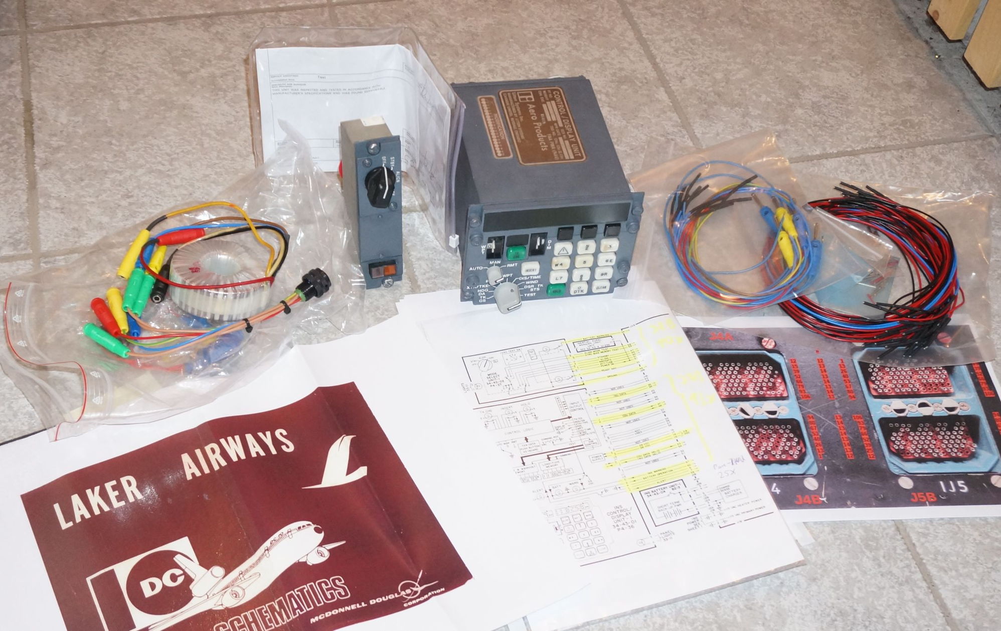
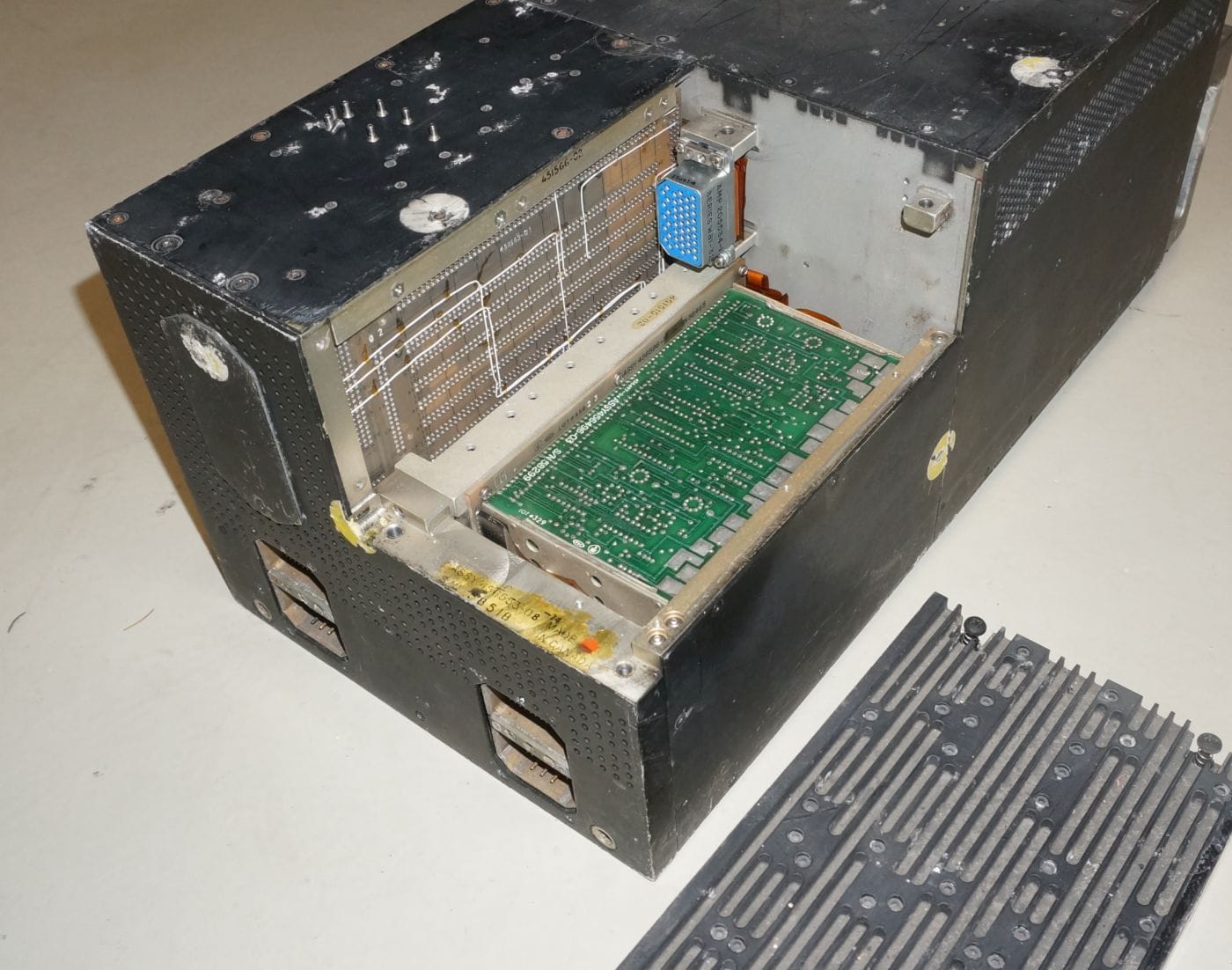
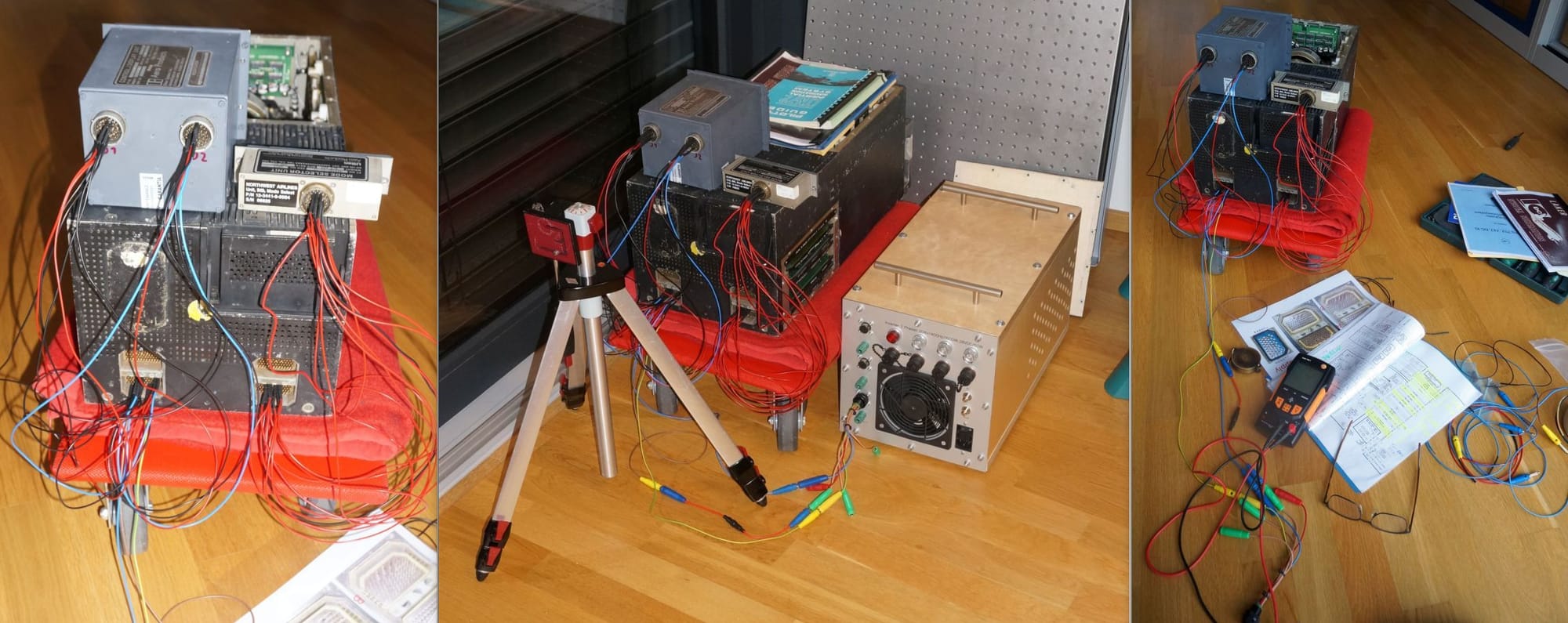
That here is my LTN72RH-Experimental kit: Once I will have access to the INS unit after Corona, I will use the documentation from the Laker Airways DC10s (bottom left), to wire up the INS to my 3 phase supply using a prepared transformer (left, top). The mode select and CDU panels (top row, middle) will be connected using cables prepared with the appropriate pins&sockets (top, right) and being plugged directly into the INS's rear ARINC404 plugs (numbered layout of these see bottom, right). Will be fun to see whether there still is life in my unit:

Joined: Sep 2003
Aviation Qualifications: ATPL
Posts: 955
Likes: 68
From: away from home
Looks quite like the Litton 51 CDU we had in most of our DC-8-63s. A couple had Omega (pure crap), and I flew one or two that had Carousel INS. Loading the first 9 waypoints was the F/Os job, sometimes (actually quite often) the crossload of waypoints to the Left unit (remote) would not work so it had to be done all over again on that unit...

Last edited by oceancrosser; 30th March 2021 at 11:56.
Joined: Jan 2023
Posts: 13
Likes: 0
From: Adelaide
Hi Erik,
I stumbled across this forum today looking for LTN-72 INS pics. I was actually about to create a video on disassembling the LTN-72 Platform.
I have 30+ years experience on the 72 gear. Worked in Defence for 15 years and became the guidance system specialist and then was poached by Litton / Northrop Grumman to work as their guidance specialist based in London for another 15 years.
If you're still looking for info and have any specific questions unanswered I'd be happy to try and help.
Your system has seen better times. Corrosion on the outside and inside. It may have come from a DC10 or equivalent that ditched in a lake somewhere in Africa. I seem to remember pics of the unit that was doing the rounds a couple of decades back. Some second hand dealer was trying to sell it on the open market.
I can see that the platform has never been worked on (has original glue tacks from Litton)
Joined: Jan 2023
Posts: 13
Likes: 0
From: Adelaide
The CDU in the pics above is a 72 variant - all good there. The MSU is a LTN-92 variant - has the amber align light rather than the green ready nav light which can be found on the LTN-72 MSUs. No issues here as it is just an on/off switch for the INU. Also remember that behind the middle panel on the MSU is the hidden test/bias switch. With power on this switch can be turned to bias and from there the current bias and scale factor figure can be read direct from the INUs core memory. These will be updated figures that are more accurate than the figures that can be found on the INUs front bias label. Erik as we have discussed in PMs the INU requires two power sources to turn on. A primary 115vac 400hz and a +28VDC (battery backup) source. It requires this 28v just to initiate turn on. This power can be removed after turn on and the INU will continue to operate. When a source of 115vac 400hz is fed into the INU a high pitched frequency whine will be heard (from the power supply) prior to turn on. This just tells me that there is power going to the INU.
The INU has some BITE (built in test) indicators. 3 can be found on the power supply externally and another 5 bite indicators can be found on the monitor board behind the panel beneath the power supply. Take this smaller cover off and the bottom cct bd will have 5 round disks - hopefully they will be black. If any are yellow this indicates that the unit has seen some fault during its life. These bite indicators can be easily reset with a magnet as they are magnetically latched.
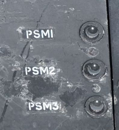
From memory bite indicators are: Power supply PSM1 - Power converter issues. PSM2 - +5VDC fail. PSM3 - +13VDC fail
Monitor board DS1 - Gyro spin issues - from memory
DS2 - servo no-go (round servo board problem on the gimbal assy)
DS3 - Overtemp
DS4 -
DS5 - Quantizer board problems (large board in the front gimbal area
DS6 - Bias wipe Computer board issue
The INU has some BITE (built in test) indicators. 3 can be found on the power supply externally and another 5 bite indicators can be found on the monitor board behind the panel beneath the power supply. Take this smaller cover off and the bottom cct bd will have 5 round disks - hopefully they will be black. If any are yellow this indicates that the unit has seen some fault during its life. These bite indicators can be easily reset with a magnet as they are magnetically latched.
From memory bite indicators are: Power supply PSM1 - Power converter issues. PSM2 - +5VDC fail. PSM3 - +13VDC fail
Monitor board DS1 - Gyro spin issues - from memory
DS2 - servo no-go (round servo board problem on the gimbal assy)
DS3 - Overtemp
DS4 -
DS5 - Quantizer board problems (large board in the front gimbal area
DS6 - Bias wipe Computer board issue
Thread Starter
Joined: Jan 2005
Posts: 68
Likes: 4
From: Munich/Gemany
Thanks Simon for the tips and efforts in digging that out. Just verified: While the sticker with the calibration data of the LTN72RH can be seen on the pictures I got from the seller, it got lost during transportation - the front just shows the sticky stuff of the sticker, but not the paper any more; zooming in on the seller's image gives a rough impression of the numbers:

But fortunately the memory is an EEPROM, so that should not "forget" the stuff easily and may still be readible:

Also easily verified that PSM1-3 have not been fired (or resetted):
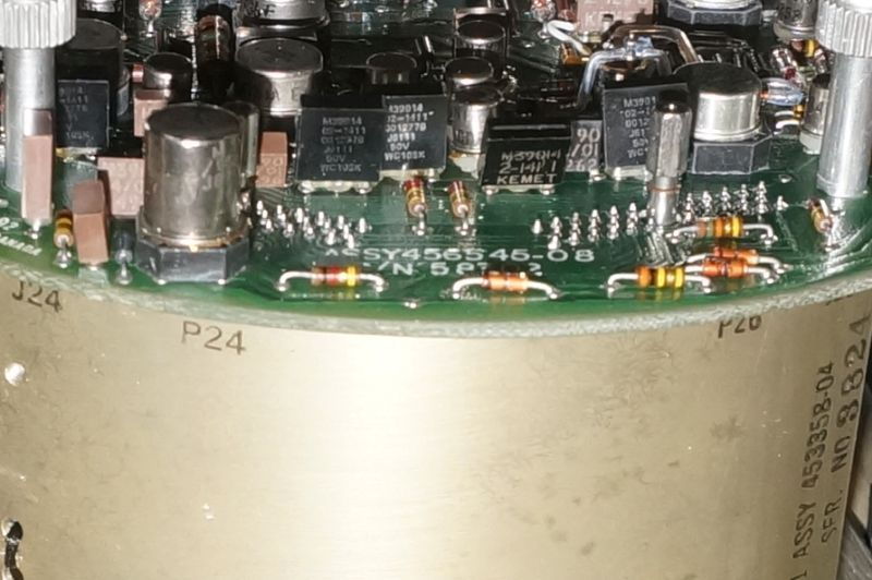
The platform trimmer board (the round one) is -08 - one which is not the worst as far as I understand your video:
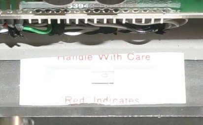
There is one of the little devices on the platform inidcating that there was no excessive shock (otherwise the small glass tube inside would have been broken and the color would have turned red) - so at least one good news:
The platform moves smoothly in all axes, but as mentioned via email - to my taste, there is quite some friction and I doubt that can be overcome by the torquer motors easily. At least the other INS systems I know (LTN51 and Ferranti INS) have less friction here. Looking at the nice video by Simon on youtube,
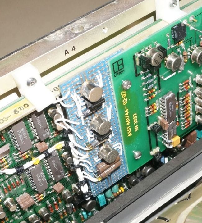
, the platform stops moving quite quickly there, too. But I guess there is no specification of friction in the platform maintenance manual? Although there is some corrosion on the chromatted aluminium parts, all plugs and other aluminiumparts look pretty OK. Quite strange looks a small PCB which definitively looks like some homebrew add-on done at the RAE in Boscombe Down:
Last but not least I have not been able to find DS1-DS5 (the only external flap on the rear covers some plug and beneath the power supply there are no indicatiors):
But fortunately the memory is an EEPROM, so that should not "forget" the stuff easily and may still be readible:
Also easily verified that PSM1-3 have not been fired (or resetted):
The platform trimmer board (the round one) is -08 - one which is not the worst as far as I understand your video:
There is one of the little devices on the platform inidcating that there was no excessive shock (otherwise the small glass tube inside would have been broken and the color would have turned red) - so at least one good news:
The platform moves smoothly in all axes, but as mentioned via email - to my taste, there is quite some friction and I doubt that can be overcome by the torquer motors easily. At least the other INS systems I know (LTN51 and Ferranti INS) have less friction here. Looking at the nice video by Simon on youtube,
Last but not least I have not been able to find DS1-DS5 (the only external flap on the rear covers some plug and beneath the power supply there are no indicatiors):
Last edited by baigar; 21st January 2023 at 17:43. Reason: Added two more pictures...
Joined: Jan 2023
Posts: 13
Likes: 0
From: Adelaide
The bias figures are not readable. My best guess for the GBX,GBY, GBZ values are: GBX: 7770 3600 GBY: 0015 2200 GBZ: 0010 0000. For info bias figures are between 7765 0000 and 0024 0000. Remembering that these are octal values with the middle figure being 0000 0000.
If the unit turns on, the first thing I would do as an absolute priority is to get the bias figures from the core memory. Procedure is:
MSU to Stby (remove small grey cover from msu - 2 scews). Turn rotary knob to bias. The write down the bias figures as shown on the CDU. CDU rotary knob should be in 'Pos' and wpt thumbwheel at 0
GBX (wpt 0)
GBY (wpt 1)
GBZ (wpt 2)
SFX (wpt 3)
SFY (wpt 4)
SFZ (wpt 5)
Once you have these figures written down you then have some sort of insurance policy against memory wipes.
Turn bias switch back to 'off' and you can then switch msu off or continue to align.
Joined: Jan 2023
Posts: 13
Likes: 0
From: Adelaide
With regard to the Boscombe Down cct board mod. I have not seen this on any unit before, so this unit must have been their test bed. I did help the guys at Boscombe Downs a few times in their workshop but was not aware they were modifying the units. It looks like its attached to the Qantizer cct bd, which is the large long board next to the platform. It may have been a data collection board. The qantizer board receives the raw acceleration data from the accelerometers and converts it into velocities and distance and then sends that data to the computer boards. The other boards in the gimbal area are: Gyro spin board, Temp control board, frequency control board (2 cct boards - one on top of the other, and the other board is the 26v aux pwr supply.
Joined: Jan 2023
Posts: 13
Likes: 0
From: Adelaide
I wouldn't be too worried about the excess friction in the gimbal. The excess friction would cause high drift on long flights. Something that you will not be doing.
The main priority is to get the unit to turn on without smoke coming out :-)
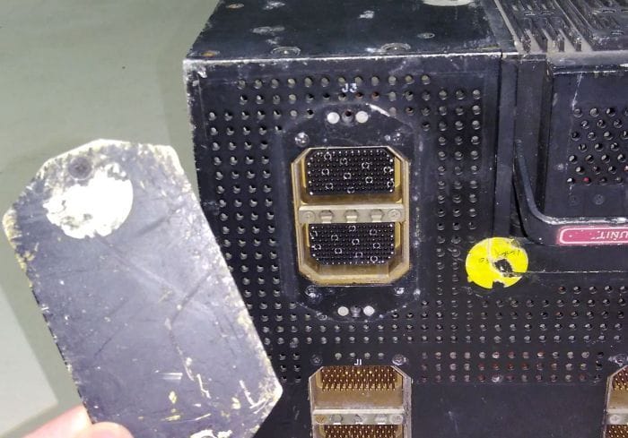
Looking at the pins on the rear end, they look okay. The main ones to worry about are the power and ground pins, they should be clean.
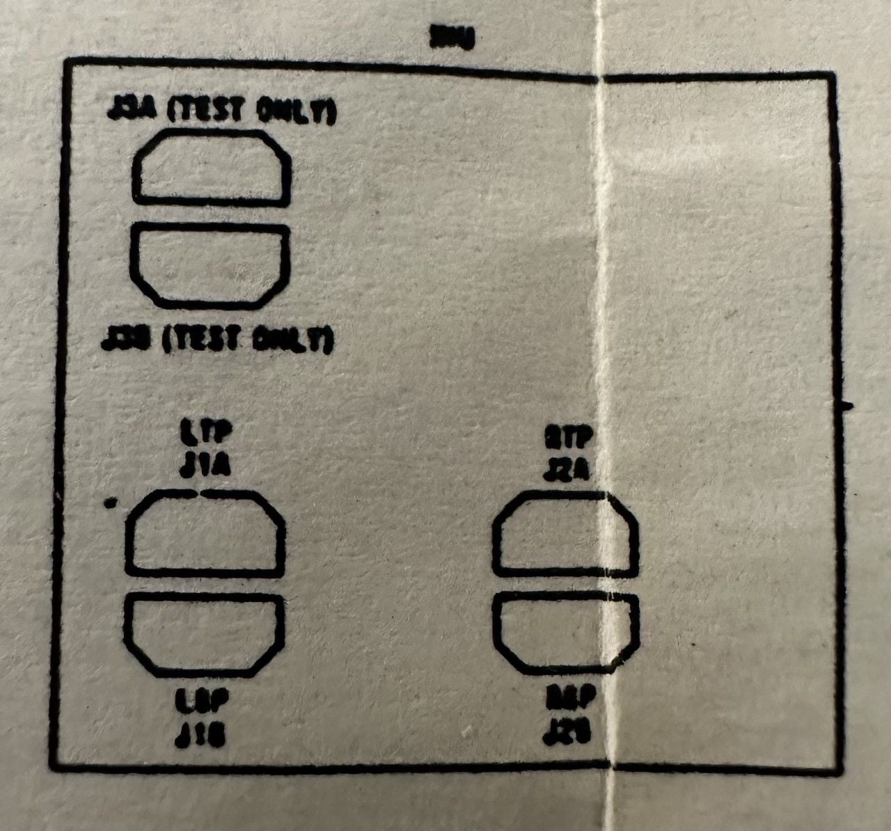
FYI - the top rear port (J3) is a test plug for the workshop.
FYI - I'm also trying to get my posting count up as I am unable to post pics until I have at least 8 posts on this forum. :-)
The main priority is to get the unit to turn on without smoke coming out :-)
Looking at the pins on the rear end, they look okay. The main ones to worry about are the power and ground pins, they should be clean.
FYI - the top rear port (J3) is a test plug for the workshop.
FYI - I'm also trying to get my posting count up as I am unable to post pics until I have at least 8 posts on this forum. :-)
Joined: Jan 2023
Posts: 13
Likes: 0
From: Adelaide
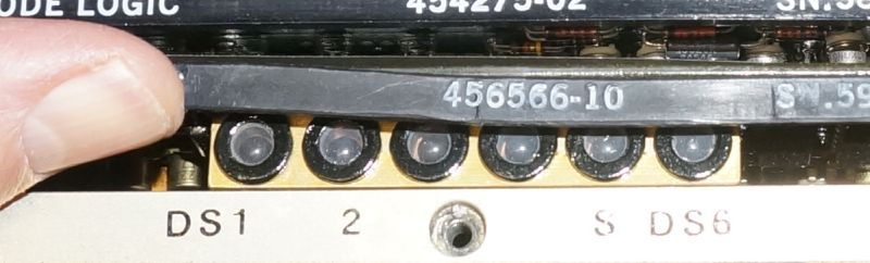
With regard to the hidden BITE indicators, they can be found behind the smaller black circuit board side cover, found just under the power supply which you removed in the pic above. 9 or so screws to undo. The monitor board is at the bottom, and you may have to slightly move the handle so as to view the bite indicators.
DS1 on the left and DS6 on the right.
DS1 on the left and DS6 on the right.
Joined: Jan 2023
Posts: 13
Likes: 0
From: Adelaide
Another note of caution. The unit like to run hot. In that the gimbal assembly requires a lot of heat to keep the gyros happy. The front of the unit will be quite hot to touch, whereas the rear of the unit where all the computer cards are likes to be at a cooler temp. When installed in an aircraft there is a constant movement of air thru the rear of the unit. If you get it up and running I would place a fan at the back of the unit to force air thru the rear which will then escape thru the underside of the unit.
The front side covers of the INU can be removed if there if a lot of fluff stuck in the heat exchanges. This fluff can be removed by a strong brush, just make sure the top lid if firmly in place so that nothing gets into the gimbal area. These older mechanical systems are a little finicky. :-)
The front side covers of the INU can be removed if there if a lot of fluff stuck in the heat exchanges. This fluff can be removed by a strong brush, just make sure the top lid if firmly in place so that nothing gets into the gimbal area. These older mechanical systems are a little finicky. :-)
Thread Starter
Joined: Jan 2005
Posts: 68
Likes: 4
From: Munich/Gemany
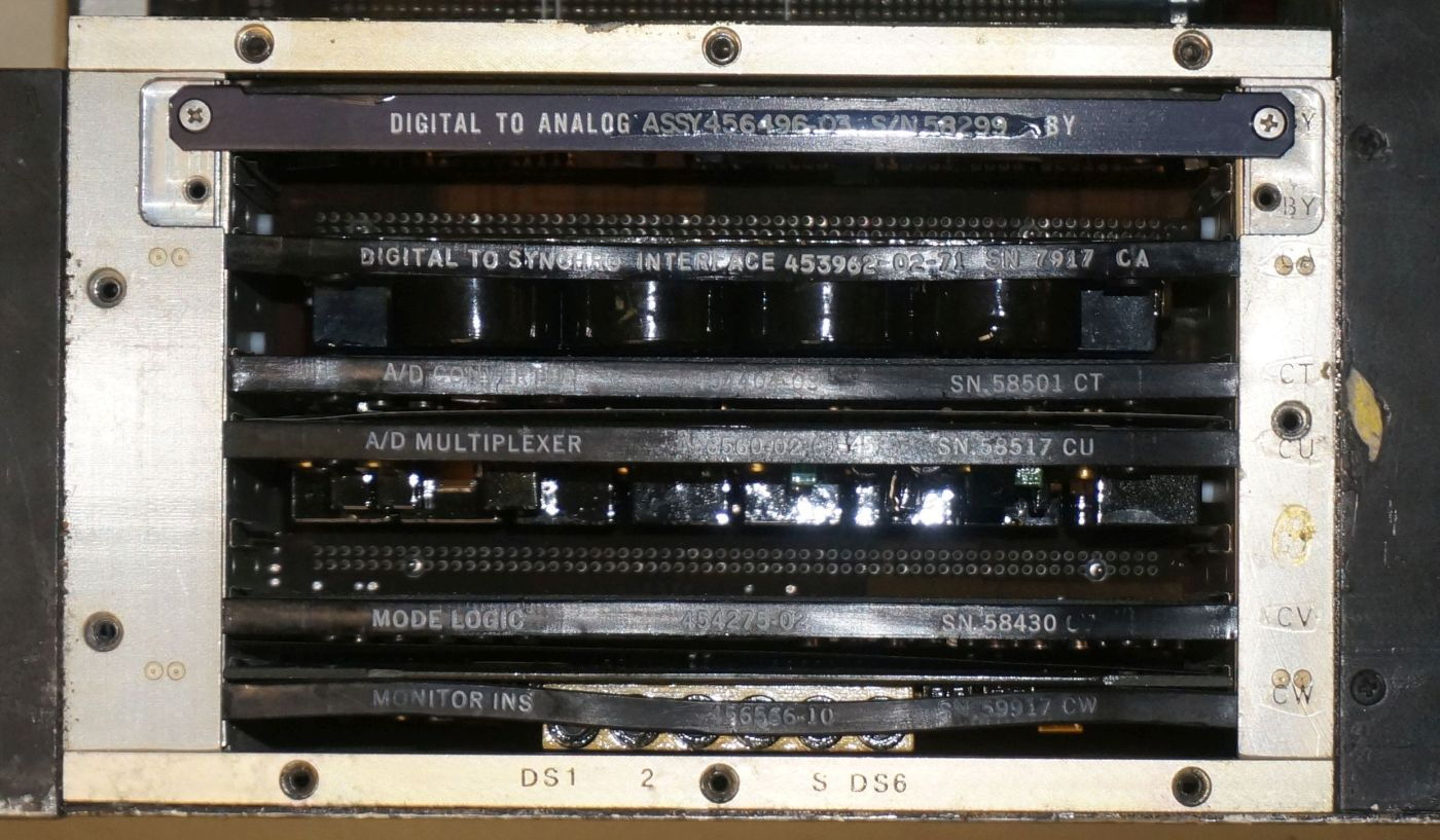
Hi Simon, thanks for the feedback and the additional hint. Found the indicators (they have been hidden behind the label of the lowest PCB) and no one is triggered:
But probably discovered the no-go under that panel as there seem to be two boards missing here: Slot BY (2nd from top is empty) and there
is a open plug/empty slot between CU and CV (3rd from bottom):
A pinout of the "workshop-plug" J3 would be quite helpful as this surely has access to all supply voltages - so it would be easy checking for shorted caps there. Thanks also for the hint on heat philisophy in the LTN72. Of course I am aware from my experienct that slip rings and bearings to not like dust at all ;-)
Last edited by baigar; 22nd January 2023 at 10:43. Reason: Grammar & added J3.
Joined: Jan 2023
Posts: 13
Likes: 0
From: Adelaide
Well that's weird. Missing one of the D/A boards. The other missing board is not an issue. The board above the Mode board is an optional board (Radio Navigation Interface board - RNI). Not required for this INU.
But with regard to the missing DA board, it should operate without. It's just a board that converts digital pitch/roll signals to analog format for some older avionics.
But with regard to the missing DA board, it should operate without. It's just a board that converts digital pitch/roll signals to analog format for some older avionics.
Joined: Jan 2023
Posts: 13
Likes: 0
From: Adelaide
Initialization of the INU.
The INU goes thru a number of statuses in order to complete a full alignment.
Status 90: MSU to STBY, Power applied to gimbal, heaters. Gimbal is forced into a cage mode and held steady whilst the gyros come up to speed. Approx. 50 seconds
Status 80: Once the gyros are up to temp and speed the caging system is released and the gyros now run the gimbal. The gimbal is now at a local level state. The INU is held in this state for a further 2 minutes.
Status 70: Course alignment where it starts to calculate true heading via slewing of the azimuth gimbal. Lasts for 3 minutes
Status 60: True heading is calculated and finalised. 1 minute
Status 50: True heading is now available via the CDU
Status 40: The beginning of fine alignment. Lasts around 3 minutes
Status 10: Finalising fine alignment. Lasts around 4 minutes.
Status 02: Alignment complete. INU can switch to NAV mode on the MSU
Total alignment time is 15 minutes
The INU can be used in two modes. One where the INU requires the computer to be fully functional and a full alignment is successfully completed. The other mode is ATT mode where the computer is shutdown and only the raw attitude info from the gimbal is fed to instruments.
To prepare INU for first turn on.
Side cct bd black panels and gimbal top black cover to be removed for initial test.
INU requires 115vac 400hz and +28VDC for initial turn on. Due to the high heating requirements at turn on, a lot of current will be required initially.
Switch the CDU rotary switch to DSR TK/STS
When the MSU is turned to STBY – power is sent to the INU and cage mode will commence instantly.
To ensure the gimbal has the ability to drive the gimbal it’s best to offset the gimbal prior to power up. Do this by manually moving the gimbal. Move the outer roll by 45 degrees, move the azimuth by 45 degrees and slightly offset the pitch as per my pic. The 8 OPAmps on the round servo board are in charge of driving the gimbal during cage mode (see pic). 2 for each axis (O/R, I/R, Az, Pitch). If the gimbal just spins wildly at turn on, then turn off immediately. Replacing the faulty amps will fix the problem.
If the gimbal cages then this is good news. Gyros should then spin up and upon successful spin up the INU will go to Status 80.
The INU will remain in status 80 until a lat and long has been entered into the cdu and the MSU is turned to ALIGN.
In instances where the INU has been transported between hemispheres and not been turned on, the computer may show an error code as it is unable to recognize its recent (last known) turn on location. This error can be over ridden by recycling the INU. Action Malfunction code of 5-03 will be displayed.
If the INU does turn on the first priority is to collect the bias figures from the core memory. Turn the switch under the hidden panel on the MSU to BIAS and flick waypoint wheel to 0. Write down the 6 bias figures – Move waypoint thumbwheel from 0 to 5. Once complete turn the bias switch back.
If you get this far, then things are going extremely well. Once lat and long has been entered into the CDU and MSU has been set to ALIGN, then just watch the status. If it gets to Status 40 or 10 and a flashing warn comes up (AMF 2-19 / 2-20 / 2-21) this is expected as the unit is so old and out of calibration. If you get this far then we can perform some calibration to try and trick it into performing a successful alignment. Usually takes a week to fully calibrate an INU in a workshop environment.
Let’s see how far you get 😊
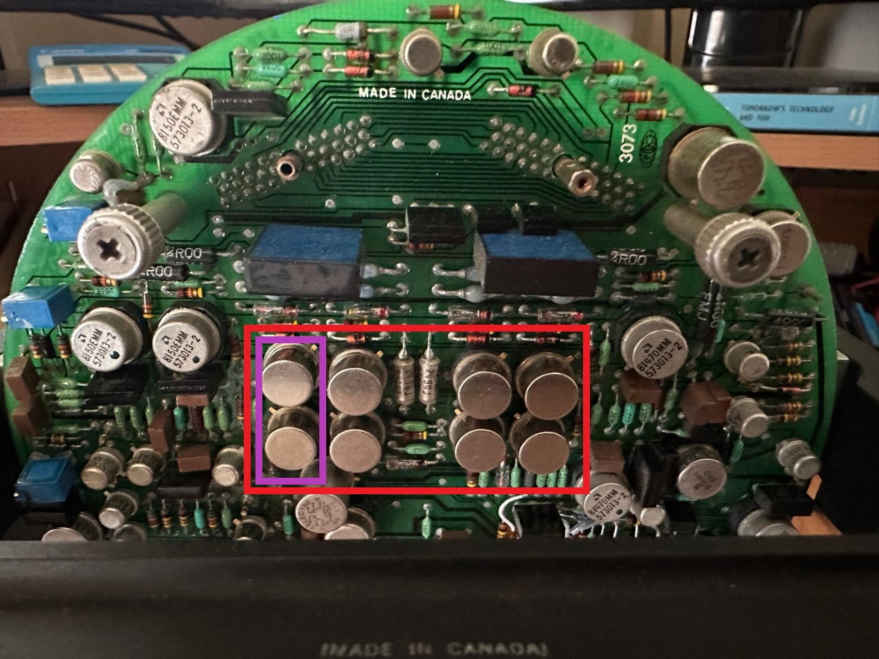
OpAmps on Servo Bd
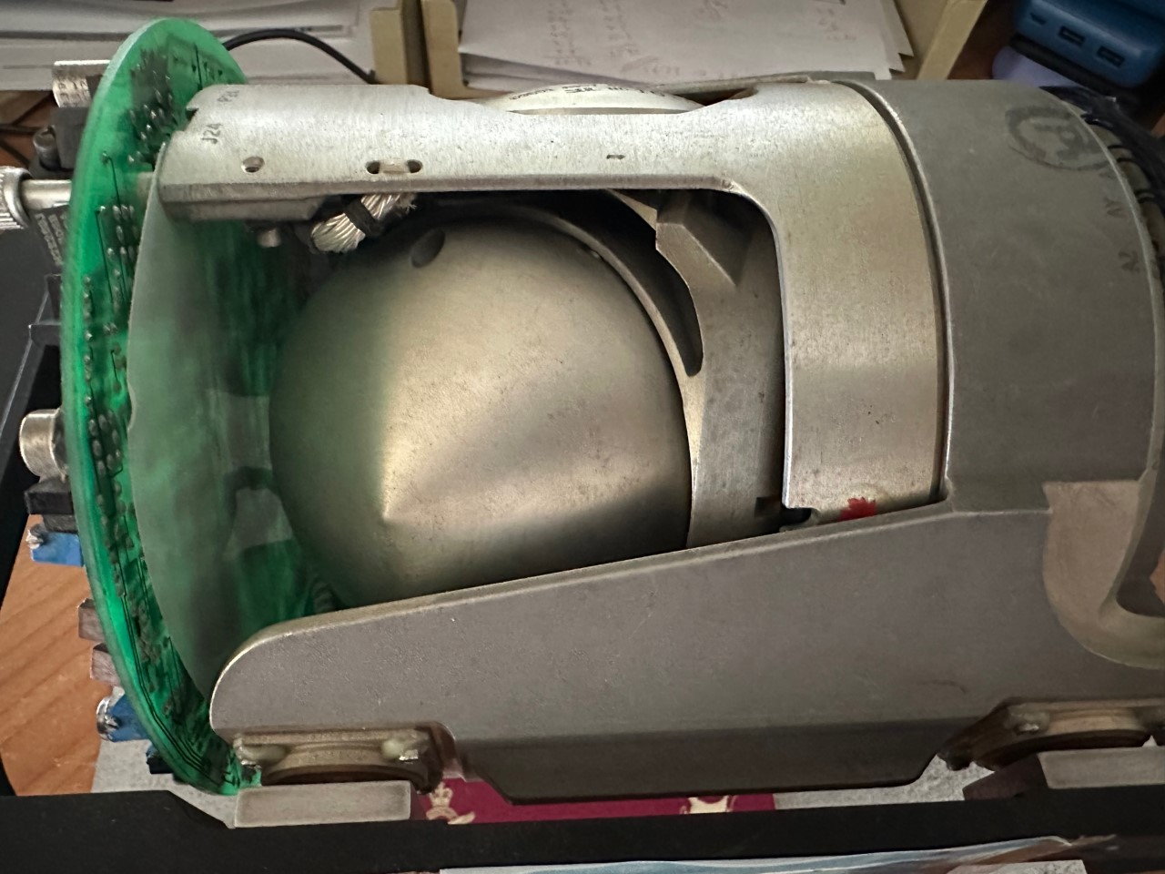
O/R, Azimuth and pitch offset manually prior to first turn on
The INU goes thru a number of statuses in order to complete a full alignment.
Status 90: MSU to STBY, Power applied to gimbal, heaters. Gimbal is forced into a cage mode and held steady whilst the gyros come up to speed. Approx. 50 seconds
Status 80: Once the gyros are up to temp and speed the caging system is released and the gyros now run the gimbal. The gimbal is now at a local level state. The INU is held in this state for a further 2 minutes.
Status 70: Course alignment where it starts to calculate true heading via slewing of the azimuth gimbal. Lasts for 3 minutes
Status 60: True heading is calculated and finalised. 1 minute
Status 50: True heading is now available via the CDU
Status 40: The beginning of fine alignment. Lasts around 3 minutes
Status 10: Finalising fine alignment. Lasts around 4 minutes.
Status 02: Alignment complete. INU can switch to NAV mode on the MSU
Total alignment time is 15 minutes
The INU can be used in two modes. One where the INU requires the computer to be fully functional and a full alignment is successfully completed. The other mode is ATT mode where the computer is shutdown and only the raw attitude info from the gimbal is fed to instruments.
To prepare INU for first turn on.
Side cct bd black panels and gimbal top black cover to be removed for initial test.
INU requires 115vac 400hz and +28VDC for initial turn on. Due to the high heating requirements at turn on, a lot of current will be required initially.
Switch the CDU rotary switch to DSR TK/STS
When the MSU is turned to STBY – power is sent to the INU and cage mode will commence instantly.
To ensure the gimbal has the ability to drive the gimbal it’s best to offset the gimbal prior to power up. Do this by manually moving the gimbal. Move the outer roll by 45 degrees, move the azimuth by 45 degrees and slightly offset the pitch as per my pic. The 8 OPAmps on the round servo board are in charge of driving the gimbal during cage mode (see pic). 2 for each axis (O/R, I/R, Az, Pitch). If the gimbal just spins wildly at turn on, then turn off immediately. Replacing the faulty amps will fix the problem.
If the gimbal cages then this is good news. Gyros should then spin up and upon successful spin up the INU will go to Status 80.
The INU will remain in status 80 until a lat and long has been entered into the cdu and the MSU is turned to ALIGN.
In instances where the INU has been transported between hemispheres and not been turned on, the computer may show an error code as it is unable to recognize its recent (last known) turn on location. This error can be over ridden by recycling the INU. Action Malfunction code of 5-03 will be displayed.
If the INU does turn on the first priority is to collect the bias figures from the core memory. Turn the switch under the hidden panel on the MSU to BIAS and flick waypoint wheel to 0. Write down the 6 bias figures – Move waypoint thumbwheel from 0 to 5. Once complete turn the bias switch back.
If you get this far, then things are going extremely well. Once lat and long has been entered into the CDU and MSU has been set to ALIGN, then just watch the status. If it gets to Status 40 or 10 and a flashing warn comes up (AMF 2-19 / 2-20 / 2-21) this is expected as the unit is so old and out of calibration. If you get this far then we can perform some calibration to try and trick it into performing a successful alignment. Usually takes a week to fully calibrate an INU in a workshop environment.
Let’s see how far you get 😊
OpAmps on Servo Bd
O/R, Azimuth and pitch offset manually prior to first turn on
Thread Starter
Joined: Jan 2005
Posts: 68
Likes: 4
From: Munich/Gemany
Thanks Simon again for the interesting and helpful information (your efforts are highly appreciated); I will definitively follow your advice and in case of problems swapping the driver OpAmps is not a problem at all ;-)
Do you have got an idea how much power is required on the rails? I have no problem with 115VAC/400Hz as I built a powerful inverter, but currently its 28VDC output is limited to 2A.
INU requires 115vac 400hz and +28VDC for initial turn on. Due to the high heating requirements at turn on, a lot of current will be required initially.
Joined: Jan 2023
Posts: 13
Likes: 0
From: Adelaide
Minimal current needed for the 28v. This is really only required as a safety interlock for initialisation. It needs to see that 28v is present so that if 115 is lost in flight it can survive on the backup. In reality as soon as the ini turns on the 28 can be removed. You’ll get a warning but the inu will still operate as normal.
when the big day arrives, remember to take a video of the gimbal starting up, so we can see any issues and advise. :-)
when the big day arrives, remember to take a video of the gimbal starting up, so we can see any issues and advise. :-)
Thread Starter
Joined: Jan 2005
Posts: 68
Likes: 4
From: Munich/Gemany
Today connected wires to the mode panel and the CDU and did some measurements to verify what my pinouts tell me. For both panels I seem to have the correct pinouts and the CDU even sends out digital data when powered up (28V DC, drawing around 0.5Amps):
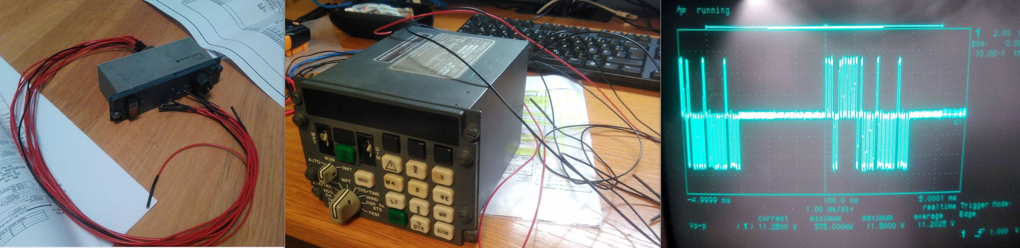
But I am somewhat struggling with the pinout of the plugs on the rear side of the LTN72...

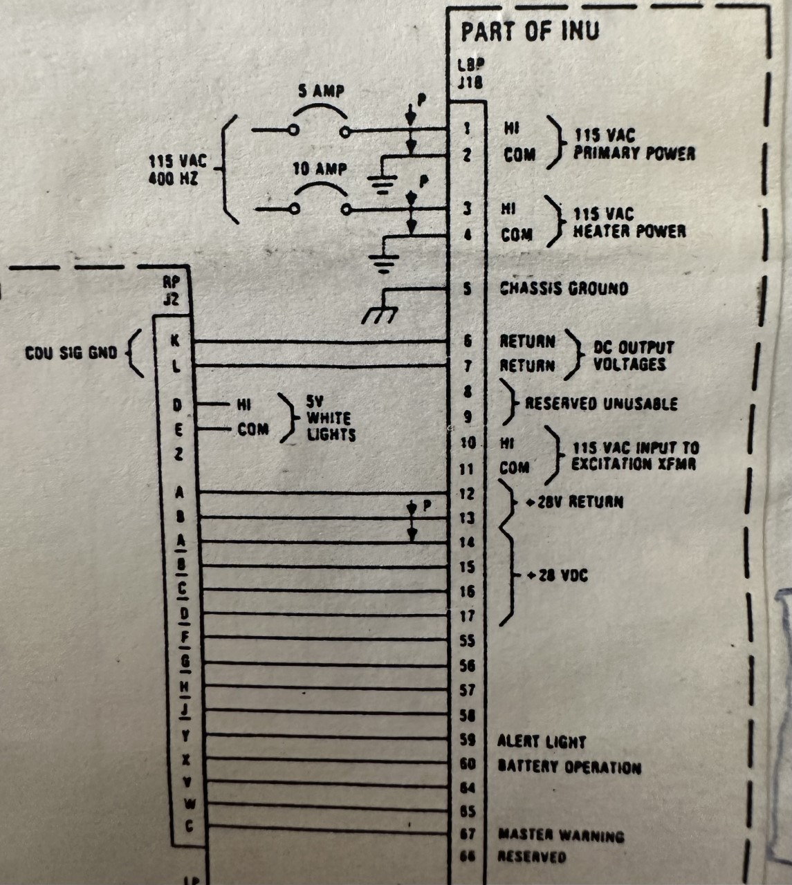
...here my pinout says gound on J2A 7, J1B 2,4. But I do not see the ground pins being connected. So am I right, that the A parts are the upper halves and the B the lower ones and that the numbers given on the plugs are OK? From my DC10 (Laker airways) schematics I see that 115VAC should be connected to J1B, pins 1 and 3 and 28VAC (excitation for attitude outputs) is to be sent to J2A pin 6.
But I am somewhat struggling with the pinout of the plugs on the rear side of the LTN72...
...here my pinout says gound on J2A 7, J1B 2,4. But I do not see the ground pins being connected. So am I right, that the A parts are the upper halves and the B the lower ones and that the numbers given on the plugs are OK? From my DC10 (Laker airways) schematics I see that 115VAC should be connected to J1B, pins 1 and 3 and 28VAC (excitation for attitude outputs) is to be sent to J2A pin 6.
Joined: Jan 2023
Posts: 13
Likes: 0
From: Adelaide
The power pin outs are the same for all LTN-72s and LTN-92 INUS
115VAC 400hz (Primary Power) 5 amps
High - J1B Pin 1
Common - J1B Pin 2
115Vac 400Hz (Heater Power) 10 amps
High - J1B Pin 3
Common - J1B Pin 4
J1B Pin 5 is chassis ground. This is connected to the aircraft frame / INU tray
Battery (+28VDC)
+28VDC - J2B Pins 3 and 4
-28VDC - J2A Pins 3 and 4 (this is battery return)
No other power is required to run the INU. All other voltages are created by the INU and fed throughout the unit.
Your assumptions on the plug layout are correct. A is top and B is bottom.
Thread Starter
Joined: Jan 2005
Posts: 68
Likes: 4
From: Munich/Gemany
Wiring of the LTN72 to Mode-Panel and CDU is complete with all required connections. Impedances look good and Inverter is ready with a 3A fuse permitting around 320W maximum into the INS. First try will be without heaters, but will re-check wiring next weekend before giving the smoke an opportunity to show up in my lab ;-) Stay tuned (event of first power-up will be recorded on video)...
Joined: Jan 2023
Posts: 13
Likes: 0
From: Adelaide
This is a very big moment.
Remember when power (specifically 115vac 400hz) is first supplied to the unit (before switching the MSU on) there'll be a high pitched whining noise from the back of the INU. This is good.
Regarding the video, it's only important to capture what the gimbal does at turn on (video to show the CDU display + Gimbal movement + your hand switching MSU to stby - if possible). We can gain a lot of knowledge from what the gimbal does at switch on.
If it does turn on without smoke - remember to write down the bias figures (as a priority) - as previously mentioned in the thread.
This is what I expect at first turn on.
60% chance that nothing happens - other than smoke from the power supply (not good)
30% chance the gimbal cages (or tries to) and then maybe spins wildly after cage mode is complete - possibly due to failed gyros/accels/servo bd. (possibly be able to fix)
5% chance that system tries to align but then fails due to the calibration being way off (High possibility to fix with some calibration) Action/Malfunction code will be displayed and a flashing 'Warn" on the CDU.
5% chance of successful alignment - nothing to worry about.
Good luck. :-)