Initialization of the INU.
The INU goes thru a number of statuses in order to complete a full alignment.
Status 90: MSU to STBY, Power applied to gimbal, heaters. Gimbal is forced into a cage mode and held steady whilst the gyros come up to speed. Approx. 50 seconds
Status 80: Once the gyros are up to temp and speed the caging system is released and the gyros now run the gimbal. The gimbal is now at a local level state. The INU is held in this state for a further 2 minutes.
Status 70: Course alignment where it starts to calculate true heading via slewing of the azimuth gimbal. Lasts for 3 minutes
Status 60: True heading is calculated and finalised. 1 minute
Status 50: True heading is now available via the CDU
Status 40: The beginning of fine alignment. Lasts around 3 minutes
Status 10: Finalising fine alignment. Lasts around 4 minutes.
Status 02: Alignment complete. INU can switch to NAV mode on the MSU
Total alignment time is 15 minutes
The INU can be used in two modes. One where the INU requires the computer to be fully functional and a full alignment is successfully completed. The other mode is ATT mode where the computer is shutdown and only the raw attitude info from the gimbal is fed to instruments.
To prepare INU for first turn on.
Side cct bd black panels and gimbal top black cover to be removed for initial test.
INU requires 115vac 400hz and +28VDC for initial turn on. Due to the high heating requirements at turn on, a lot of current will be required initially.
Switch the CDU rotary switch to DSR TK/STS
When the MSU is turned to STBY – power is sent to the INU and cage mode will commence instantly.
To ensure the gimbal has the ability to drive the gimbal it’s best to offset the gimbal prior to power up. Do this by manually moving the gimbal. Move the outer roll by 45 degrees, move the azimuth by 45 degrees and slightly offset the pitch as per my pic. The 8 OPAmps on the round servo board are in charge of driving the gimbal during cage mode (see pic). 2 for each axis (O/R, I/R, Az, Pitch). If the gimbal just spins wildly at turn on, then turn off immediately. Replacing the faulty amps will fix the problem.
If the gimbal cages then this is good news. Gyros should then spin up and upon successful spin up the INU will go to Status 80.
The INU will remain in status 80 until a lat and long has been entered into the cdu and the MSU is turned to ALIGN.
In instances where the INU has been transported between hemispheres and not been turned on, the computer may show an error code as it is unable to recognize its recent (last known) turn on location. This error can be over ridden by recycling the INU. Action Malfunction code of 5-03 will be displayed.
If the INU does turn on the first priority is to collect the bias figures from the core memory. Turn the switch under the hidden panel on the MSU to BIAS and flick waypoint wheel to 0. Write down the 6 bias figures – Move waypoint thumbwheel from 0 to 5. Once complete turn the bias switch back.
If you get this far, then things are going extremely well. Once lat and long has been entered into the CDU and MSU has been set to ALIGN, then just watch the status. If it gets to Status 40 or 10 and a flashing warn comes up (AMF 2-19 / 2-20 / 2-21) this is expected as the unit is so old and out of calibration. If you get this far then we can perform some calibration to try and trick it into performing a successful alignment. Usually takes a week to fully calibrate an INU in a workshop environment.
Let’s see how far you get 😊
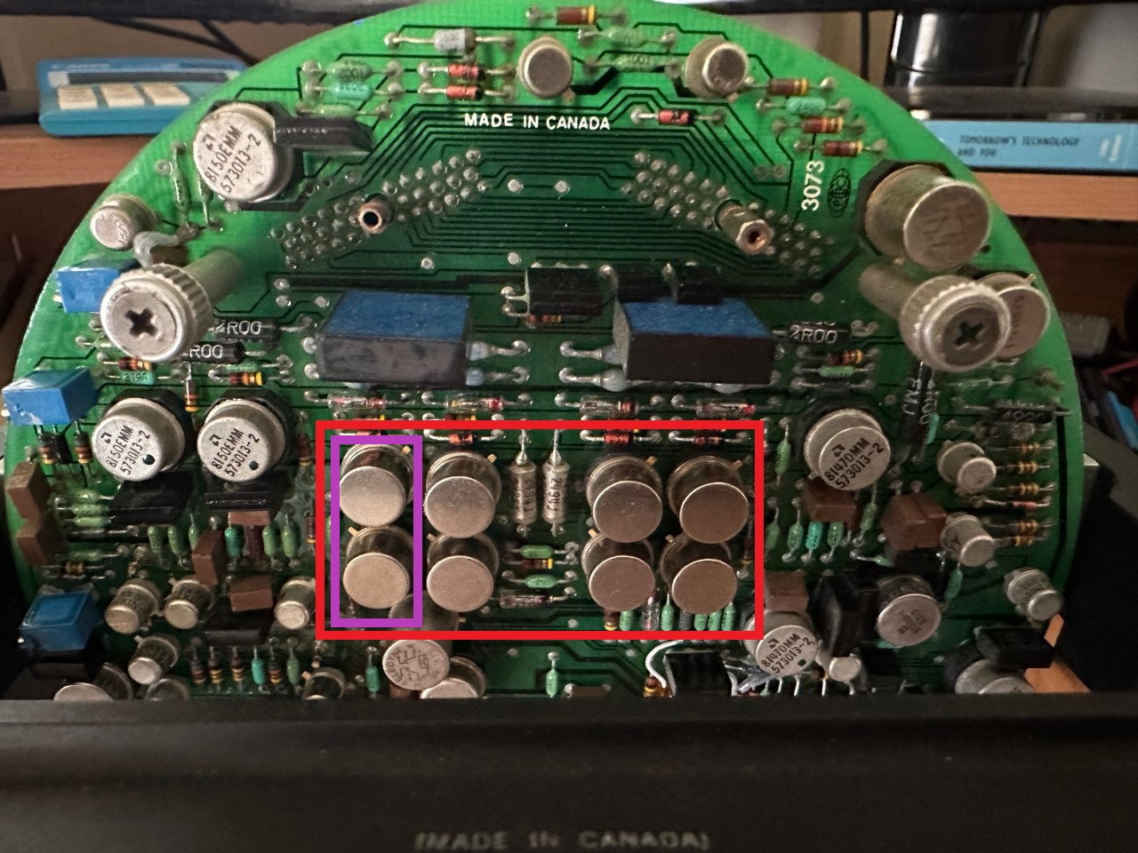 OpAmps on Servo Bd
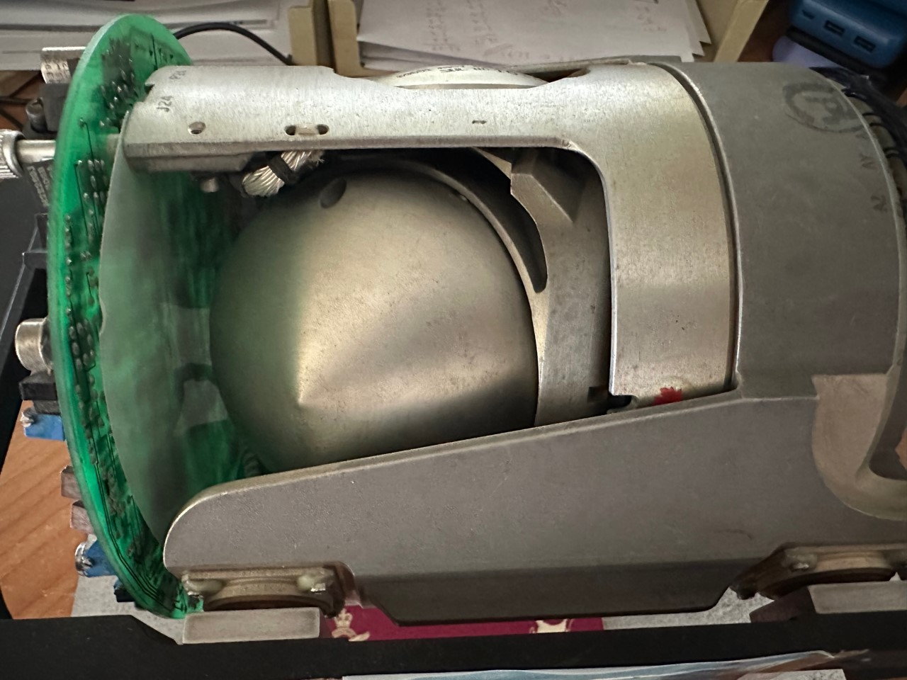 O/R, Azimuth and pitch offset manually prior to first turn on