


Alaska Airlines 737-900 MAX loses a door in-flight out of PDX

Join Date: Apr 2015
Location: Under the radar, over the rainbow
Posts: 794
Received 0 Likes
on
0 Posts

Join Date: Apr 2015
Location: Under the radar, over the rainbow
Posts: 794
Received 0 Likes
on
0 Posts
I agree. They're strong. But unless the cable tie was holding the stop pin tightly against its pad, or the pin was tightened into solid contact with the pad, the near end (inboard) of the loop would be pulled upward and the pin and pad would not remain in vertical alignment.
Last edited by OldnGrounded; 8th Feb 2024 at 23:43. Reason: Clarify "near end"
I keep looking at the zip tie picture. The white rectangle in the middle of the stop pad looks at first like the head of a cable tie. But there's the same feature on the stop pad above also; it seems to be a pixelated image of the adjuster screw on the pad.
With that rectangle covered up, what's left doesn't look unlike a zip tie, but to me the uncanny resemblance is gone. And if an adjuster screw can look like a cable tie head, perhaps something else could look like the rest of the tie. I'm just wondering how sure we are it really is a zip tie.
With that rectangle covered up, what's left doesn't look unlike a zip tie, but to me the uncanny resemblance is gone. And if an adjuster screw can look like a cable tie head, perhaps something else could look like the rest of the tie. I'm just wondering how sure we are it really is a zip tie.
Join Date: Sep 2019
Location: Vancouver
Posts: 11
Likes: 0
Received 0 Likes
on
0 Posts
Maintenance on 737 Max 9 and 900ER door plugs must be occurring on a frequent basis. I wonder if Boeing has any documented events where bolts were missing after completion of maintenance and the door plug sprang open after the work was concluded - but before the plane had ever been flight tested again. Would they have these records? Could this incident really be a complete one-off?
Thinking about this a bit more, whilst pulling the door down, the guide tracks will position the stop pins / pads correctly relative to each other at the top of the door but it is probably necessary to keep pulling inwards and downwards to ensure that the lower stop pins / pads are positioned correctly. This is because the hinge posts have substantial free inboard-outboard movement available at the floor brackets (see Chris Brady�s last video) so need to be pulled in the inboard direction to ensure the pins clear the pads as they move down.
I keep looking at the zip tie picture. The white rectangle in the middle of the stop pad looks at first like the head of a cable tie. But there's the same feature on the stop pad above also; it seems to be a pixelated image of the adjuster screw on the pad.
With that rectangle covered up, what's left doesn't look unlike a zip tie, but to me the uncanny resemblance is gone. And if an adjuster screw can look like a cable tie head, perhaps something else could look like the rest of the tie. I'm just wondering how sure we are it really is a zip tie.
With that rectangle covered up, what's left doesn't look unlike a zip tie, but to me the uncanny resemblance is gone. And if an adjuster screw can look like a cable tie head, perhaps something else could look like the rest of the tie. I'm just wondering how sure we are it really is a zip tie.
Join Date: Jan 2024
Location: Scotland
Posts: 52
Likes: 0
Received 0 Likes
on
0 Posts
I agree. They're strong. But unless the cable tie was holding the stop pin tightly against its pad, or the pin was tightened into solid contact with the pad, the near end (inboard) of the loop would be pulled upward and the pin and pad would not remain in vertical alignment.

The stop pin faces are convex and the stop pad faces are concave giving a spherical seating. Correction - OH NO THEY AREN�T. Thanks subsequent contributors. A cable tie would be essentially in tension to keep the pins & pads engagaed. If that is a cable tie in the photo then you can see the horrible attraction of using one (or two) to hold the door / plug in place before fitting the locking bolts.
Last edited by Europa01; 12th Feb 2024 at 08:16. Reason: Corrections
Join Date: Jan 2024
Location: UK
Posts: 45
Likes: 0
Received 0 Likes
on
0 Posts
There is evidence of where the roller was when the fracture happened - the torn off tab has a reverse curvature to it that is below the bolt hole, where the middle arrow is pointing. This is where the roller was pushing when the tab sheared off. The roller starts in the pocket entirely above the blue rectangle when the door is fully seated.

Also note there is damage to the other side of the track on the left a little lower down where the paint is missing. This is the aft guide we are looking at.
Join Date: Jan 2024
Location: UK
Posts: 45
Likes: 0
Received 0 Likes
on
0 Posts
The stop pin faces are convex and the stop pad faces are concave giving a spherical seating. A cable tie would be essentially in tension to keep the pins & pads engagaed. If that is a cable tie in the photo then you can see the horrible attraction of using one (or two) to hold the door / plug in place before fitting the locking bolts.

If the aren't flat, that's the first time I've seen that on any door stops.
Join Date: Jan 2024
Location: UK
Posts: 45
Likes: 0
Received 0 Likes
on
0 Posts
Join Date: Jan 2024
Location: Naples
Posts: 15
Likes: 0
Received 0 Likes
on
0 Posts
Very likely that they are flat. In combination with the compensating nature of the swivel type contact shoe it provides the highest chance to have a flat clean contact.
If you go sherical one would need to match 24 centers to prevent point contact. Form deviations of the sherical faces come on top of it.
Mission impossible already with 2 perfectlly spherical pins slightly out of position.
Make a sketch and you will see it will only work for 1 pin.
Join Date: Dec 2014
Location: Schiphol
Posts: 480
Likes: 0
Received 0 Likes
on
0 Posts
Spring and over-center?
what if �
Causal context �senator Cantwell letter to FAA administrator of Jan 26, 2023 (on NG and fearing for MAX) on (legally CFR) Boeing non-compliant production and quality systems� plus senior management not interested�
if these systems are implemented in an ERP context then the CFO side would probably be in the lead .. so big distance between decision maker and operations� know they don�t know and don�t want to know�
Standards at Spirit same, or according to Boeing itself (sending waves) even lower� (Onex taking billions out would also touch budgets here�)�
if the components are bad then their interfaces suffer, in these case even more because the operation itself is in turmoil (rates up and down, delays, extra re-work, re-work metal in final assembly ),
and since the Onex takeover in 2005 the parties are in multiple legal battles�
etcetera
Say: MURPHY
Murphy in devil detail shape � 2 plus 2 bolts are left out.. non-compliant in-complete not-airworthy plane goes into operation� starts carrying passengers
During 151 cycles the plug follows a dynamic path over the stops � weakening the various components �
the right hand forward bottom spring (or stops) fails�
the right hand forward over-center position is exited�. (I would like to understand this better)� 1st pressure change�
the door moves upward AND outward (explaining the guide fracture shape (bending L to CL shape)� 2nd pressure change �
after �bowing� open (C shape part)�now in one rip the lower L part of the guide gives way, fully releasing the roller� door �explodes� outward while turning aft�3rd pressure change
door flips open 90-100 degrees outward while tearing aft, stripping bracket and spring halves from the forward lower hinge�
door departs � from 90-100 low position � passing under the horizontal stabiliser� without even scratching stab or fuselage ( no mention in NTSB prelim of any secondary damage ! )�
Interested in your views ;-)
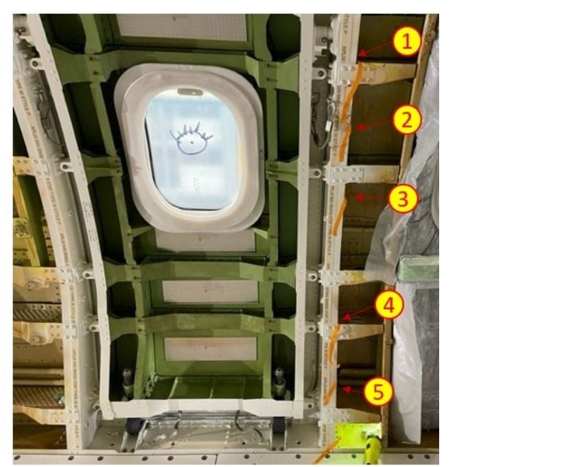
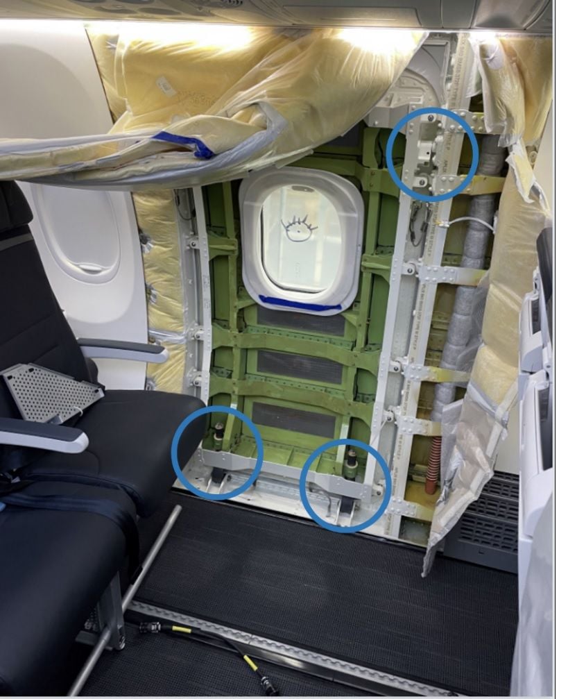
In Figure 16 there is a large conduit/piping between the ribs, fwd of the plug opening. This is not present in Figure 14.
Was this removed for access to fix the rivets, or is its installation the reason for the cabin furniture removal in the first place?
In Figure 16 there is what looks like a lanyard/cable tie attached to the fwd door restraint lanyard, passing in front of the conduit/piping. what is it and what is it for ?
In Figure 16, the cable tie is attached to the fwd 2nd up stop pad, most people would not bother to bend down and attach it there, they would attach it to the top stop pads for convenience. Why is it attached there?
In Figure 14 you can see that the 4 bolts etc. are installed, but not in Figure 16.
I keep looking at the zip tie picture. The white rectangle in the middle of the stop pad looks at first like the head of a cable tie. But there's the same feature on the stop pad above also; it seems to be a pixelated image of the adjuster screw on the pad.
With that rectangle covered up, what's left doesn't look unlike a zip tie, but to me the uncanny resemblance is gone. And if an adjuster screw can look like a cable tie head, perhaps something else could look like the rest of the tie. I'm just wondering how sure we are it really is a zip tie.
With that rectangle covered up, what's left doesn't look unlike a zip tie, but to me the uncanny resemblance is gone. And if an adjuster screw can look like a cable tie head, perhaps something else could look like the rest of the tie. I'm just wondering how sure we are it really is a zip tie.
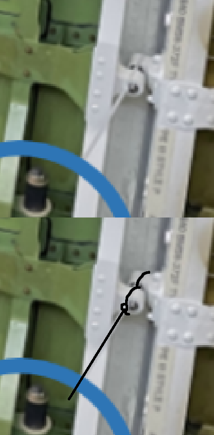
I wonder if the original photo has a higher resolution.
Join Date: Jan 2024
Location: UK
Posts: 45
Likes: 0
Received 0 Likes
on
0 Posts
The image in the report is 801x1007 pixels, so most likely they have something much clearer. Even with the limited detail in the report, I feel if the cable tie (assuming that is what it is) was in any way significant it would have been mentioned. I think it is more likely to have held a bag or flag as others have suggested.