


Alaska Airlines 737-900 MAX loses a door in-flight out of PDX

Again, the last posts have overlooked the window trim panel contribution to keeping the plug in position and from moving freely upwards, as mentioned by wbclay, repeated by TURIN and again by Loose rivets; not just a singular cable tie!
Any reports of the trim panel being found?
They are normally quite tightly held by various means including velcrow and closing trap strips, possibly a form of 1/4 turn faster; they would slot behind the lower vent panels too.
And I am not suggesting they would resist the decompression loads.
Any reports of the trim panel being found?
They are normally quite tightly held by various means including velcrow and closing trap strips, possibly a form of 1/4 turn faster; they would slot behind the lower vent panels too.
And I am not suggesting they would resist the decompression loads.

Join Date: May 2011
Location: U.S.
Posts: 84
Likes: 0
Received 0 Likes
on
0 Posts
Yes, all fair points.
Earlier in the thread there was some discussion about the strength of the two 'lift assist' springs and whether they would push the door plug up and out of the closed position in the absence of the lock bolts. Looking at the photo a couple of posts back, the one remaining spring does not look very substantial. To me, the only thing that makes sense is that the springs provide just enough force to allow the plug to be lifted safely by someone.
Earlier in the thread there was some discussion about the strength of the two 'lift assist' springs and whether they would push the door plug up and out of the closed position in the absence of the lock bolts. Looking at the photo a couple of posts back, the one remaining spring does not look very substantial. To me, the only thing that makes sense is that the springs provide just enough force to allow the plug to be lifted safely by someone.
It is not relevant at this stage, but please understand these are two unrelated things.

1) The springs are clearly strong enough to support the entire weight of the door plug, this has never been refuted. Whether extended, or compressed and retained by bolts, the springs are ALWAYS providing enough force to support the weight of the door plug.
2) Static friction either from the bolts (when properly installed), or from the door seals (in the absence of properly installed bolts) may prevent the door plug from translating upwards DESPITE the fact the springs are sufficiently strong to support the weight of the door plug.
Look at it this way: The fact that the door plug does not move upwards when the lower retention bolts are properly installed is not proof that the springs are not strong enough to support the door plug's weight. Right? The springs may be strong enough, but something is resisting their extension. Similarly, the fact that the door plug may require human assistance to lift it clear of the stops when "opening" is also not proof the springs are not strong enough to support the weight of the door plug. Two different things.
Otherwise ask yourself how the door plug ever left the aircraft.
Join Date: May 2011
Location: U.S.
Posts: 84
Likes: 0
Received 0 Likes
on
0 Posts
The cabin trim has to be attached to the structure. If it's attached to both plug door and adjacent fuselage it's possible that was enough to hold the door down. Over a period of flight there were bound to be some turbulence that could gradually shift the door.
Just a thought.
Just a thought.
Join Date: May 2011
Location: U.S.
Posts: 84
Likes: 0
Received 0 Likes
on
0 Posts
I remain unconvinced that the lift assist springs force is insufficient to raise the door/plug to its fullest amount.
In my earlier post #1211 of an analysis based on Chris Brady's video of the mechanics of how the door closes and opens, I'd said this:
"The door is pulled inwards until the hinges are closed � the door is now more or less flush with, and just inside, the line of the fuselage.
All the weight of the door is resting on the lift assist springs. The springs are fully extended with the hinge guide fittings in their maximum �up� position, hard up against the 2 locked nuts at the top of the hinge and spring assembly."
I now refer to the NTSB Report Fig 15 showing a photo of a door in a partly open state. If you zoom in to the visible bottom right of the door you can see the hinge assembly and the hinge guide fittings - they are hard up against the double lock nuts and washer. I accept that because of the angle of the door the entire door weight isn't being taken by the springs, but for me the likelihood is that the door would indeed be held at its maximum "up" position.
I give another reason for this to be the case. With the door held fully up by the springs there is a certainty that as the door is pulled closed the 12 stop fittings will pass over the top of their mating stop pads. This surely is an important feature, because if during closing the stop fittings impacted their stop pads (because the springs only held the door partly up its travel) there is obviously a possibility of damage to one or the other or both. Should this happen, but went unnoticed, unreported or uninspected there is a chance of such damage to critical primary structure causing door problems in the future.
People are confusing two different things. The springs CAN be strong enough to support the weight of the door plug, AND the door plug CAN be held at the bottom in the absence of bolts.*
Both can be true, one does not preclude the other.
*by friction of the seals and friction of the interior trim against the plug (TURIN's post #1673), or by a zip tie, or by a loosely placed bolt in the upper aft door guide.
Join Date: May 2011
Location: U.S.
Posts: 84
Likes: 0
Received 0 Likes
on
0 Posts
I can't take any credit for this, as it's been pointed out to me privately by a forumite, but this is an interesting photo (P17, Figure 16) from the NTSB report (my blow-up):
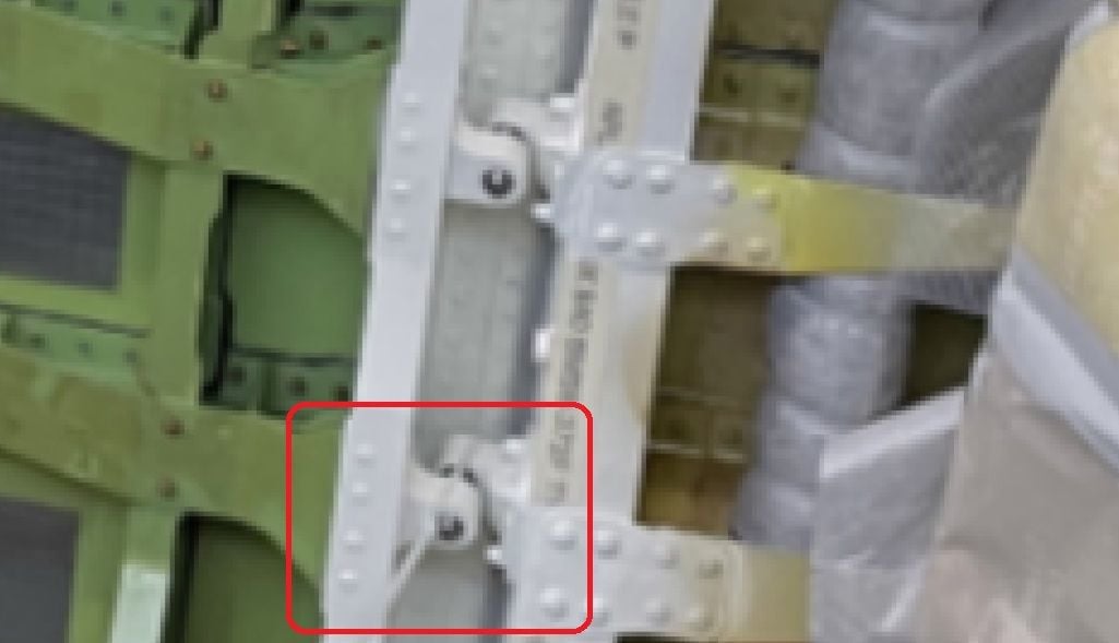
That's the accident aircraft and, if I'm not mistaken, that looks to me (and my source) like a zip tie around one of the stops on the forward edge of the door. If so, that could have been what kept the door in place until either the tie snapped or it worked its way off one or other of the elements of the stop.
I'll admit to being very surprised that there's no reference to it in the NTSB report.
Join Date: May 2010
Location: SOF BG/EU
Age: 63
Posts: 90
Likes: 0
Received 0 Likes
on
0 Posts
Obviously, with four or even two arrestor bolts in place (that is one each on both the forward and aft side), the MED plug would not have been able to move up less than half an inch (sic!) it apparently did to cause the plug to dislodge and depart the aircraft. When indeed nothing in terms of arrestor bolts, the pigtail suggested by DaveReidUK could indeed be an explanation why the plug didn’t depart earlier than on its 152th sector. Bravo pigtail indeed!
“Figure" 14 is from 1 Sept, when the defective rivets were discovered expediently after arrival of the aircraft frame at Renton on the 31st of Aug. “Figure” 16 is from late on 19 Sept, following a second attempt to repair the rivets. The first attempt (the paint over job) was made on 7 Sept. So meanwhile they continued to finish the aircraft.
Don’t forget this aircraft got its pressurisation test on 12 Sept (ref. The Air Current). In all probability still with the arrestor bolts in place, since the plug was only opened by Boeing on 18 Sept at the start of the “real" rivet repair by Spirit (or its contractor(s), according to TAC's sources.
NTSB’s preliminary doesn’t mention anything about a seal change at the time of the “real” rivet repair (as per TAC and "trowawayboeing...").
And as Pinkman rightly notices, neither the does the preliminary dwell on the potentially relevant issue that the plug, according to the L/N written on it (most probably at Spirit), was destined to be installed on another (later) airframe.
Nor does the preliminary mention anything about the fact that the accident aircraft, contrary to other similar "finished" aircraft around the same time, after its factory rollout had been photographed on 23 Sept (four days after the final rivet work and Boeing's acceptance of that) with its MED plugs still firmly tape sealed all around on the outside (as per "Aviation Flights"), suggesting at least some unfinished business in that area (see post 1469).
Some contributors define the drawing on the plug window as graffiti. One could see it rather as the symbol widely used throughout the world to ward off the "evil eye". Interesting to have something superstitious involved in something as rational and technical as building an airplane. And rather ominous in the particular case….
And finally, the following sentence on p. 17 of the preliminary is the ultimate placeholder for determining the non-interaction between Spirit’s SAT and Boeing’s CMES, and why in CMES the "opening" of the plug, contrary to "removing” it, doesn’t trigger a QC, despite both cases require the removal and re-installation of the 4 arrestor bolts:
"The investigation continues to determine what manufacturing documents were used to authorize the opening and closing of the left MED plug during the rivet rework."
A bit of a letdown, isn't it?
Regards
Last edited by D Bru; 12th Feb 2024 at 08:23. Reason: no longer believe in any plug "holding" capacity of panel- and window-trim
Join Date: Jan 2013
Location: Modena, Italy
Age: 76
Posts: 5
Likes: 0
Received 0 Likes
on
0 Posts
How could trim secure the plug door?
Again, the last posts have overlooked the window trim panel contribution to keeping the plug in position and from moving freely upwards, as mentioned by wbclay, repeated by TURIN and again by Loose rivets; not just a singular cable tie!
Any reports of the trim panel being found?
They are normally quite tightly held by various means including velcrow and closing trap strips, possibly a form of 1/4 turn faster; they would slot behind the lower vent panels too.
And I am not suggesting they would resist the decompression loads.
Any reports of the trim panel being found?
They are normally quite tightly held by various means including velcrow and closing trap strips, possibly a form of 1/4 turn faster; they would slot behind the lower vent panels too.
And I am not suggesting they would resist the decompression loads.
I intended to suggest ONLY a possible mechanical interlock between the interior trim and the plastic window frame/trim. I can see no other likely source of friction (or other influence) between the plug door and the interior trim panel.
From the best available photo of interior of the entire plug door (fig. 8, p.10), I see no artifacts (holes, pins, clips, green paint scratches, ...) that suggest attachment between the plug door and the interior trim panel. Perhaps there is a single horizontal Velcro strip on the plug door frame top edge, but it seems too recessed and there's nothing else evident. I thus assumed that the interior panel's only attachment to the airframe (other than the overhead "longitudinal bracket" I hypothesized, and perhaps a similar horizontal structure underneath the trim panel) is to the same vertical ribs that anchor the stop pads, or perhaps structural members even further away from the plug door.
Door Closing
Absolutely true, excellent description, the stop guides and fittings are not crashing into each other every time the door plug is swung open or closed.
People are confusing two different things. The springs CAN be strong enough to support the weight of the door plug, AND the door plug CAN be held at the bottom in the absence of bolts.*
Both can be true, one does not preclude the other.
*by friction of the seals and friction of the interior trim against the plug (TURIN's post #1673), or by a zip tie, or by a loosely placed bolt in the upper aft door guide.
Join Date: Jan 2024
Location: Naples
Posts: 15
Likes: 0
Received 0 Likes
on
0 Posts
some lateral thinking
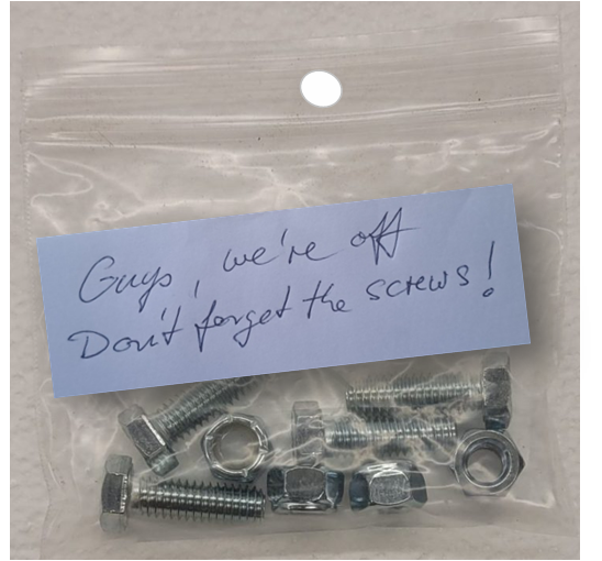
Perhaps we attribute a significance to the zip tie that it doesn't deserve.
Could it be as simple as using it to attach the bag of locking-bolts for the next shift
And then, later on, someone happened to pass by and identified the bolts as an ideal addition for a personal project.
Could it be as simple as using it to attach the bag of locking-bolts for the next shift
And then, later on, someone happened to pass by and identified the bolts as an ideal addition for a personal project.
"Some contributors define the drawing on the plug window as graffiti. One could see it rather as the symbol widely used throughout the world to ward off the "evil eye". Interesting to have something superstitious involved in something as rational and technical as building an airplane. And rather ominous in the particular case…"
It would be detrimental to write on the actual window pane, I took this marker as a reminder that there was a protective film to be removed!
Fig 16 of DCA report and text quite clearly shows the plug in position without at least 3 of the locking bolts, tie wrap or internal trim panel holding it, though assuming the top rear locking bolt was also not fitted at this time it would suggest that the plug can sit quite well unpressurized and only likely some tape on the outer circumference. Assumption the contact with the stops is sufficient to hold the plug against the assist springs at this point of time.
Second magnification zip tie is present.
Last edited by aeromech3; 8th Feb 2024 at 13:18. Reason: tie is present

Join Date: Oct 2017
Location: Munich
Posts: 3
Likes: 0
Received 0 Likes
on
0 Posts
Join Date: Jan 2024
Location: USA
Posts: 10
Likes: 0
Received 0 Likes
on
0 Posts
Disregard. The pin isn't hollow.
Last edited by MZoVrsmg; 8th Feb 2024 at 14:34.
NTSB�s Preliminary Report is so disappointing. We still don�t know which way�s up. Or more specifically do �lift assist springs� exert a force on �MED plug� less or greater than weight of plug?
To latch plug do we lift it up (assisted by springs), align guides with rollers, push plug in and lower it on to rollers? That seems logical to me.
To latch plug do we lift it up (assisted by springs), align guides with rollers, push plug in and lower it on to rollers? That seems logical to me.
Dassault Falcon 900s had a similar system on the main entrance door. Early production aircraft in the EX series had a large counterbalance leaf spring underneath the floor which made it very easy to lift the door up to close it from the outside. You could lift it up with just one hand and the door �felt� like it weighed just a few pounds.
In this case, the spring force was slightly less than the door weight, but only slightly less. You would not want the force to be greater than the door weight or the door would not stay fully �down� when open.
The leaf spring was made of multilayer composite material and was prone to cracking. As time went on, repairing/replacing the springs became a problem because a limited number existed in the spares inventory at Dassult. As a result, they developed an electric lift motor to raise the door. This was the default on later production aircraft, and was made available as a retrofit on earlier aircraft via service bulletin.
Closing the door from the outside without electric power available made it clear that the door was actually quite heavy. Without the counterbalance spring, you need to use both arms and �put your back into it� to lift the door up and close it.
I suspect the springs on the MAX 9 plug door either exactly counterbalance the door weight, or exert slightly less force than the door weight, but wouid make it easy for a maintenance person to lift it off the rollers with little effort.
Join Date: Jan 2024
Location: Naples
Posts: 15
Likes: 0
Received 0 Likes
on
0 Posts
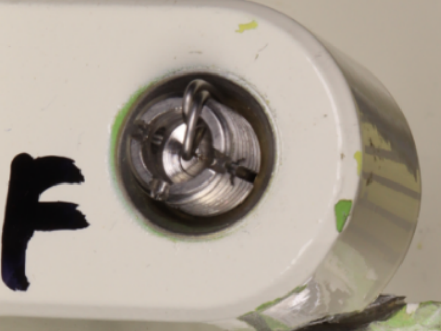
Wrapping the zip tie around the two lugs can hold them togerther within limits, no question .
Your drawing is based on the assumptiom that the stop pad bolt is entirely hollow . This is not the case, please find pic below for your convenience.
The springs may exactly counterbalance the weight of the door so that they exert no relative �lift� force - but would make it easy for one person to move the door upwards by applying a relatively low amount of force with the hands. (Once the restraining bolts are removed).
Dassault Falcon 900s had a similar system on the main entrance door. Early production aircraft in the EX series had a large counterbalance leaf spring underneath the floor which made it very easy to lift the door up to close it from the outside. You could lift it up with just one hand and the door �felt� like it weighed just a few pounds.
In this case, the spring force was slightly less than the door weight, but only slightly less. You would not want the force to be greater than the door weight or the door would not stay fully �down� when open.
The leaf spring was made of multilayer composite material and was prone to cracking. As time went on, repairing/replacing the springs became a problem because a limited number existed in the spares inventory at Dassult. As a result, they developed an electric lift motor to raise the door. This was the default on later production aircraft, and was made available as a retrofit on earlier aircraft via service bulletin.
Closing the door from the outside without electric power available made it clear that the door was actually quite heavy. Without the counterbalance spring, you need to use both arms and �put your back into it� to lift the door up and close it.
I suspect the springs on the MAX 9 plug door either exactly counterbalance the door weight, or exert slightly less force than the door weight, but wouid make it easy for a maintenance person to lift it off the rollers with little effort.
Join Date: Jan 2024
Location: USA
Posts: 10
Likes: 0
Received 0 Likes
on
0 Posts
With the door closed, the spring force would be even higher.
The suggestions that a cable tie would be strong enough to hold the door closed if aided by the interior trim make no sense to me. There is no trim panel fitted in the photo that shows the cable tie.
There should be no reason to adjust the stops to open or close the plug. They would retain the adjusment that was made when the plug was fitted before fuselage delivery. That correct adjustment would allow the plug to move up with no contact between stop pads and stop pins. With stops correctly adjusted I do not believe that the cable tie could hold the plug down and maintain the shape shown in the photo.
I think the idea that the tie supported a tag and/or parts bag is more likely. The argument that it's not an ideal place for a tag are equally applicable to the position if used to hold the plug closed.
My money is still on a temporary pin in the upper aft guide track. That is the location most easy to reach after the plug has been pulled down and is held in place with the right hand.
Join Date: Jan 2024
Location: USA
Posts: 10
Likes: 0
Received 0 Likes
on
0 Posts
I've never seen a setup like that before. Tried looking for pictures, but my google skills fell short.
Regarding the placement of the zip tie, I guess the white spot in the photo at 12" on the threaded pin is a reflection, and not the zip tie disappearing into the fastener as I'd assumed.
Maybe the zip tie is in a "figure 8" arrangement around the two lugs?
Join Date: Jan 2024
Location: Naples
Posts: 15
Likes: 0
Received 0 Likes
on
0 Posts
Within the boundaries of their engineering skills they opted for the " figure 0 " configuration, the worst in terms of stress for the zip-tie.
With the "figure 8" configuration put in place, although being a nightmare for tightening, there was a fair chance that this entire thread would not exist and was yet to emerge in the future.