


Alaska Airlines 737-900 MAX loses a door in-flight out of PDX

Join Date: Jan 2024
Location: USA
Posts: 10
Likes: 0
Received 0 Likes
on
0 Posts
Regarding the zip tie:
Given that it's around both the plug and fuselage structures, it could not have held the "bag of missing bolts" that's been speculated about. Such a bag would have been secured at the time the plug was removed, prior to rivet re-work. This zip tie could only have been installed after the plug was "closed".
Now, it could have been installed for after plug closure for bag/flag reasons (suggesting that there's something in that top left hole), but again, it's around both parts. Why would someone have put the effort to do that in the bag/flag scenario?
Now, it could have been installed for after plug closure for bag/flag reasons (suggesting that there's something in that top left hole), but again, it's around both parts. Why would someone have put the effort to do that in the bag/flag scenario?


Instead we see the entire inner wall of the guide fitting sheared away including the relatively deep section of the flange where it turns through 90 degrees, all this by a 3/4" ? dia pin. Maybe I'm misunderstanding how the failure occured, any comments?

Join Date: Jan 2024
Location: Scotland
Posts: 52
Likes: 0
Received 0 Likes
on
0 Posts
Because it was a ductile fracture. What you are thinking of is a brittle fracture. Also, the guide failed as the door plug was moving upwards so the point of stress was movink down the guide.
Anyone else puzzled by the fracture surfaces and mode of failure? As the unrestrained plug door finally moved upwards that last bit to the point where the stop pad fittings were no longer in line with the stop pins a sudden large force was applied to the inside of the guide fitting's inner wall. This force was initially a single line contact, ie between the side of a cylinder (the pin), and the flat surface of the guide. At this point the inner guide flange is only seeing load from this line contact, and what surprises me is the the flange didn't fail across its width at this point, then followed by tearing of the flange wall sideways, just enough to let the pin through?
Instead we see the entire inner wall of the guide fitting sheared away including the relatively deep section of the flange where it turns through 90 degrees, all this by a 3/4" ? dia pin. Maybe I'm misunderstanding how the failure occured, any comments?
Instead we see the entire inner wall of the guide fitting sheared away including the relatively deep section of the flange where it turns through 90 degrees, all this by a 3/4" ? dia pin. Maybe I'm misunderstanding how the failure occured, any comments?
So, how does the rest get sheared?
There is a tipping point.
Imagine, if the side wall was very, very short, then the wall would not have enough tensile strength to overcome the shear and it would punch out or burst.
If the side wall was very deep as is the mating roller, the roller starts shearing the wall at the contact and begins moving that area outward. The rest of the roller is pressing into the wall. The wall, in turn, produces horizontal tension, (think rubber band) and the only place that tension can be resisted is at the same plane as the initial shearing is taking place because the tension is uniform as it conforms to the roller.
In this case it appears the wall was tall enough to take that tension load that came from the geometry change to tear the rest of the wall loose.
Notice that the rip went farther up than down - because there was a larger section of material at the bottom than the top.
In typical metals the shear strength is about 50% of the tensile strength, so if the shearing section is the same as the tensile area, tension will promote shear failure. In this case the tensile area is far larger than the shear area, tipping the scale even farther to shear.
When was it lifted..?
Some will still be wondering when the Plug was lifted out of alignment. I thought Jolts from running over Centre Line Lights could be sufficient, but it was pointed out that my other suggestion of Turbulence at 16,000 ft would not be possible, as the Plug had the high Pressure Differential restricting its movement.
However I seem to remember that the cabin starts to pressurise even whilst Taxiing, for some reason or other. So the initial lift could have occurred on the climb-out, if they encountered turbulence, before the Cabin Differential Pressure rose too much.
However I seem to remember that the cabin starts to pressurise even whilst Taxiing, for some reason or other. So the initial lift could have occurred on the climb-out, if they encountered turbulence, before the Cabin Differential Pressure rose too much.
Join Date: May 2011
Location: U.S.
Posts: 84
Likes: 0
Received 0 Likes
on
0 Posts
This is only a lawsuit, not a solid, objective source, but the question of the unoccupied seats 26A and 26B may not be closed yet.
It has now been widely reported that a recently filed lawsuit reports a whistling sound was heard by passengers on previous flights.
One source which includes the lawsuit is at the link:
KGW News
Quoting the lawsuit:
7.4 Upon information and belief, there was a whistling sound coming from the vicinity of the door plug on a previous flight of the subject plane.
7.5 Passengers apparently noticed the whistling sound and brought it to the attention of flight attendants who reportedly informed the pilot or first officer.
7.6 After the pilot checked cockpit instruments, which purportedly read normal, no further action was taken. Further discovery on this issue is necessary.
Psychophysiological entity
SRMman,
Indeed yes. I was going to post on it, but already post too much of my 'lateral thinking'. :-(
Troubled by the woefully short roller pin, I wondered if the complex patterning of the split surface has a story to tell. At its lowest, there's a circular pattern which might imply the end of the roller/pin chattered on the split's surface. All this could have been done quickly, but it makes me think it might display frenzied oscillations before finally letting the plug escape.
Whatever the minutia, there is little doubt the roller could abut the edge of a g-lock bolt at only half the latter's diameter. That's assuming one was there of course.
Anyone else puzzled by the fracture surfaces and mode of failure?
Troubled by the woefully short roller pin, I wondered if the complex patterning of the split surface has a story to tell. At its lowest, there's a circular pattern which might imply the end of the roller/pin chattered on the split's surface. All this could have been done quickly, but it makes me think it might display frenzied oscillations before finally letting the plug escape.
Whatever the minutia, there is little doubt the roller could abut the edge of a g-lock bolt at only half the latter's diameter. That's assuming one was there of course.
Join Date: Feb 2008
Location: Apple Maggot Quarantine Area
Age: 47
Posts: 100
Likes: 0
Received 0 Likes
on
0 Posts
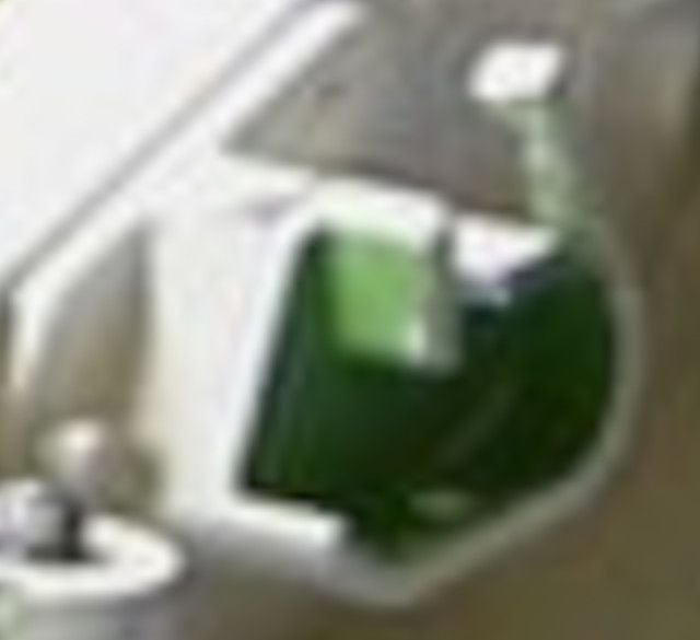
It's an air duct with insulation on top. You can see the SCAT tubing coming out of the insulation toward the bottom.
Some will still be wondering when the Plug was lifted out of alignment. I thought Jolts from running over Centre Line Lights could be sufficient, but it was pointed out that my other suggestion of Turbulence at 16,000 ft would not be possible, as the Plug had the high Pressure Differential restricting its movement.
However I seem to remember that the cabin starts to pressurise even whilst Taxiing, for some reason or other. So the initial lift could have occurred on the climb-out, if they encountered turbulence, before the Cabin Differential Pressure rose too much.
However I seem to remember that the cabin starts to pressurise even whilst Taxiing, for some reason or other. So the initial lift could have occurred on the climb-out, if they encountered turbulence, before the Cabin Differential Pressure rose too much.
Join Date: Jun 2009
Location: Montreal
Age: 65
Posts: 41
Likes: 0
Received 0 Likes
on
0 Posts
Something I noticed in the picture in post 1632 is that the failure mode on the fwd guide bracket seems to be different. Here is a detail from the picture:
So it appears the lower block of material stayed attached to the fwd fitting. If I may attempt a reconstruction of what figure 10 would look like for the fwd fitting, it might be like this
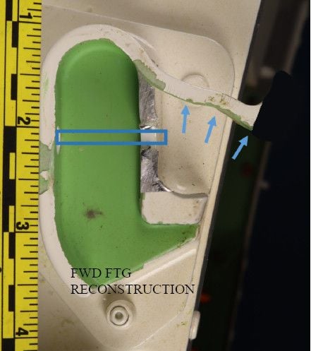
Apologies if I'm not seeing things right. So the fwd failure is *kind* of a combined punch-through/tear off failure more in line with what some people expected to see. As to why they might be different, it could come down to statistical variation in material properties, and slight differences in positioning of the roller pin at departure of the door.
Another observation, someone drew a v-shaped fleche with a sharpie on the fracture surface (a no-no in fracture analysis but anyway...) which I guess is the contact point of the roller at failure.
So it appears the lower block of material stayed attached to the fwd fitting. If I may attempt a reconstruction of what figure 10 would look like for the fwd fitting, it might be like this
Apologies if I'm not seeing things right. So the fwd failure is *kind* of a combined punch-through/tear off failure more in line with what some people expected to see. As to why they might be different, it could come down to statistical variation in material properties, and slight differences in positioning of the roller pin at departure of the door.
Another observation, someone drew a v-shaped fleche with a sharpie on the fracture surface (a no-no in fracture analysis but anyway...) which I guess is the contact point of the roller at failure.
Last edited by incompleteness; 10th Feb 2024 at 02:03. Reason: spelling
I think that V is the boundary between shear under compression and shear under tension, not sharpie.
Material inside the V is being piled up from being pushed and outside the V is being stretched by being pulled apart.
Material inside the V is being piled up from being pushed and outside the V is being stretched by being pulled apart.
Join Date: Jun 2009
Location: Montreal
Age: 65
Posts: 41
Likes: 0
Received 0 Likes
on
0 Posts
That is absoultely what I thought too until I zoomed in on the upper line and saw it seems to extend onto the painted surface of the fastener hole, so it looks like its been drawn on. It could be someone's attempt at showing the boundary between principal-tension and principal-compression as you describe.
It's looking at half a hole; there's no painted hole surface along the break that faces the camera. There is a chunk missing from the hole edge as the unsupported edge gave way.
They have photo editing software, so there's no need to mark anything on the fracture surface.
The lighting is from bottom right with a small softbox, as seen by the soft shadow from the bottom rivet.
More looking at it.
Opposite the tear the paint on the slot is beaten to heck. Perhaps that is where the roller or part of the roller bracket has been for a while, with the stops on the teetering edge of the mating fitting, allowing a little more room to allow the door to move into the fuselage. This fits with the cable tie - the tie would increase tension as the door moved up, arresting the movement, until the tie finally gave.
It is a shearing failure. The roller cannot punch a slot outward as the wall of the slot is only supported on one side. The only initial load that can be applied is at the end of the roller; the rest of the vertical wall of the slot has nothing but its attachment to the base to resist load; sure, a small bending resistance, but it's far easier to bend than shear which means the load from bending is far smaller.
So, how does the rest get sheared?
There is a tipping point.
Imagine, if the side wall was very, very short, then the wall would not have enough tensile strength to overcome the shear and it would punch out or burst.
If the side wall was very deep as is the mating roller, the roller starts shearing the wall at the contact and begins moving that area outward. The rest of the roller is pressing into the wall. The wall, in turn, produces horizontal tension, (think rubber band) and the only place that tension can be resisted is at the same plane as the initial shearing is taking place because the tension is uniform as it conforms to the roller.
In this case it appears the wall was tall enough to take that tension load that came from the geometry change to tear the rest of the wall loose.
Notice that the rip went farther up than down - because there was a larger section of material at the bottom than the top.
In typical metals the shear strength is about 50% of the tensile strength, so if the shearing section is the same as the tensile area, tension will promote shear failure. In this case the tensile area is far larger than the shear area, tipping the scale even farther to shear.
Thank you! As I looked at the photograph I'd conveniently forgotten the very significant resistive reaction at the only significant point of load application, the end of the roller! As you say the initial failure in shear would have been here, then continued web shearing either side of this point. Once the full width of the roller had passed through the web then it was just a matter of which mode of failure, tension or shear, would prevail - and it continued to be shear.
Join Date: Jan 2024
Location: Scotland
Posts: 52
Likes: 0
Received 0 Likes
on
0 Posts
Endless speculation about the failure mode of the guide is pointless as it was not designed to hold the door in place. The guide and roller are unstressed in flight. Similarly, the roller is not too short!
But this raises an important question: was the door plug literally hanging by a thread for the last couple of flights? If so, the theory that a higher differential pressure would have prevented the door plug from exiting the aircraft at higher altitudes (because of increased forces against the stop pads) may be inapplicable. Would the structure surrounding the door plug have survived a sudden pressure equalization if the door plug had blown at, say, FL410?
Last edited by xetroV; 11th Feb 2024 at 18:32.
With the door in place the structure around the door sees the highest loads possible when pressurized. The door leaving removes the load applied by the door to the surroundings. As to magazines, socks, shirts, and cell phones - anything not in the load path - those would have had a somewhat higher load, but I'm not sure if choke flow could happen, putting a ceiling on the flow rate. The cockpit door might have slammed a bit harder, but it fails at a given delta-P which is only the difference between the cockpit and the cabin and not the cabin and the outside air; so maybe that delta-P is reached milliseconds earlier.