


Concorde question

Fuel penalty for speed limit?
That 250 kt limit had a truly startling effect on climb rate. Compared with an unrestricted climb, how much would that limit cost in fuel?

Join Date: Dec 2010
Location: Europe
Age: 88
Posts: 290
Likes: 0
Received 0 Likes
on
0 Posts
Well it took a long time, but Dudley eventually came up trumps!
 ">
">
If anyone wants more, the source is an AGARD CP 260 by Cazenove and Ivroas ( but I have not been able to access the only URL that comes up on Google!)
CliveL
">If anyone wants more, the source is an AGARD CP 260 by Cazenove and Ivroas ( but I have not been able to access the only URL that comes up on Google!)
CliveL
Join Date: Dec 2010
Location: Europe
Age: 88
Posts: 290
Likes: 0
Received 0 Likes
on
0 Posts
Thanks for that much better picture Bellerephon.
I have a bit more information now, although my French is very rusty so I may not have it all correct - CJ can probably correct me if necessary.
They did 8 flights over 10 hrs, preceded by about 30 simulator 'flights'. Most of the flight testing was looking at low speed behaviour, since that was where they expected to see most gains on Concorde, and where the most problems might be expected, but they did go up to 2.04M. The primary advantage was seen to be the possibility of using very aft CGs for takeoff to reduce trim drag - they flight tested as far back as 56% at around 0.4M (no consideration of limits from U/C location of course for this sort of testing). In addition they were predicting a weight saving of around half a tonne.
The simulator work sorted out the basic laws, where they tested a pure pitch rate feedback and a C* law with load factor and pitch rate terms. The pilots preferred the latter (which became in time the basis for the A320 laws).
The simulator was also used to establish the best ergonomics (movement and force harmonisation) of the sidestick.
The 'blue' electrical signalling system for elevons was replaced by the digital control and sidestick arrangement, keeping the 'green' signalling as a safety backup. Normal rudder control system was retained, as well as the mechanical backup.
In the general arrangement of the digital control system one can see clearly the genesis of the A320 design - two computers with the software written by separate teams etc.
Pilot reaction seems to have been very favourable, the aircraft being somewhat easier to fly than the basic Concorde (which was already pretty good ....).
In particular the paper suggests that the precision with which the aircraft could be positioned was much improved.
Stick force per 'g' was pretty much the same throughout the speed range at about 7daN/g, whereas on Concorde it varies from 20 to 40 daN/g - but on a sidestick rather than a control column of course.
One problem that did show up, although not peculiar to Concorde, was the sensitivity of these systems to structural response, particularly during ground roll.
Not contained in the report, but in a side letter from Dudley, is a remark that the guy most responsible for the development of the Concorde basic system and later in charge of the Airbus system thought that these Concorde experiments were the key to the success of the A320.
'Nuff said!
CliveL
Thread Starter
Never get tired of this thread !
Very interesting about the sidestick, was the installation and testing purely for research / experimentation purposes or was it seriously contemplated for use in production Aircraft ?
If so, why was it decided against ?!
Very interesting about the sidestick, was the installation and testing purely for research / experimentation purposes or was it seriously contemplated for use in production Aircraft ?
If so, why was it decided against ?!
Join Date: Dec 2010
Location: Europe
Age: 88
Posts: 290
Likes: 0
Received 0 Likes
on
0 Posts
Basically an R&D exercise I think, funded by the French government in the same way as NASA might fund as similar research project.
It was done at just about the time that Concorde development was being abandoned, but had anyone seriously contemplated a Concorde 2 then ths would certainly have figured in the design.
It was done at just about the time that Concorde development was being abandoned, but had anyone seriously contemplated a Concorde 2 then ths would certainly have figured in the design.
Join Date: Jan 2008
Location: FL 600. West of Mongolia
Posts: 463
Likes: 0
Received 0 Likes
on
0 Posts
A Side Sticky Subject
As I recall, they referred to this research project as a CCV (Controlled Configured Vehicle) design study. It would be great if we could get this confirmed, but they talked about subsonic drag reductions of 10 to 15% by flying (not taking off!!) with a far more aft CG than the norm. The 'system' I seem to remember, as a result naturally commanded some down elevon, which increased lift. As the aircraft could then fly with less alpha, I guess this is where the drag reduction comes from. (Clive, I wonder if you could find out through one of your contacts if this was true?).
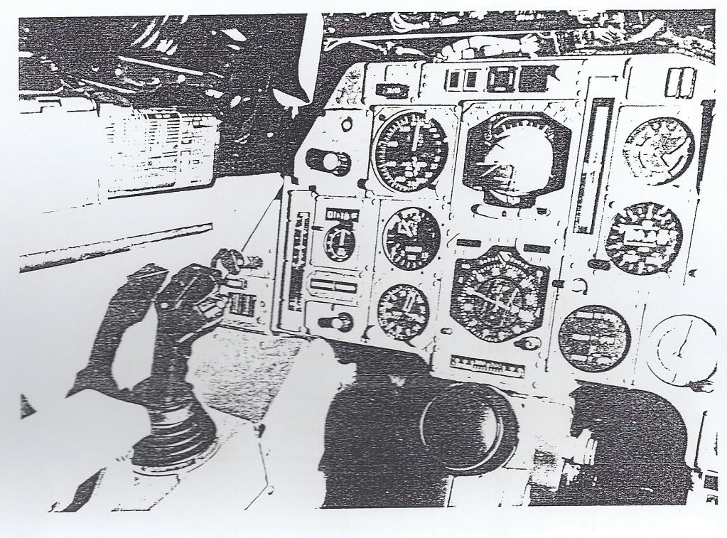
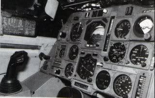
I'd still personally like to know how the sidestick was integrated into the flying control system, I've been thinking and can not now believe that sidestick inputs could be simply input to the flying control system 'at resolver level'. Remember that the concept of the FBW system on Concorde was that resolvers were utilised as simple 4 wire synchros, and the pitch and roll axis utilised a CX/CDX/CT chain, which produced the error signal to the ESA's in the Autostab computers. Using a sidestick completely breaks up the chain, and my guess is that a seperate digital unit contained the flight rules which were summed against PFCU CT position and sidestick input would have been necessary. It is possible then that an analog output from this 'box' could be fed to the Autostab Computer ESAs and hence drive the elevons. I'm probably completely wrong, but I'd surely still love to know the truth. As you say Clive, ideal stuff for Concorde 2.
Best regards
Dude
Last edited by M2dude; 21st Jun 2011 at 17:53. Reason: A fine wine may improve with age... my spelling however doesn't
Join Date: Dec 2010
Location: Europe
Age: 88
Posts: 290
Likes: 0
Received 0 Likes
on
0 Posts
Don't need no contacts Dude. The drag reduction came simply from flying at a lower AoA when trimmed at an aft CG. Less 'up' elevon, which is similar but not the same as 'down elevon' in an absolute sense, so less adverse elevon lift and work the wing to a lower AoA in consequence. Just an extension of the basic Concorde certification with a 'point' TO CG really.
They were certainly looking to study control laws that allowed flight at very aft CGs to increase aircraft performance, so yes, this was a CCV exercise, but they were also seeking experience with digital control and system architectures that could be transferred to other active control applications.
The 'sidestick' arrangement was virtually a complete A320 style arrangement using two computers and digital signalling throughout. For just 10 hrs they wouldn't need anything more complicated than a 'panic switch' to return control to the standard Concorde green system that was still there and available.
Clive

Join Date: Dec 2010
Location: Europe
Age: 88
Posts: 290
Likes: 0
Received 0 Likes
on
0 Posts
They weren't looking for cruise drag reductions; just takeoff climb improvements which would have required genuine relaxed stability - CGs back at the aerodynamic centre etc.
This entailed introducing artificial stability terms that would have been difficult in a purely analogue system such as the basic Concorde controls, so they decided to go digital.
Sidestick or conventional control column doesn't come into that of course - see Boeing vs AI FBW systems; but no doubt the French government saw the opportunity to get two for the price of one .....
CliveL

Join Date: Dec 2010
Location: New York & California
Posts: 414
Likes: 0
Received 0 Likes
on
0 Posts
NW1
I assume in the US then you were restricted to 250 kts below 10,000 feet just like all other aircraft?
Why higher speed? That have to do with shockwaves and the resulting pressure distribution differences?
No, I meant the airspeed you'd be flying at while climbing (post takeoff)
Wow, that's pretty bad. You'd figure with a T/W ratio of around 0.40 you'd do far better than most other aircraft.
Were you allowed to get over 250 below 10,000 feet in the US, or UK? Regardless, what rate of climb would you get at that speed?
408,000 pounds?
It was expressed in the flight manual as "Lowest Authorised" speed, Vla, and didn't depend on weight. 0-15,000' Vla=V2 or Vref as appropriate, 15,000'-41,000' Vla=250kias
41,000'-60,000' Vla=300kias
I'm guessing you mean rate of climb rather than IAS?
if restricted to 250kts (way below min drag) you'd get pretty poor rates of climb - about 1000fpm if you were lucky
and IIRC - you'd quickly want to lower the nose, just barely climb and get her up to 400kts when she'd really fly...
most transatlantic takeoffs were at MTOW - around 185 tonnes
Join Date: Dec 2010
Location: Europe
Age: 88
Posts: 290
Likes: 0
Received 0 Likes
on
0 Posts
Quote:
if restricted to 250kts (way below min drag) you'd get pretty poor rates of climb - about 1000fpm if you were lucky
Wow, that's pretty bad. You'd figure with a T/W ratio of around 0.40 you'd do far better than most other aircraft.
if restricted to 250kts (way below min drag) you'd get pretty poor rates of climb - about 1000fpm if you were lucky
Wow, that's pretty bad. You'd figure with a T/W ratio of around 0.40 you'd do far better than most other aircraft.
Join Date: Dec 2010
Location: New York & California
Posts: 414
Likes: 0
Received 0 Likes
on
0 Posts
CliveL
Then what does 250 kts, 19-degrees of climb, afterburners engaged produce?
Brian Calvert quotes 250 kts/2000ft/1000fpm/12deg attitude/reduced thrust for this.
Join Date: Nov 2001
Location: UK
Posts: 171
Likes: 0
Received 0 Likes
on
0 Posts
<<I'm guessing you mean rate of climb rather than IAS? >>
<<No, I meant the airspeed you'd be flying at while climbing (post takeoff)>>
OK, then the answer to your Q's:
Also what was the typical climb speed
- At lift-off? About 200kts
- Once 240 kts is achieved? 240kts
- At minimum maneuvering speed at typical takeoff weight? Vla after takeoff was V2 until 15,000'. I.E. about 220kts
- At MTOGW? V2 didn't vary much by weight
Out of JFK we flew at Vmo once further than 12nms from the coast. Vmo=400kts IAS at low level.
Out of LHR overland the IAS restriction was 300kts until past the speed limit point early in the SID - much less draggy than 250kts and hence better climb rates. But you'd quickly be released to get to 400kts (barder's pole) where it was designed to be flown.
<<Why higher speed? That have to do with shockwaves and the resulting pressure distribution differences?>>
The flight envelope was bigger and more complex than subsonic types: it was developed in flight test and probably had many considerations involved. I think someone posted it earlier in this thread in graphical form (from the flight manual) if you want to see it. In practice, you had to be aware of three basic parameters - IAS, Mach and CG position (the CG "corridor"). Once understood, it wasn't that difficult to keep up with it...and the IAS and Machmeters had barber's poles handily programmed to show the limiting values (including, cleverly, max temp on the nose Tmo=127 degrees celcius).
Regarding climb rates - best ROC was at 400kts (MTOW) or 380kts (MLW). As speed reduced below that, drag increased and ROC reduced. At MTOW and 400kts you'd get about 4000fpm max dry power. At 250kts it was all noise and very few feet per minute - after noise abate procedures you had to lower the nose, just barely climb, and get IAS up toward min drag as soon as possible. With an engine failed go for 300kts minimum - Vmo as soon as you can.
<<shockwaves and the resulting pressure distribution differences>>
You had to avoid the "transonic" region due to these effects: maximum subsonic cruise was 0.95M due to the auto-stabilised flying controls become over-active as shockwaves started to "dance" around the airframe (usually asymmetrically). This calmed down by about 1.3M in the acceleration (when the intake ramps started to do their thing). To accelerate to 2.0M you needed reheat until 1.7M so you didn't hang around between 0.95M and 1.7M. FL260 was best for subsonic cruise because at that level 400kts IAS = 0.95M...
Last edited by NW1; 24th Jun 2011 at 08:09.
Join Date: Jul 2005
Location: Ask my wife, mother or employer
Posts: 131
Likes: 0
Received 0 Likes
on
0 Posts
Per Person Operating Costs
At the time Concorde stopped flying was she making a profit?
My question however is this:
If we assume that the Concorde operation is not for profit, what should have been the cost of a ticket per person in 2003 to have broken even.
If she was still in service today, given airframe and engine servicing, fuel prices etc... what would have been the cost today of a ticket?
Join Date: Mar 2000
Location: UK
Posts: 5,197
Likes: 0
Received 0 Likes
on
0 Posts
Heads up for Concorde enthusiasts -
http://www.pprune.org/aviation-histo...rde-pilot.html
Biography just published.
http://www.pprune.org/aviation-histo...rde-pilot.html
Biography just published.