


Concorde question


Join Date: Jan 2005
Location: France
Posts: 2,315
Likes: 0
Received 0 Likes
on
0 Posts
CliveL,
Thanks for the picture, saves me a thousand scribbles.
And it also shows my mistaek... rib 12 was only inboard.
The outer wing did not have a "rib 12", it was the upper and lower edges of the skin that had their own "bath tubs".
CJ
Thanks for the picture, saves me a thousand scribbles.
And it also shows my mistaek... rib 12 was only inboard.
The outer wing did not have a "rib 12", it was the upper and lower edges of the skin that had their own "bath tubs".
CJ
Join Date: Jan 2008
Location: FL 600. West of Mongolia
Posts: 463
Likes: 0
Received 0 Likes
on
0 Posts
CliveL
The dual pressurisation systems each had two discharge valves, one just aft of the nose undercarriage and the other at the rear of the aircraft. The forward valves would carry away the electronics rack discharge air, where the aft would vent the underfloor area. There was no common discharge point Clive, no. The #2 system forward valve would just throw the air overboard, without the sophisticated 'nozzling' of the #1 system. So I guess we have to go figure just how useful the thrust recuperation system was, but I personally think that EXWOK got it right.
ChristiaanJ
The stiffenersd did not go over the bathtub joints my friend, , they were inboard.
Mike-Bracknell
Unfortunately Mike your photo is a little too far outboard to show them. We need to go a little more inboard and slightly further aft. I've been through my photos and can't yet find one. (Honest CliveJ, it is the truth, they DO exist  ).
).
A very happy Christmas to everyone here; Personally I am working right through Christmas AND New Year (darned aeroplanes)
Dude
Dude, Do you know how the #2 system was exhausted if it wasn't through another thrust recovery nozzle? We were never going to throw away 600 lbf thrust every other flight - not on Concorde where we sweated blood to get the parasitic drag down!
Any chance that there was a common discharge point even if the two packs were used alternately?
Any chance that there was a common discharge point even if the two packs were used alternately?
ChristiaanJ
Any chance of a pic or a drawing, M2dude?
It seems almost impossible to me that it was 'something' between inner and outer wing, since it would have had to 'jump' over the bathtub covers.
It seems almost impossible to me that it was 'something' between inner and outer wing, since it would have had to 'jump' over the bathtub covers.
Mike-Bracknell
Since a picture's worth a thousand words, if you guys would like to point to the strengthening straps/spars/thingies on this?
).A very happy Christmas to everyone here; Personally I am working right through Christmas AND New Year (darned aeroplanes)
Dude
Join Date: Dec 2010
Location: Europe
Age: 88
Posts: 290
Likes: 0
Received 0 Likes
on
0 Posts
Unfortunately Mike your photo is a little too far outboard to show them. We need to go a little more inboard and slightly further aft. I've been through my photos and can't yet find one. (Honest CliveJ, it is the truth, they DO exist
Happy Christmas to all
CliveL
Join Date: Jan 2008
Location: Bracknell, Berks, UK
Age: 52
Posts: 1,133
Likes: 0
Received 0 Likes
on
0 Posts

Join Date: Dec 2010
Location: Europe
Age: 88
Posts: 290
Likes: 0
Received 0 Likes
on
0 Posts
Sorry to be picky Mike, but didn't Brit 312 say the cracks were only found on BA aircraft? So maybe (probably) AF never fitted the straps.
CliveL
On the other hand, if we ignore Dude's instruction to go inboard and aft, then there could be spanwise straps ahead of/behind the 'F' of the registration out past the hyphen. Best leave it to those who know I think!
CliveL
On the other hand, if we ignore Dude's instruction to go inboard and aft, then there could be spanwise straps ahead of/behind the 'F' of the registration out past the hyphen. Best leave it to those who know I think!
Last edited by CliveL; 24th Dec 2010 at 11:28. Reason: wrong name
Join Date: May 2002
Location: UK
Posts: 140
Likes: 0
Received 0 Likes
on
0 Posts
Mike,
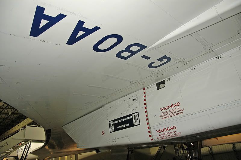
On your original photo you can see perhaps 5 span wise smudges just forward of the dotted red line on the engine. On your second photo you can see them again with three just forward of the registration letters. The problem is that the aircraft in the photos are too clean and so they show up less.
These straps were quite neatly done but for Concorde they were rather agricultural. As far as I remember only BA aircraft suffered this problem for the reasons stated before, but I am not surprised to see that Air france aircraft were also modified.
Join Date: Dec 2010
Location: Europe
Age: 88
Posts: 290
Likes: 0
Received 0 Likes
on
0 Posts
 Christian asked if there was an aerodynamicist in the house - I guess that would be me!
The original question was whether there was any vortex activity in subsonic cruise, but the discussion went on to ask about designing for subsonic drag I think.
The answer to the first bit is that the vortex flow started in a gentle manner from about 6 or 7 deg AoA and got steadily stronger. Depending on the chosen cruise speed and the aircraft weight, the subsonic cruise AoA would have been in the region of 4.5 to 5 degrees, i.e. below any significant vortex development. 6/7 deg would correspond to something in the range 250 to 280 kts probably (I haven't done the sums)
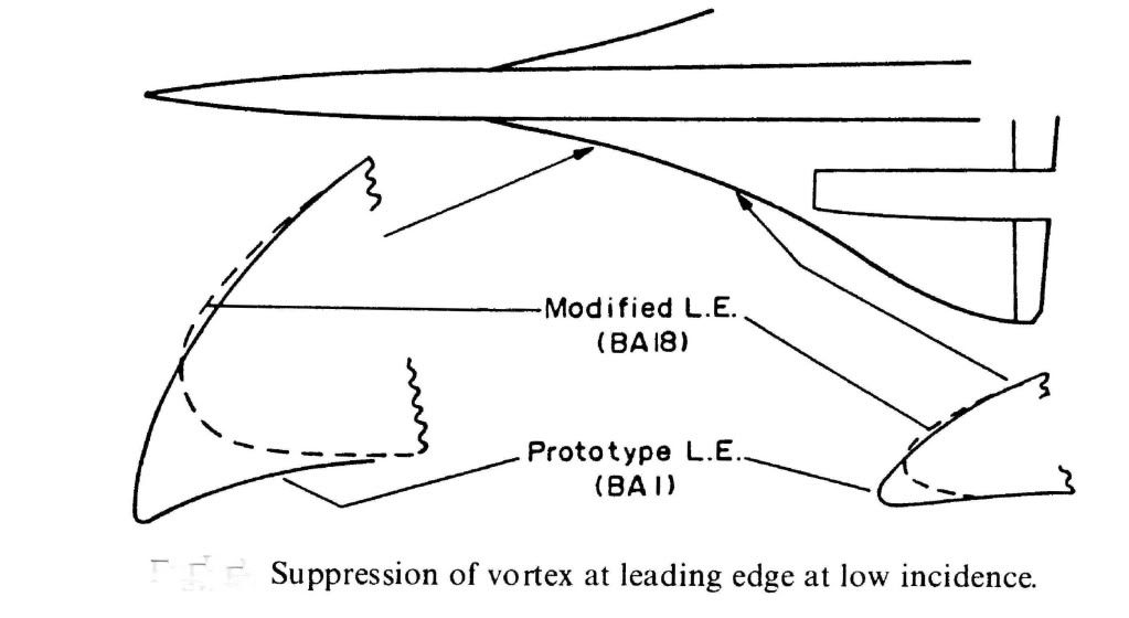
What we were trying to do for subsonic cruise was to have what is known in the trade as 'leading edge suction' acting on a nice bit of forward facing area so that it tried to drag the aircraft forwards as it were. As you can see from the diagram the prototype aircraft had a much more cambered LE so that both suction and forward facing area were very reasonable. This prototype shape was nicely rounded so that LE separation and top surface vortex generation started at a higher AoA than on the production aircraft. Unfortunately this shape, which featured a rather sharp LE on the undersurface, generated a vortex on the undersurface of the wing in supersonic flight and low AoA (near zero 'g'). This vortex got into the intake and caused the engine to surge, so we had to redesign the LE ahead of the intakes as shown. This cost us a little subsonic drag, so you can see from the diagram what you need to do to keep subsonic cruise drag down.
Hope this answers the questions
CliveL
Join Date: Aug 2007
Location: Just west of the North Sea
Age: 69
Posts: 48
Likes: 0
Received 0 Likes
on
0 Posts
Re: stiffeners. This is as close as I can match to the area in question from pics in my collection, no further aft view from this angle unfortunately. Alpha Alpha at East Fortune.
Join Date: Feb 2009
Location: Jungles of SW London
Age: 77
Posts: 354
Likes: 0
Received 0 Likes
on
0 Posts
Happy memories? I'm not sure.
M2Dude wrote:
I haven't needed to read a diagram like that in .... a whole grown up persons lifetime!  AND gates and OR gates, 'Op Amps' and an Exclusive OR, if I'm not mistaken?
Thanks Dude, that really puts texture to cold facts. While you are all taking the trouble to explain a hundred small elements of Concorde's make up, I'm sure many of the readers hooked on this thread will be blinking back tears of insipient brain damage at some of the control logic you have all spoken about.
Certainly it sounds, from time to time, that there were a million little black boxes dotted all over her airframe. I suspect however, that many of the 'terms' and 'laws' spoken about are simply a gate or two, perhaps an op' amp, placed in a larger circuit that modulates the output of that board, thus creating the law or term.
I know you have answered my original question about calibrating all these circuits, but nothing I've seen here yet has reduced my frank admiration for the guys (and girls?) who designed the electronics for Concorde. It required true creativity and instinctive engineering that I doubt still exists. Digital control is a hell of a lot easier than Analogue - in my humble opinion.
Seasons greetings to everyone on this thread, especially to our (growing - welcome Clive) band of Concorde experts.
Roger.
I hope the enclosed diagram helps to put it all in place.
Best Regards
Best Regards
AND gates and OR gates, 'Op Amps' and an Exclusive OR, if I'm not mistaken? Thanks Dude, that really puts texture to cold facts. While you are all taking the trouble to explain a hundred small elements of Concorde's make up, I'm sure many of the readers hooked on this thread will be blinking back tears of insipient brain damage at some of the control logic you have all spoken about.
Certainly it sounds, from time to time, that there were a million little black boxes dotted all over her airframe. I suspect however, that many of the 'terms' and 'laws' spoken about are simply a gate or two, perhaps an op' amp, placed in a larger circuit that modulates the output of that board, thus creating the law or term.
I know you have answered my original question about calibrating all these circuits, but nothing I've seen here yet has reduced my frank admiration for the guys (and girls?) who designed the electronics for Concorde. It required true creativity and instinctive engineering that I doubt still exists. Digital control is a hell of a lot easier than Analogue - in my humble opinion.
Seasons greetings to everyone on this thread, especially to our (growing - welcome Clive
) band of Concorde experts.Roger.
Join Date: Nov 2010
Location: Beijing
Age: 30
Posts: 43
Likes: 0
Received 0 Likes
on
0 Posts
Thanks again for a great pics and great explanation.
I'm was wondering that, according to the manual and some document said
that the vortex lift start to form on wing tip first. Why's that happened?
Why not the root of the wing first?
Is it cause by the local wing tip vortex push the air causing more upwash
and hence more effective AoA causing it to reach the stall AoA first is that right?
Also, does the wing vortex on the Concorde has an influence or the effect on
the rudder?
Thanks for your reply.
Best regards
Join Date: Jan 2008
Location: Bracknell, Berks, UK
Age: 52
Posts: 1,133
Likes: 0
Received 0 Likes
on
0 Posts
Trust me, i'm definitely just here for the ride (so to speak) and quickly defer to you and the others who definitely know!
The AF pic was the best I could do, but i'm glad I didn't mess up too bad to miss out the bits in question for a second time!
Merry Xmas to you and to everyone else who's kept the SLF like me informed and amused for months on this thread.
The AF pic was the best I could do, but i'm glad I didn't mess up too bad to miss out the bits in question for a second time!
Merry Xmas to you and to everyone else who's kept the SLF like me informed and amused for months on this thread.
Join Date: Jan 2005
Location: France
Posts: 2,315
Likes: 0
Received 0 Likes
on
0 Posts
M2dude will have to confirm that the 'lateral stiffeners' he is thinking of are indeed the very roughly 2' long and 5" strips at the location of each spar just outboard of the engine, that are very clearly visible on Coffin Dodger's photo of 'AA.
If so, they are indeed shown in the structural repair manual and listed as 'doublers'. There are ten of those, from spar 62 to spar 71.
Reading "between the lines", the modification dates from about 1978, and was applied by successive service bulletins to both the BA and AF aircraft.
CJ
Join Date: Jan 2008
Location: Bracknell, Berks, UK
Age: 52
Posts: 1,133
Likes: 0
Received 0 Likes
on
0 Posts
A little p.s. from me - having looked at Clive's diagram on this page showing the bathtubs, aren't the strengtheners the oval cups outboard of the main fixings on the page? with one pointed to by the words "Bottom machined skin panel"?
This looks like it's another layer of shear in order to fulfil the brief of working around the reported skin problems in that area. Just strange it had to break the surface like that?
This looks like it's another layer of shear in order to fulfil the brief of working around the reported skin problems in that area. Just strange it had to break the surface like that?
Join Date: Jan 2005
Location: France
Posts: 2,315
Likes: 0
Received 0 Likes
on
0 Posts
Mike, I took the liberty to grossly 'tweak' your photo.....
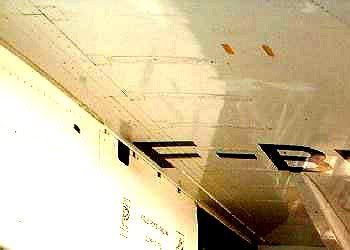
and as you see, they show up quite clearly on Fox Bravo as well.
Judging by the page dates in the SRM, BA started it all, and Air France followed, with all the aircraft being modified by 1981. But that's just my guess.
CJ
and as you see, they show up quite clearly on Fox Bravo as well.
Judging by the page dates in the SRM, BA started it all, and Air France followed, with all the aircraft being modified by 1981. But that's just my guess.
CJ
Join Date: Jan 2005
Location: France
Posts: 2,315
Likes: 0
Received 0 Likes
on
0 Posts
You're looking at a generic picture of the junction between the upper and lower skins of the innner and outer wings at the level of rib 12, which is the rib just outboard of the engines.
The 'sample' you're looking at in that diagram has been "cut away" between two spars. The strengtheners are on the spars themselves, so they don't show up here.
CJ
Join Date: Dec 2010
Location: Europe
Age: 88
Posts: 290
Likes: 0
Received 0 Likes
on
0 Posts
[xxxxquote=Mike Bracknell] Trust me, i'm definitely just here for the ride (so to speak) and quickly defer to you and the others who definitely know! Mike Bracknell[xxxx/quote]
Hell Mike, I meant I should leave it for others who definitely know, not you!
[xxxxquote]A little p.s. from me - having looked at Clive's diagram on this page showing the bathtubs, aren't the strengtheners the oval cups outboard of the main fixings on the page? with one pointed to by the words "Bottom machined skin panel"?
This looks like it's another layer of shear in order to fulfil the brief of working around the reported skin problems in that area. Just strange it had to break the surface like that? [xxxx/quote]
I don't think so Mike, there are far too many of them. It looks more like 'pocketing' of the machined skin to reduce weight; and incidentally that SA overdid it, since there were clearly cracks developing along the spanwise joints between the various wing sections.
Incidentally, doesn't that picture show ever so clearly why designing and fitting that postGonesse Kevlar liner to the lower skins was such a difficult job!
[xxxxquote=ChristiaanJ]If so, they are indeed shown in the structural repair manual and listed as 'doublers'. There are ten of those, from spar 62 to spar 71.
Reading "between the lines", the modification dates from about 1978, and was applied by successive service bulletins to both the BA and AF aircraft. [xxxx/quote]
Yes, I agree, they look like skin doublers put on as a repair job, and that makes (to me) a lot more sense than additions to increase outer wing stiffness. What has confused me from the beginning was that I equated "outer wing stiffness" with "outer wing torsional stiffness" because I could see why somebody might want to increase that but I couldn't, and can't, see why anyone would want to increase outer wing bending stiffness - if you get a little more dihedral who cares? But additional material to increase or recover fatigue life is another matter altogether.
Why external? Just look at that drawing - where could you add additional bending material easily?
[xxxxquote=Landroger]Digital control is a hell of a lot easier than Analogue - in my humble opinion.[xxxx/quote]
Depends when you were born Roger. Now if you came into this world before WW2 ......
[xxxxquote=Mr Vortex]I'm was wondering that, according to the manual and some document said that the vortex lift start to form on wing tip first. Why's that happened? Why not the root of the wing first?
Is it cause by the local wing tip vortex push the air causing more upwash
and hence more effective AoA causing it to reach the stall AoA first is that right?
Also, does the wing vortex on the Concorde has an influence or the effect on
the rudder? [xxxx/quote]
Ah! this gets a little complicated. Every lifting wing generates a pair of vortices at the tip, but these are not the vortices most people associate with Concorde. The massive vortices you see when the air is moist and the water vapour condenses out because of the drop in air pressure inside the vortex start, as you suggest at the wing root from that highly swept leading edge. The wingtip vortices are still there, even when the main vortices are doing their stuff, so Concorde actually has two sets of vortices acting on the upper surface, although this is not obvious to the casual observer.
Simply, the wing vortex has no effect on the rudder.
But whilst I am writing about vortices, can I digress to talk about the 'moustaches' aka GT6. Somebody, I forget who, asked about their use for controlling longitudinal stability and somebody else replied, quite correctly, that they were a contribution to lateral stability. What was happening without them was that high AoA (by which I mean in excess of about 10~12 degrees) the 'crossflow' on the front fuselage generated a pair of small vortices which, in sideslip, wandered across the base of the fin. This gave some sidewash that cancelled the 'incidence' coming from the sideslip itself so that the bottom of the fin was effectively operating at zero slip and therefore zero lift. Result - the weathercock stability dropped to virtually zero for small sideslip angles. The small vortex generators (Generator Turbillon or GT) had the effect of fixing the location of the origin of the forebody vortices so that they didn't wander - in fact they tended to become entrained into the main wing vortices - problem solved.
Now if I can sort it out I will try to upload some pretty pictures showing those two sets of wing vortices.
CliveL
Join Date: Dec 2010
Location: Europe
Age: 88
Posts: 290
Likes: 0
Received 0 Likes
on
0 Posts
 ">
">Dammit! I thought I had read that [xxxxquote] gave me one of those pretty text boxes ah well, back to the drawing board.....
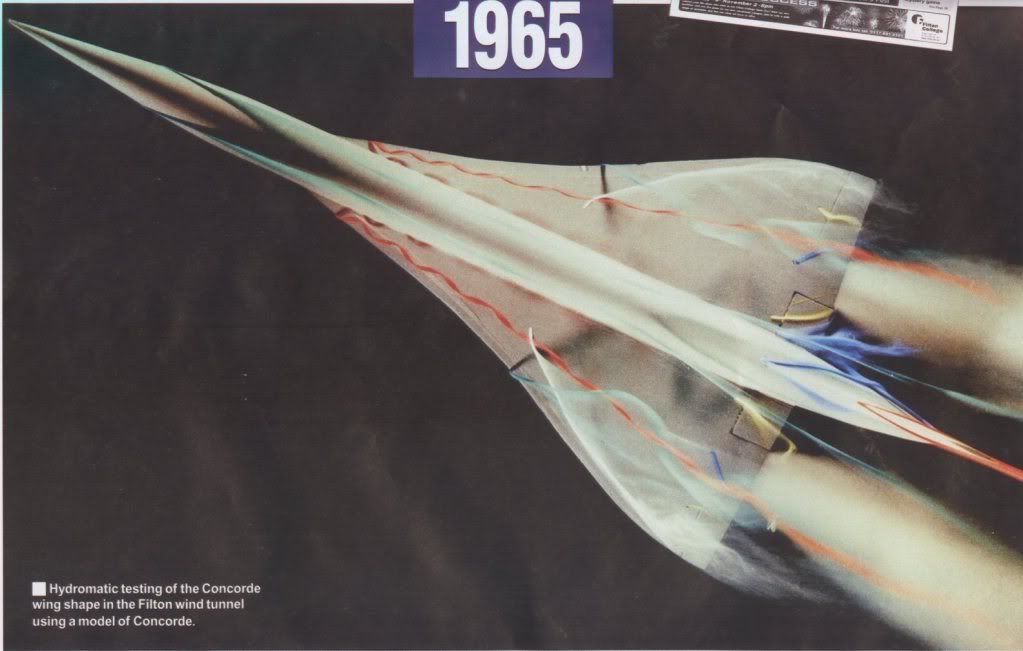
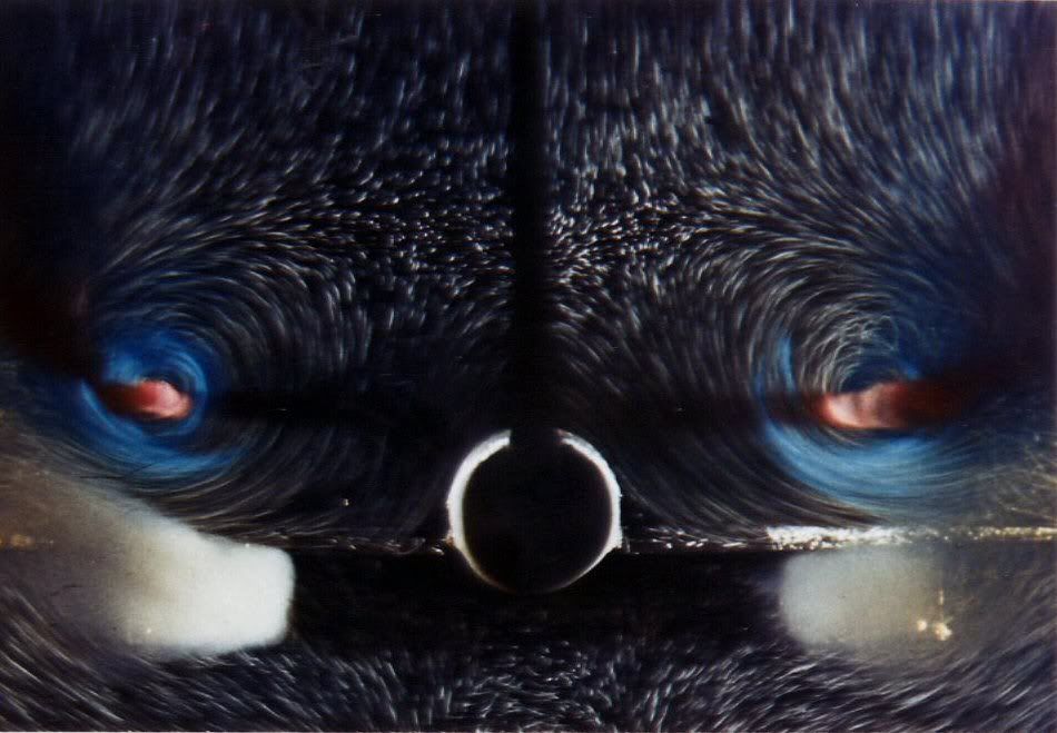
Unfortunately the only flow visualisation pictures I have are taken at AoAs where the tip vortex has been swallowed by the main vortex, but I thought I would paste them anyway as most people would never have seen them. In this one you can see the forebody vortices quite clearly (the bluegreen streaks) but since it is a zero sideslip case they don't go anywhere near the fin.
On closer inspection, maybe you can just see the wingtip vortices as separate bits of curly white smoke very close to each wingtip.
I'm not going to risk losing all that typing trying to attach a second picture, so I will send that separately
CliveL
Join Date: Nov 2010
Location: Beijing
Age: 30
Posts: 43
Likes: 0
Received 0 Likes
on
0 Posts
What an amazing pictures!!. Thanks CliveL
So does the nose stake of the aircraft that sit below the Capt/FO sliding window
is what you're refer to the GT6 things right?
And if possible, I would like to know why the vortex start to form on the wing tip
[The outer wing part] first and the moving toward the wing root [inner wing
part] as the AoA increase.
Thanks again
Best regards
So does the nose stake of the aircraft that sit below the Capt/FO sliding window
is what you're refer to the GT6 things right?
And if possible,
I would like to know why the vortex start to form on the wing tip[The outer wing part] first and the moving toward the wing root [inner wing
part] as the AoA increase.
Thanks again
Best regards