


Concorde question

Join Date: Jan 2008
Location: FL 600. West of Mongolia
Posts: 463
Likes: 0
Received 0 Likes
on
0 Posts
CliveL
Tee hee, can't get away with anything here anymore Clive  Yes, of course (as ever
  ) you are correct; it was technically a hybrid system: The servo loops, in terms of ramp and spill door demand signals and resolver position feedback signals etc. DID use conventional analogue drive and servo amplifiers within the AICU, it was the massive arithmetic computation UP-STREAM of these that was digital. I always used to like to refer to the AICS as 'an analog front end with a digital brain'. But that's just me
  .
.
But as you say Clive, none of the control law sophistication (including the synthesising the intake face total pressure and local Mach numbers from mainline aircraft raw air data) would have been possible using analog computation.
Best regards
Dude
I've noticed that several postings refer to the production AICU as a 'digital' control system. Strictly speaking it wasn't; it was a hybrid digital/analogue system where the inner dynamic control loops (the closed loop part) were analogue systems operating to maintain limits defined by the digital arithmetic processors. This allowed us to have quite sophisticated control 'laws' which would have been next to impossible with a pure analogue system.
Yes, of course (as ever ) you are correct; it was technically a hybrid system: The servo loops, in terms of ramp and spill door demand signals and resolver position feedback signals etc. DID use conventional analogue drive and servo amplifiers within the AICU, it was the massive arithmetic computation UP-STREAM of these that was digital. I always used to like to refer to the AICS as 'an analog front end with a digital brain'. But that's just me . But as you say Clive, none of the control law sophistication (including the synthesising the intake face total pressure and local Mach numbers from mainline aircraft raw air data) would have been possible using analog computation.
Best regards
Dude

Join Date: Jan 2008
Location: FL 600. West of Mongolia
Posts: 463
Likes: 0
Received 0 Likes
on
0 Posts
Mr Vortex
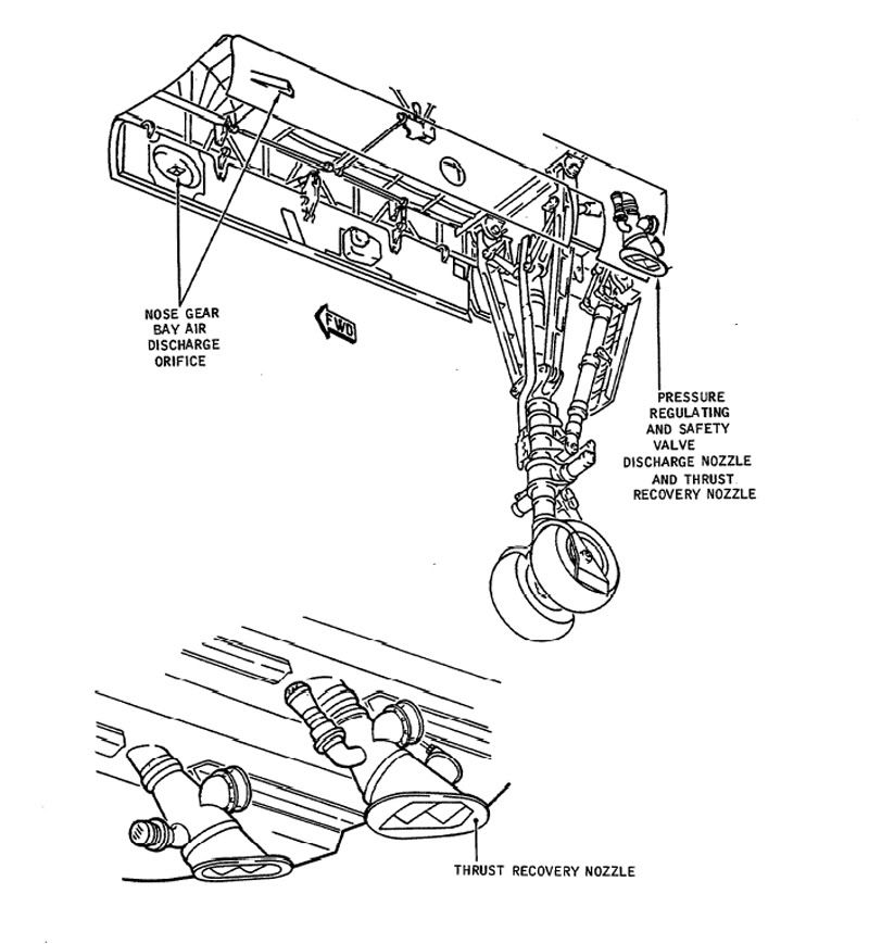
The Thrust recuperator (or thrust recovery nozzle) was fitted to the outlet of #1 (that is, left hand) forward discharge valve (outflow valve in Boeing speak) only. It was a variable 'louvre' type nozzle that would progressively close between 3 and 7.5 PSI diff'. The idea was to direct pressurisation outflow air directly backwards along (theoretically) the aircraft centre line (That at least was the theory). I read somewhere that at max diff' (10.7 PSIG) it would recuperate some 600 lb of thrust. HOWEVER, this system was fitted to the #1 system only (1 & 2 were used on alternate flights) and there was no performance penalty when the thing was not working. Here are a couple of diagrams.
Best Regards
Dude
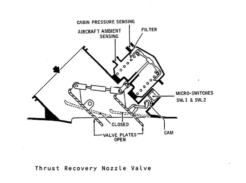
, What does the function of the Thrust recuperator and how does it work?
Best Regards
Dude
Last edited by M2dude; 23rd Dec 2010 at 09:42. Reason: I stil kant sprell
Join Date: Nov 2007
Location: Devon
Posts: 39
Likes: 0
Received 0 Likes
on
0 Posts
This just goes on getting better. Welcome Clive!
After all the high tech stuff I have a much more prosaic question. Looking out of my Devon window this morning I could see aircraft streaming up the channel, and by checking their positions on Flightradar 24 (sad, I know) I know that I can see craft at fl350+ nearly the whole way across the channel, so it occurs to me that I should have been able to see AF Concordes on their way into CDG, but never did (although I certainly heard them). Would Concorde have been visible from the ground at cruising height, and would it have left contrails?
After all the high tech stuff I have a much more prosaic question. Looking out of my Devon window this morning I could see aircraft streaming up the channel, and by checking their positions on Flightradar 24 (sad, I know) I know that I can see craft at fl350+ nearly the whole way across the channel, so it occurs to me that I should have been able to see AF Concordes on their way into CDG, but never did (although I certainly heard them). Would Concorde have been visible from the ground at cruising height, and would it have left contrails?
Join Date: Sep 2007
Location: UK
Age: 58
Posts: 128
Likes: 0
Received 0 Likes
on
0 Posts
Contrails
Concorde would produce contrails in the same conditions that a conventional aircraft would. I've seen pics of it contrailing in supercruise, and it's a big trail.
Outbound, for reasons of best efficiency, the subsonic cruise would be at FL260 or 280 so contrailing was unlikely, but I would expect the occasional contrail inbound (cruising in low- to mid-30's) so you were unlucky not to see one if you were looking at the right time.
It would have been no more or less visible on primary or secondary radar than other commercial types.
It would be hard to see with the naked eye, unless the sun was reflecting off it.
Join Date: Jan 2008
Location: FL 600. West of Mongolia
Posts: 463
Likes: 0
Received 0 Likes
on
0 Posts
Contrails

I took this one over the Atlantic, of G-BOAF, BA002 at Mach 2 FL 560 from G-BOAD FL 480 Mach 1.9 (test flight) in July 2003. (Mach 3.9 closing
 ).
).Best rgards
Dude
Join Date: Jan 2005
Location: France
Posts: 2,315
Likes: 0
Received 0 Likes
on
0 Posts
Shortly before the French end-of-service, a small group of French enthusiasts set out in a boat (fishing boat I think) to waypoint 'TESGO' in the Channel, to hear and capture the supersonic bang one more time (TESGO is already beyond the supersonic accel point).
They brought back a video which has become a classic, with both Concorde and a contrail overhead and a recording of the supersonic bang.
A quick search on the net for "TESGO" or "Operation TESGO" didn't produce anything, but I will make some enquiries.
CJ
Join Date: Apr 2009
Location: `
Posts: 309
Likes: 0
Received 0 Likes
on
0 Posts
Christian, is this the video you are refering to? YouTube - PHY NYC Concorde breaks sound barrier (double bang)
Post #879 http://www.pprune.org/tech-log/42398...ml#post6129540 - Just guessing now, but Bellerophon were you a Concorde Pilot by any chance.
I read your vivid description and realised that I must have been peeling onions at the same time. Thank you for that sensational work of art, drawing us a picture of that take off while at the same time making it sound like it was no harder than taking a breath, though I have no doubts this was an extremely complex and demanding proceedure that required a level of crew synergy unknown of at that time. Again, my THANKS for that precious insight into your world.
This in no way excludes all the other contributors to one of the two best threads on this Forum. All you guys made and were part of a very special piece of history and now like the famous "Few" will never be forgotten partly as a result of this thread.
I do hope Landlady posts back with pieces that didn't make it into her book.
Post #879 http://www.pprune.org/tech-log/42398...ml#post6129540 - Just guessing now, but Bellerophon were you a Concorde Pilot by any chance.
I read your vivid description and realised that I must have been peeling onions at the same time.
Thank you for that sensational work of art, drawing us a picture of that take off while at the same time making it sound like it was no harder than taking a breath, though I have no doubts this was an extremely complex and demanding proceedure that required a level of crew synergy unknown of at that time. Again, my THANKS for that precious insight into your world.This in no way excludes all the other contributors to one of the two best threads on this Forum. All you guys made and were part of a very special piece of history and now like the famous "Few" will never be forgotten partly as a result of this thread.
I do hope Landlady posts back with pieces that didn't make it into her book.
Last edited by Biggles78; 23rd Dec 2010 at 13:31.
Join Date: Jun 2008
Location: Outer space
Age: 53
Posts: 6
Likes: 0
Received 0 Likes
on
0 Posts
Originally Posted by Christiaan
A quick search on the net for "TESGO" or "Operation TESGO" didn't produce anything, but I will make some enquiries.
Join Date: Dec 2010
Location: Europe
Age: 88
Posts: 290
Likes: 0
Received 0 Likes
on
0 Posts
Originally Posted by ChristiaanJ
Clive, I think we need your help here. I was also told, both while I was at Fairford and during one of my two ground school courses at Filton in the early 80s, that the lateral stiffeners (underneath the wing just inboard of the Rib 12 area) were added to reduce outer wing flexure and in themselves gave us a performance penalty. Can you shed any light Clive?
I had never heard of any such stiffeners before I started reading this thread.
The wing inboard of Rib 12 was pretty stiff as was Rib 12 itself, so it didn't need stiffening there.
I don't see how tiny stiffeners like that, mounted INBOARD of Rib 12 could ever have have any significant stiffening effect on the wing OUTBOARD of Rib 12. if anyone wanted to stiffen the outer wing it would be much more efficient to do it with internal structure, so any external addition would have been some sort of panic measure and I think I would have heard of it.
The external shape of the excrescence looks to me much more like a streamlined fairing to get some sort of cable or pipe from A to B when for some reason it couldn't be passed through inside the wing. In this connection I see that the objects in question run fairly close if not along, area where one might have something going from tank 5a to 6 or 7 to 7a.
Yes there would be a small performance penalty for these fairings.
In summary I don't really know, but would need a lot of convincing that these things really were external stiffeners!
CliveL
Join Date: Jan 2005
Location: France
Posts: 2,315
Likes: 0
Received 0 Likes
on
0 Posts
CliveL,
Wasn't me, honest, guv. 'T was that other dude...
Any chance of a pic or a drawing, M2dude?
It seems almost impossible to me that it was 'something' between inner and outer wing, since it would have had to 'jump' over the bathtub covers.
IMO everything went through rib 12, not under or over it.
CJ
Wasn't me, honest, guv. 'T was that other dude...
Any chance of a pic or a drawing, M2dude?
It seems almost impossible to me that it was 'something' between inner and outer wing, since it would have had to 'jump' over the bathtub covers.
IMO everything went through rib 12, not under or over it.
CJ
Join Date: Dec 2010
Location: Europe
Age: 88
Posts: 290
Likes: 0
Received 0 Likes
on
0 Posts
Originally Posted by ChristianJ
Wasn't me, honest, guv. 'T was that other dude...
Any chance of a pic or a drawing, M2dude?
It seems almost impossible to me that it was 'something' between inner and outer wing, since it would have had to 'jump' over the bathtub covers.
IMO everything went through rib 12, not under or over it.
Any chance of a pic or a drawing, M2dude?
It seems almost impossible to me that it was 'something' between inner and outer wing, since it would have had to 'jump' over the bathtub covers.
IMO everything went through rib 12, not under or over it.
'Bathtub covers' rings a bell - we did have an issue designing fairingsfor these that looked remarkably like those in the photographs I've been looking at, but I'm damned if I can remember what the bathtubs were! (getting old again) Aren't those so called stiffeners actually the bathtub covers? Or have I completely misunderstood the question?
CliveL
Join Date: Dec 2010
Location: Europe
Age: 88
Posts: 290
Likes: 0
Received 0 Likes
on
0 Posts
Originally Posted by M2dude
HOWEVER, this system was fitted to the #1 system only (1 & 2 were used on alternate flights) and there was no performance penalty when the thing was not working.

Dude, Do you know how the #2 system was exhausted if it wasn't through another thrust recovery nozzle? We were never going to throw away 600 lbf thrust every other flight - not on Concorde where we sweated blood to get the parasitic drag down!
Any chance that there was a common discharge point even if the two packs were used alternately?
CliveL
Join Date: Sep 2007
Location: UK
Age: 58
Posts: 128
Likes: 0
Received 0 Likes
on
0 Posts
That's not my recollection - no.2 system used for inbound flights, and this used the stbd outflow (oops! discharge) valves.
No perf penalty, as 'Dude noted. I vaguely recall being told that the drag from the recuperator cancelled a lot of the recovered thrust. I've no idea how true it was.........
No perf penalty, as 'Dude noted. I vaguely recall being told that the drag from the recuperator cancelled a lot of the recovered thrust. I've no idea how true it was.........
Join Date: Dec 2010
Location: Europe
Age: 88
Posts: 290
Likes: 0
Received 0 Likes
on
0 Posts
no.2 system used for inbound flights, and this used the stbd outflow (oops! discharge) valves.
No perf penalty, as 'Dude noted. I vaguely recall being told that the drag from the recuperator cancelled a lot of the recovered thrust. I've no idea how true it was.........
No perf penalty, as 'Dude noted. I vaguely recall being told that the drag from the recuperator cancelled a lot of the recovered thrust. I've no idea how true it was.........
I know it sounds crazy, but that cabin air had to be dumped somewhere, and without those thrust recovery nozzles all the energy it contained would be lost, so that a net zero is actually a win!
CliveL
Join Date: Jan 2005
Location: France
Posts: 2,315
Likes: 0
Received 0 Likes
on
0 Posts
Originally Posted by CliveL
but I'm damned if I can remember what the bathtubs were!
OK all.
On the 'blunties' and most other aircraft (subsonic or supersonic) there is a fuselage, and there is a wing.
The wing is connected to the fuselage by only a few very big bolts, linking a few very big forgings.
Concorde is different, right? Right.
Fuselage and inner wing are the same structure, and there were no "big bolts" that allowed you to separate fuselage and inner wing once the aircraft was built.
The only separate "bits" were the outer wings, the parts just outside the engine nacelles.
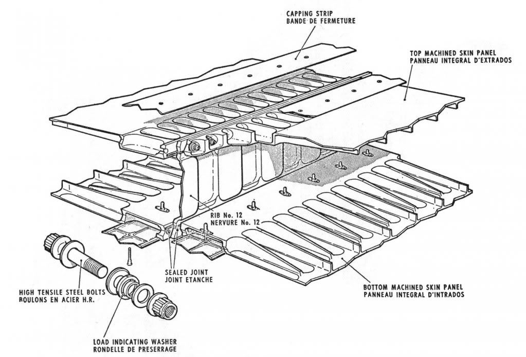
So 'rib 12' was the rib where the inner wing ended, and where the outer wing (built by Dassault, rather than Aerospatiale, actually) was attached.
Rib 12 actually was two halves, the one at the outboard side of the inner wing, and the one on the inboard side of the outer wing.
Both machined numerically from single 'blanks'...
And no, these two halves were NOT just bolted together with a few massive bolts. They were bolted together with hundreds of bolts in all. I did say Concorde was different, no?
Words now fail me, and I'll have to find or scribble some drawings ASAP.
In brief, so far.. each half of rib 12 had MANY machined "bath tub shaped" slots allowing to insert a bolt between the two halves, and bolt the outer wings to the inner wings.
And simplistically, the 'bath tub covers' were just small sheet panels held in place with fasteners fitted inside the 'bath tub' slots.
I should know.... I still have the scars of helping, one day, to refit a batch of them on Delta Golf at Brooklands
CJ
Join Date: May 2002
Location: UK
Posts: 140
Likes: 0
Received 0 Likes
on
0 Posts
A couple of points on some of the latest entries
Discharge valves
We definately used alternating systems outbound and inbound and only No 1 system had thrust recuperators. I think the original idea was that No 1 system would be used always with No 2 sytem being a back up. However from the start BA operated as I said alternating per sector so as to be sure that both system were working. The same logic went for the engine starting ignitors which were used Lh or Rh per sector. This logic caused more problems with starting than any other although a way was found to over come this problem
under wing
Not sure if I am on the same thread as others but there were definately strengthening straps / doublers fitted on the underside of the wing outboard of the engines, which were on a wing root/wing tip alignment. This surprised everybody as they seemed to go against all the need for limiting drag that had been impressed on us during the lectures.
These strengthening straps were fitted a few years after the start of service due to small cracks appearing in the outer wing, and only seen on BA aircraft. This was put down to the fact that in the early years BA Concordes flew heavy and subsonic for extended periods across Europe, on their route to Bahrain, whereas Air France aircraft always accelerated shortly after take off
Also either side of the engines there were two tubes on the underwing which went fore /aft. These tubes were the drain outlet for their respective engine dry bay and directed any fluid to the trailing edge of the wing.
Mind you all this is some 30 years ago so the old grey matter could be playing me tricks
Join Date: Dec 2010
Location: Europe
Age: 88
Posts: 290
Likes: 0
Received 0 Likes
on
0 Posts
A picture is worth a thousand words they say, but the bathtub joints can't be the fairings showing just outboard of the nacelles as they (the bathtub joints) are flush
CliveL
CliveL
Join Date: Dec 2010
Location: Europe
Age: 88
Posts: 290
Likes: 0
Received 0 Likes
on
0 Posts
Originally Posted by Brit312
Not sure if I am on the same thread as others but there were definately strengthening straps / doublers fitted on the underside of the wing outboard of the engines, which were on a wing root/wing tip alignment. This surprised everybody as they seemed to go against all the need for limiting drag that had been impressed on us during the lectures.
These strengthening straps were fitted a few years after the start of service due to small cracks appearing in the outer wing, and only seen on BA aircraft. This was put down to the fact that in the early years BA Concordes flew heavy and subsonic for extended periods across Europe, on their route to Bahrain, whereas Air France aircraft always accelerated shortly after take off
Also either side of the engines there were two tubes on the underwing which went fore /aft. These tubes were the drain outlet for their respective engine dry bay and directed any fluid to the trailing edge of the wing.
If there were spanwise straps fitted to BA aircraft after a few years in service that was after my time. They would be a sort of 'crack stopper' and despite the drag would have to go spanwise to carry the loads and would have to be external at that stage in the aircraft life. They would give some additional bending stiffness, but not very much I think. they are probably invisible in any photographs I have - the 'fairings' I have been chuntering on about are the dry bay drains you have just described.
I must admit I am surprised by your remarks on the thrust recovery nozzles though.
CliveL