


Big Crash at Reno


Join Date: Aug 2011
Location: Grassy Valley
Posts: 2,074
Likes: 0
Received 0 Likes
on
0 Posts
Re: Fuel supply? If dependent on atmospheric pressure in any way, or even with positive pressure electronic pumps, isn't the fuel mass going to be quite lethargic at 12 G? One suspects cavitation, or vapor lock.
RH elevator. With the trim tab set for ND on the LEFT side, the LHE has some of its up force relieved at the Bellcrank. The RHE has no such advantage, and the stress is greater at the RHE join. This reverses with Pitch, and there is a chronic war twixt the right and left sides of the torque tube joins. Each reversal of elevator position causes two of these torsional reversals rather than one. So fatique is doubled, and the throughbolts are not designed for this, imo. (Notwithstanding the design consideration does not include these torsional challenges, originally).
What results is an inadvertent "warping" effect, through the hinge line of the Horizontal tail. The design is counter to such a consideration, imo. Again, if the design were to be carried through, and there is no reason to abandon the idea, the Torque tube would be a unit, not halves.
I select the RHE for failure because of this stress bias against it. I take note of the quote above. Mark Twain was editor of the "Territorial Enterprise" in Virginia City, just down the road from STEAD AFB, so that makes him a local, and had he lived, he likely would be flying some "contraption" at RENO each September.
He was an accomplished PILOT. SteamBoat wise.
For the Merlin, then. Fuel Injection? For the Mustang, CFRP tail feathers and Fuselage? Tame the skin, lose the drag. And a Stout Torque Tube for the els.
Klink: Newton's Third? In failure,the stress is differential, not opposite, imho. The Third applies to the controls' NET effect on the airframe?
Last edited by Lyman; 14th Oct 2011 at 15:30.
Join Date: Jul 2009
Location: Not far from a big Lake
Age: 82
Posts: 1,454
Likes: 0
Received 0 Likes
on
0 Posts
It has also been mentioned that the doors also came off and this was an indication of structural damage to the tail due to flutter/twist/or the tab failure.
C-C et al, just to go back to my earlier reference to the article by Space-Electronics; it refers to mass balancing of control surfaces,not specifically `tabs`,more as a unit and `Moment of Inertia`,but also considers Product of Inertia` being the spanwise distribution of mass balances on control surfaces.Also that this factor seems to be largely `ignored`.
In the Mustang case, the ailerons appear to be balanced along their span( indeed in `Wrench`s link to `Aircorps` there was an early modification to the Mustangs` ailerons to replace the left aileron mass balance,made of steel` with one of a non-magnetic material as it interfered with the compass detector in the wing.)
However, the elevators and rudder,have solid balances towards their tips in each case,and do not appear to be balanced along their span,,ie, not taking `product of inertia` into account.
In the event of `flutter` starting,for whatever reason I would suspect that there will be a very rapid and
strong torsional twisting between the elevators and along the elevators due to the mass balance concentration at the tips,and as visible in the `V` tail glider elevons.
I realise that the m-b weights may also be aerodynamic balances,and there is not a lot of room in front of the elevator to the rear spar unlike the ailerons which appear to be `shrouded` on top and bottom.Perhaps your contacts may know more about that.....Did NA miss a trick here when it was designed
ed; does anyone know of othe incidents of `flutter` on other types,either racing or airtesting,as it seems that Mustangs have had a few tab failures including rudders..?
NB.I have nothing against Mustangs,just want to explore all avenues if possible...
Last edited by sycamore; 15th Oct 2011 at 21:52.
Join Date: Jul 2009
Location: Not far from a big Lake
Age: 82
Posts: 1,454
Likes: 0
Received 0 Likes
on
0 Posts
Little Clues
A few posts earlier I asked the question whether or not the Ghost had an elevator bobweight installed. I think I have found the answer, but look for yourself.
First Clue: From http://en.wikipedia.org/wiki/The_Gal...host_(aircraft)
600 lbs removed from a P-51 is a lot of weight, I think I have found where 20 lbs of that weight came from.
Second Clue is this third hand post from post 291 in this very thread: http://www.pprune.org/6736071-post291.html
Third clue is from TECHNICAL ORDER NO. 01-60J-29 found here: http://www.aircorpsaviation.com/Webs...ges/60J-29.pdf
Fourth clue from the same source:

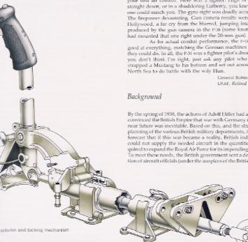
The elevator control bellcrank assembly is mounted just aft of the cockpit on the flap torque tube. The twin up and twin down elevator cables run from the elevator control bellcrank assembly and attach to the two arms on the elevator bellcrank that we have seen previously. This was done for combat survivability reasons but it had certain other advantages as well.
Fifth clue is this picture from the tech order:

Here we see what the elevator control bellcrank looks like and what the bobweight added to the bellcrank looks like.
Sixth and final clue is this picture segment brightened a bit to show the shadowed area taken from the build up of the Ghost. Do you see the elevator control bellcrank? It is mounted on the slightly copper colored shaft. Do you see a bobweight? Do you think you should be able to see it if it is there?

Removal of the elevator bobweight could cause handling problems and could leave the elevators subject to flutter for the reasons just stated by sycamore since the bobweight acts to damp out oscillations in the inboard sections of the elevator, particularly if both pairs of cables are in place. I am fairly sure that the bobweight is not in the picture, but I am not 100 % positive.
Was it a victim of the long ago weight saving campaign? Could that be what happened to the starboard trim tab actuator as well?
First Clue: From http://en.wikipedia.org/wiki/The_Gal...host_(aircraft)
Sanders renamed the aircraft Jeannie, after his wife. The aircraft was rebuilt with an eye to weight reduction. In the end, 600 lbs of was removed from the airframe.[14] Roy �Mac� McLain flew the aircraft in 1979 at the Reno Air Races. Shortly before the 1980 air races, the aircraft was damaged in a crash at the Van Nuys Airport. In a frantic effort, the aircraft was rebuilt and again flown by McLain, won the Gold Race at Reno just days later. At the 1981 Reno Air Races, Skip Holm piloted the aircraft to victory in the Unlimited Class Gold Race.
Second Clue is this third hand post from post 291 in this very thread: http://www.pprune.org/6736071-post291.html
During qualifying Matt watched Galloping Ghost from inside the cockpit of Furias and could not believe how much trouble Leeward was having in keeping the Ghost in a stable pattern around the course.
NORTH AMERICAN-INSTALLATION OF ELEVATOR INERTIA WEIGHT P-51B, P-51C, AND P-51D
1. PURPOSE.
To prevent reversal of the elevator control stick
forces during maneuvers, an elevator inertia weight
will be installed in accordance with the instructions
contained in paragraph 2. in all of the following airplanes.
1. PURPOSE.
To prevent reversal of the elevator control stick
forces during maneuvers, an elevator inertia weight
will be installed in accordance with the instructions
contained in paragraph 2. in all of the following airplanes.
The elevator control bellcrank assembly is mounted just aft of the cockpit on the flap torque tube. The twin up and twin down elevator cables run from the elevator control bellcrank assembly and attach to the two arms on the elevator bellcrank that we have seen previously. This was done for combat survivability reasons but it had certain other advantages as well.
Fifth clue is this picture from the tech order:
Here we see what the elevator control bellcrank looks like and what the bobweight added to the bellcrank looks like.
Sixth and final clue is this picture segment brightened a bit to show the shadowed area taken from the build up of the Ghost. Do you see the elevator control bellcrank? It is mounted on the slightly copper colored shaft. Do you see a bobweight? Do you think you should be able to see it if it is there?
Removal of the elevator bobweight could cause handling problems and could leave the elevators subject to flutter for the reasons just stated by sycamore since the bobweight acts to damp out oscillations in the inboard sections of the elevator, particularly if both pairs of cables are in place. I am fairly sure that the bobweight is not in the picture, but I am not 100 % positive.
Was it a victim of the long ago weight saving campaign? Could that be what happened to the starboard trim tab actuator as well?
Join Date: Sep 2011
Location: San Antonio Texas
Posts: 6
Likes: 0
Received 0 Likes
on
0 Posts
Bob weight
Modern aircraft have bob weights installed mainly to solve phugoid problems. The bob weight has no effect on mass balance. Given the amounts of turbulence likely to be encountered during the race and the speeds, the elevators would have been better balanced with the weight distributed along the leading edge and not with most of it located in the horn.
Join Date: Aug 2011
Location: Grassy Valley
Posts: 2,074
Likes: 0
Received 0 Likes
on
0 Posts
Machinbird. With respect, the Flap TT blocks the area where one expects to see the Bobweight. Flutter can happen with highly tensioned actuators, as these are not. Even with hydraulics. The cables would not be sufficiently robust to blank flutter, imho.I notice the default arm of the weight tensions Nose UP, curious the design thought behind that.
What a treat, your drawings, and comment, thanks.
What a treat, your drawings, and comment, thanks.
Join Date: Jul 2009
Location: Not far from a big Lake
Age: 82
Posts: 1,454
Likes: 0
Received 0 Likes
on
0 Posts
Stressmerchant
It appears that the P-51 had a bit of a tendency to experience stick force lightening at higher g levels without the bobweight. The Technical Order specifically states,.
So the bobweight was there for stability reasons and not for phugoid reasons.
Any tendency to stabilize the elevator was an added bonus.
Ideally you want the counterbalance mass evenly distributed and firmly attached to the control surface, but in practice this can be difficult. As I recall, my F-4 had rudder mass balances in a shielded horn near the tip and out of sight in the fuselage.
If you have time, read into this link about Strega and what happened when they switched to a "tube" engine. Tiger Paws
Was the bobweight there for stability reasons, or was it the flutter balance weight?
PURPOSE.
To prevent reversal of the elevator control stick forces during maneuvers
To prevent reversal of the elevator control stick forces during maneuvers
Any tendency to stabilize the elevator was an added bonus.
Ideally you want the counterbalance mass evenly distributed and firmly attached to the control surface, but in practice this can be difficult. As I recall, my F-4 had rudder mass balances in a shielded horn near the tip and out of sight in the fuselage.
If you have time, read into this link about Strega and what happened when they switched to a "tube" engine. Tiger Paws
Join Date: Sep 2011
Location: Nevada
Age: 57
Posts: 18
Likes: 0
Received 0 Likes
on
0 Posts
Lyman, I guess I'm looking at the drawing wrong, but the weight would want to rotate the bellcrank ccw (per drawing) thus pulling on the control rod on the stick actually moving it forward.....(nose down). Countering a severe positive g climb......or am I backwards? But could understand the need to remove some of it in racing conditions.
If you guys go to `keypublishing.com` and look at `historic aviation` ,there is a thread about the restoration of a TF-51. There are a lot of photos,some relevant but near the end of p.2 there is a photo of the lower controls with the bobweight.
Join Date: Aug 2011
Location: Grassy Valley
Posts: 2,074
Likes: 0
Received 0 Likes
on
0 Posts
Hi sycamore. I am basing my thoughts on a pushrod that is mounted above the pivot bearing of the stick, not below it. Hence forward stick pulls the pushrod forward, and the crank articulates CW. It is a guess, but it puts the minor bearing "inside" the Stick bearing, protecting it, and saving additional Stick length.
again, a guess.
again, a guess.
The `exploded view ` of the mod. is looking aft,and also the photo at #54 on that thread.The bobweight is forward of the stick pivot,so under `g` loading it pulls down increasing the `stick-force per G increment,and the same for negative G.In the TF51 case it may be further back as it`s got full dual controls.
I would think that for the weight reduction for racing there would be a lot of extra hardware,ex-mil, that could be removed without touching the controls,or maybe just reducing the bobweight somewhat..
I would think that for the weight reduction for racing there would be a lot of extra hardware,ex-mil, that could be removed without touching the controls,or maybe just reducing the bobweight somewhat..
Join Date: Dec 2007
Location: Cape Town
Age: 70
Posts: 440
Likes: 0
Received 0 Likes
on
0 Posts
Three small hinges and 3 small screws held the trim tab in place.( on the original)
That should give an idea of the expected trim tab forces.
I am not surprised that the tab came off at the speeds and forces it experienced.

That should give an idea of the expected trim tab forces.
I am not surprised that the tab came off at the speeds and forces it experienced.
Join Date: Jul 2009
Location: Not far from a big Lake
Age: 82
Posts: 1,454
Likes: 0
Received 0 Likes
on
0 Posts
Sycamore, thanks for the link to the TF-51 build.
Last edited by Machinbird; 17th Oct 2011 at 18:59. Reason: Remove referece to a possible viscous damper-more likely it is the rear stick input.
Join Date: Sep 2011
Location: Nevada
Age: 57
Posts: 18
Likes: 0
Received 0 Likes
on
0 Posts
web find, that claims this is P-51
Also, does anybody else hear a "POP" at the begining of the "medium speed" portion of the climb video, in addition to the "CLICK" heard later in the climb? Just wondering......
Oh, and thanks for the heads up on the tf-51 build up, thats pretty amazing stuff.
Also, does anybody else hear a "POP" at the begining of the "medium speed" portion of the climb video, in addition to the "CLICK" heard later in the climb? Just wondering......
Oh, and thanks for the heads up on the tf-51 build up, thats pretty amazing stuff.
Last edited by xmh53wrench; 18th Oct 2011 at 02:12.
So does the bobweight double as the balance weight? Or is there a specific balance weight?
Perhaps out the fitting near the tip?
Does anyone know what the original (fabric covered) and later elevator balance limits were?
Perhaps out the fitting near the tip?
Does anyone know what the original (fabric covered) and later elevator balance limits were?


Join Date: Jun 2009
Location: ATL
Age: 67
Posts: 131
Likes: 0
Received 0 Likes
on
0 Posts
Excuse the absence. It's fall around here and the GF scheduled a cabin vacation. Surprise.
Have found some change orders from back in the day, and the bob weight is included;
Tech INFO - Aircorps Aviation
They strengthened the horizontal and vertical, but there are no tell-tale signs of any elevator problems, other than the plastic trim tabs and maybe the outer hinge. The mechanics would ensure the mods are complete on the current airplanes.
Also did a stress analysis of the torque tube and if I did it right, for a 9 g turn at Reno, it's only 5 kpsi. Yield for 2024-T3 is around 45 kpsi, so fatigue or outright failure of the tube is low probability. That leaves the attachment analysis. Contacted a restorer in Texas and will try to talk him into drilling off the D spar of a damaged elevator to get the attachment details. Or, if anybody has the blueprints, or details, that would be better.
Join Date: Jul 2009
Location: Not far from a big Lake
Age: 82
Posts: 1,454
Likes: 0
Received 0 Likes
on
0 Posts
I have found a picture of the ghost made during the engine run ups after joining the wing and fuselage. At that time, the bobweight is definitely not there.
The green circle marks where it would be visible. All that is there is the elevator control bellcrank upper arm.
A bobweight would mitigate the nose up input that occurred at the beginning of the accident.

The green circle marks where it would be visible. All that is there is the elevator control bellcrank upper arm.
A bobweight would mitigate the nose up input that occurred at the beginning of the accident.