


My Tornado GR1 cockpit project so far

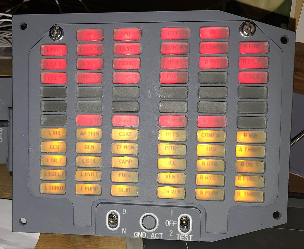
Test 1 tested the bulbs and audio, test 2 from memory simulated certain conditions to set some of the warnings off; hence you couldn�t use Test 2 in flight because ambient temps might hard-latch a warning on. That�s my hazy memory from a few years back anyway.

Thank you. I'm making some fake instruments for a flight sim and wondered what logic to apply to the two test modes. I can't post any pictures yet as this is my third post and I need ten to be able to post pictures but when I have the CWP more functional I'll put some up.

Join Date: Jun 2021
Location: Blackpool
Posts: 2
Likes: 0
Received 0 Likes
on
0 Posts
DZUS success
Quite s lot of success in the last month or so. Found a German eBayer supplying DZUS rail at a decent price. Far far cheaper than some aircraft grade stuff I bought years ago. Now have all side panels from front and rear seats neay laid out. Was also able to cheaply buy a HUD body Nd control panel separately. The HUD body doesn't have the frame for the holographic glass ... But that's not a prob as I don't need the glass. I'll 3D print up the frame. Will post some snaps tomorrow.
Join Date: Feb 2006
Location: Hanging off the end of a thread
Posts: 33,076
Received 2,942 Likes
on
1,253 Posts
There is some head up display glasses on eBay, see
https://www.ebay.co.uk/itm/324379009...4AAOSwB8BftRXU
https://www.ebay.co.uk/itm/324379009...4AAOSwB8BftRXU
Quite s lot of success in the last month or so. Found a German eBayer supplying DZUS rail at a decent price. Far far cheaper than some aircraft grade stuff I bought years ago. Now have all side panels from front and rear seats neay laid out. Was also able to cheaply buy a HUD body Nd control panel separately. The HUD body doesn't have the frame for the holographic glass ... But that's not a prob as I don't need the glass. I'll 3D print up the frame. Will post some snaps tomorrow.
Is DZUS rail a standard size? Would you know the distance between centres that the Tornado uses if not as I might be able to use that to determine the size of some of the panels in the sides.
I'm making a cockpit for the X-Plane 11 simulator, I've finished the Combined Surfaces Indicator (except for the lighting) and have nearly finished the engine start panel and have the CWP, Fuel gauge and V/UHF radio in various stages of manufacture.
When I have ten posts I can put some pictures up.
Join Date: Feb 2006
Location: Hanging off the end of a thread
Posts: 33,076
Received 2,942 Likes
on
1,253 Posts
It might be a modified aircraft with a revised limit at a guess.
I’m not sure I ever understood it, let alone remember it but all aircraft Had these figures on the glass, and it is to do with tolerances on engine test figures. They enabled the pilot to check that the engine was functioning within limits prior to take off, and the limits were different on each engine according to calibrated figures.
Placarded figures from the last Engine Ground Run (EGR) that shows the crews whether the engine is performing as it should (within the placarded limits). There was also a time when we used to have to run and write down the engine figures before take off to allow close monitoring of the engine performance in the mid-90s when engines were alarmingly going catastrophically �bang� from time to time! 
Join Date: Feb 2006
Location: Hanging off the end of a thread
Posts: 33,076
Received 2,942 Likes
on
1,253 Posts
There was also a time when we used to have to run and write down the engine figures before take off to allow close monitoring of the engine performance in the mid-90s when engines were alarmingly going catastrophically ‘bang’ from time to time!
Thread Starter
It has been a while since I have posted any updates on my project, truth is it's getting really hard toi find the last few things I need to complete it, but I have made some small changes, only the keen eye will notice.
I have now got all the correct buttons for the HUMS (head up mode selector) box which has the autopilot controls. I was missing the THROT button which was the autothrottle control, there was just a NEXT TGT button in it's place, so that's now been fixed. also the TF (terrain following) has been swapped, the one I had was for Tornado GR4 and just looked like a blank button, only if I shine a light on it you could see it said TF, i think that was for NVG, used in GR$ version, as my cockpit is supposed top represent a GR1 I managed to swap it for a GR1 version which the TF caption is visible.
The most obvious addition is the HUD camera periscope which fits in the cut out in the HUD glass, that was a bit of a tricky thing to fit, I had to remove the glass from the HUD.
There are a couple of non genuine parts but they are quite in obscure so not worried about that, one is the mount for the MASS, I was unaware it had a mount until I saw someone had made some reproductions. and finally my HUD was missing the round bit of glass which has a green colour so i just got a disk of green acrylic cut to size and it slotted into place it looks OK, better than having nothing.
There's not really much more I can do with the main instrument panel, There are 2 buttons I would like to replace with the correct ones but I have never seen any. I don't even know what those buttons were for so I cannot search for them. I also need a pedal adjust knob it looks like I may have to go down the replica route with that but I can live with that.
Really now my main task is to built a structure to support it all so I can put the rudder pedal assembly in place and finally get rid of the cardboard box its all supported on, it will look 100 times better then. And then I can work on the side consoles and getting the quarter panels in place.
Thanks for the trip down memory lane. I never knew the full panel but I was quite familiar with the RPMD and the CRPMD. As an assistant engineer fresh out of Uni I accepted the A models for the EASAMS test rig and ran the integrated system tests. That film transport mechanism was a mechanical delight!
Last edited by EXDAC; 22nd Nov 2022 at 12:42.

Join Date: Feb 2006
Location: Hanging off the end of a thread
Posts: 33,076
Received 2,942 Likes
on
1,253 Posts
Looking exceptional, btw don’t open the link below..it can seriously damage your wallet.
https://www.ebay.co.uk/itm/155263016...Bk9SR-7Bm9aTYQ
https://www.ebay.co.uk/itm/155263016...Bk9SR-7Bm9aTYQ
The following users liked this post:
Join Date: Feb 2006
Location: Hanging off the end of a thread
Posts: 33,076
Received 2,942 Likes
on
1,253 Posts
Looking good Stacker, sorry cannot answer your questions, see what you mean price wise
https://www.ebay.co.uk/itm/125787006...Bk9SR4z2os_pYQ
https://www.ebay.co.uk/itm/125787006...Bk9SR4z2os_pYQ
Last edited by NutLoose; 4th Apr 2023 at 16:11.
Join Date: Feb 2006
Location: Hanging off the end of a thread
Posts: 33,076
Received 2,942 Likes
on
1,253 Posts
https://www.ebay.co.uk/itm/185644301...Bk9SR5CO2s_pYQ
https://www.ebay.co.uk/itm/185635598...Bk9SR5CO2s_pYQ
This harrier one looks totally different
https://www.ebay.co.uk/itm/185727528...Bk9SR5CO2s_pYQ