


Alaska Airlines 737-900 MAX loses a door in-flight out of PDX

Join Date: Aug 2009
Location: GPS L INVALID
Posts: 580
Likes: 0
Received 0 Likes
on
0 Posts
Originally Posted by AMM
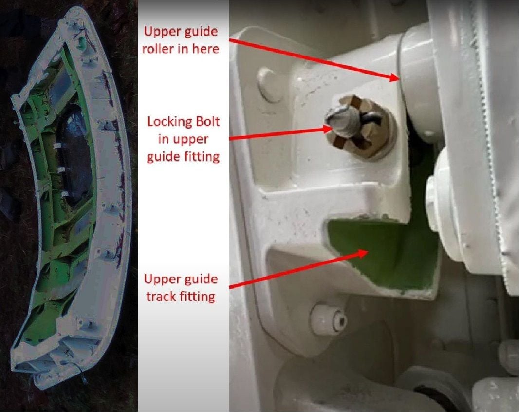
Control Cabin Door Decompression Panels
The door has blowout panels that will open if there is a rapid decompression in the flight compartment. A rapid decompression will cause a sudden change in pressure between the flight compartment and the passenger cabin compartment. For each decompression panel, one edge is attached to the flight compartment door assembly with retractable bolts, while the other edge is secured to the door assembly with a mechanical pressure release latch. The mechanical latches are set to release under a pre-determined pressure, which will cause the decompression panels to open into the flight compartment.
In the case of a rapid decompression in the cabin compartment, the door is able to withstand the pressure difference due to the small area of the flight compartment.

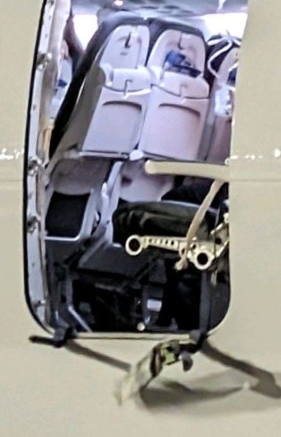
From the inside view, it can also clearly be seen that the bottom part of the aft hinge is intact and attached securely. The spring has been released as lateott pointed out in post 497, but I would argue that the locking pin is still in place, and the problem is that the bracket itself (which holds the locking pin) has come loose.

Join Date: Nov 2021
Location: Wisconsin
Posts: 2
Likes: 0
Received 0 Likes
on
0 Posts
I had considered a scenario in which improper installation of the upper locking bolts could cause fracture of the guides. I resisted posting until now.
Let's assume there is no spacer coaxial with the locking bolt. These locking bolts just need to be "snug" to perform intended function. What if the normal "book" torque was used on the locking bolts nuts when/if they were fitted? I suspect this would squeeze the guide channel subjecting it to loads it was not designed to withstand.
Let's assume there is no spacer coaxial with the locking bolt. These locking bolts just need to be "snug" to perform intended function. What if the normal "book" torque was used on the locking bolts nuts when/if they were fitted? I suspect this would squeeze the guide channel subjecting it to loads it was not designed to withstand.
Psychophysiological entity
the cracked guides were a consequence, rather than a cause,
-----------------------------
To me, the use of lock washers has always been an issue even with ordinary engineering. The ones that really bite are probably too destructive for aircraft. There seems to be no cutting edges on the bracket bolt washers.

Join Date: May 2011
Location: U.S.
Posts: 84
Likes: 0
Received 0 Likes
on
0 Posts
Originally Posted by Stribeck;
From the inside view, it can also clearly be seen that the bottom part of the aft hinge is intact and attached securely. The spring has been released as lateott pointed out in post 497, but I would argue that the locking pin is still in place, and the problem is that the bracket itself (which holds the locking pin) has come loose.
It very much looks as if the distance the door plug needs to lift to clear the stops is less than the distance needed to disengage the rollers from the guides. That wouldn't be a problem in the hangar, but in the air (assuming no bolts fitted) the door would depart as soon as the stops were cleared and while the rollers were still engaged in the guides.
No prizes for guessing what would almost certainly happen to the guides in that scenario,
No prizes for guessing what would almost certainly happen to the guides in that scenario,
What are the chances, while all this is going on, of replacing short/medium term the "plugs" with a proper, already certified door at this position, like the high density users who are carrying on unrestricted, and doing without a few seats in the interim.
Join Date: Mar 2007
Location: In my head
Posts: 694
Likes: 0
Received 0 Likes
on
0 Posts
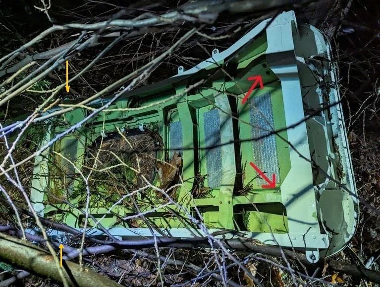
Also can we perhaps just make out apparent dissimilarities in shape between Left and Right Hand Side tracking guides in the "plug in the bushes" pic (my yellow arrows)?
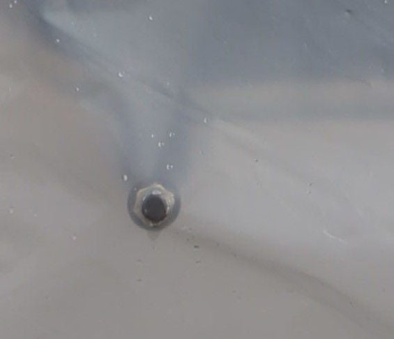
And what exactly are we looking at in Mudman's first three photos - are those bolts protruding out of the fuselage in his marked positions 1 & 2 under NTSB's plastic?? Can't be - nothing protudes below the outside of a closed plug, does it, or even below a part open one ... must be another trick of the light ...
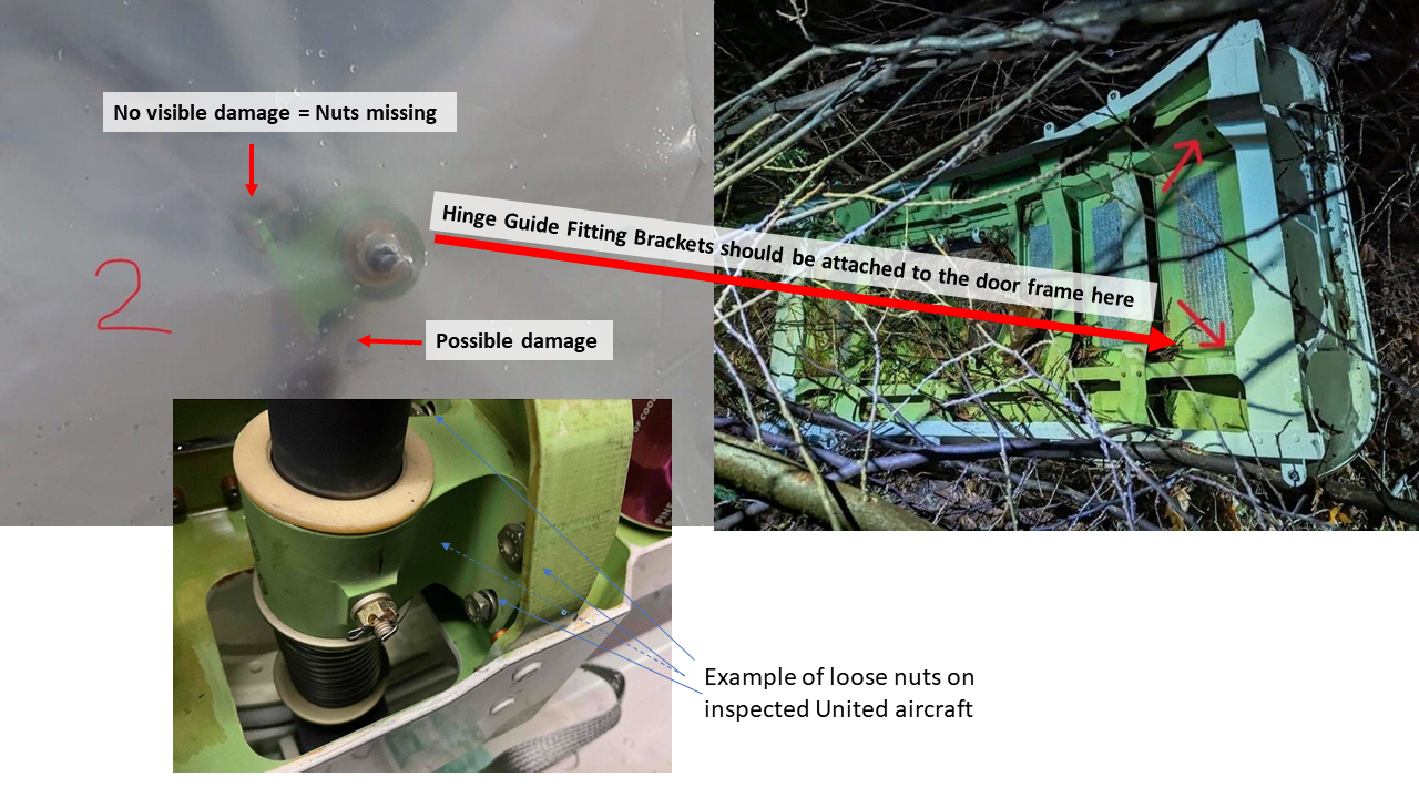
And finally, I am with Mudman on his astounding last pic of the hinge on an inspected United aircraft - what design feature stops the hinge collar securing bolts from coming loose?
S&T
Moderator
The metal casing really isn't very thick and the safety bolt hole takes away more of the substance to the guide. Getting thumped by the roller pin on the upstroke* might just start the casting cracking.
Though Boeing may prescribe a more specific procedure, in general, AC43.13-1B, 7-40 describes how to torque castle nuts, which may include adding/changing washers if the specified torque cannot be reached and align a hole in the bolt for the cotter pin. Overtorquing (to align the hole in the bolt) is stated as not acceptable
Though less ideal, the cotter pin placement shown in the photo in post #557 does comply with the maintenance standards of AC43.13, it's just non ideal, as it is slightly more likely to snag the next mechanic's skin when he/she is working in that area - but it's otherwise safe and compliant (unless Boeing says otherwise). I like the fact that the presence of the nut and cotter pin is easily seen (with the sidewall panel removed), as opposed to being bolt head out, and the presence of the nut and cotter pin concealed by the guide fitting.
It appears that for the door/panel to move out of position, it would have to move downward in the guide fitting track first, which obviously, the installed bolts are there to prevent, when it is not intended that the door/panel be operable. So, I'm sure that the presence/absence of the bolts shown in post #557, and condition of the guide fittings will be major factors in the investigations!
I will add that I don't see how the spring can be extended without sliding the hinge collar (bracket) upwards along the spring shaft. If the retention bolt passes completely through both sides of the collar (bracket) and the shaft, there is no way the collar is moving along the shaft with an intact bolt in place. The bolt retains the collar, and the collar retains the spring.
Assuming they are fitted, that is ...
Join Date: May 2009
Location: sfo
Age: 71
Posts: 309
Likes: 0
Received 0 Likes
on
0 Posts
"What are the chances, while all this is going on, of replacing short/medium term the "plugs" with a proper, already certified door at this position, like the high density users who are carrying on unrestricted, and doing without a few seats in the interim."
Not sure how many certified, ready-to-go doors are laying around at this moment. My best guess, with all the just-in-time procedures in place these days, would be less than 10. Gonna need about 350.
Not sure how many certified, ready-to-go doors are laying around at this moment. My best guess, with all the just-in-time procedures in place these days, would be less than 10. Gonna need about 350.
Last edited by sb_sfo; 9th Jan 2024 at 18:52. Reason: to add from WHBM's post for clarity
Join Date: Nov 2010
Location: Canada
Posts: 133
Likes: 0
Received 0 Likes
on
0 Posts
I'm way out of depth in the detailed mechanical discussion going on here, but it does appear that there's going to need to be a modification, which surely will mean design, testing, approval, manufacture, installation, etc before the type is allowed back in the air. Which is yet another disaster for the Max programme.
What are the chances, while all this is going on, of replacing short/medium term the "plugs" with a proper, already certified door at this position, like the high density users who are carrying on unrestricted, and doing without a few seats in the interim.
What are the chances, while all this is going on, of replacing short/medium term the "plugs" with a proper, already certified door at this position, like the high density users who are carrying on unrestricted, and doing without a few seats in the interim.
The door can't "move downward in the guide fitting track" because the track is fixed to the door, and they can't move relative to each other.
The door moves relative to the roller (the latter being attached to the door surround). But in the closed position, the roller is nestling high up inside the closed end of the guide on the door, so there's no way the roller can go any higher (i.e. the door go lower).
While it may be more intuitive to expect the roller to be on the door, and the guide on the door surround, it's the other way round in practice:
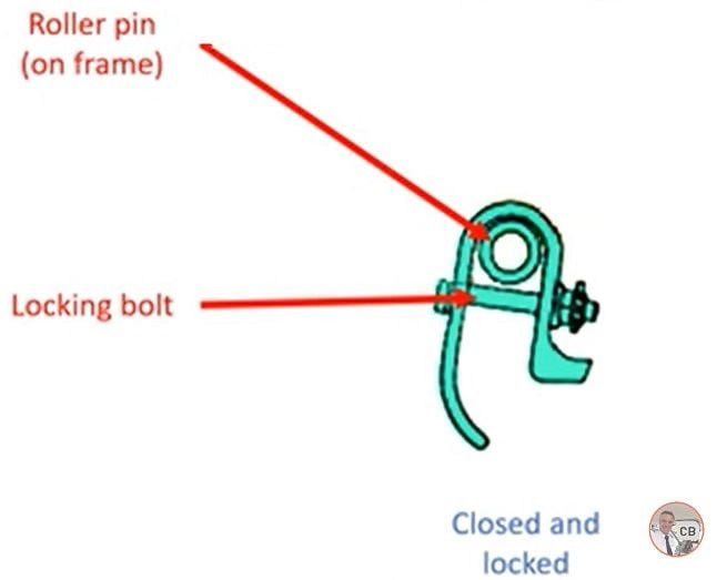
Diagram thanks to Chris Brady
Last edited by DaveReidUK; 9th Jan 2024 at 19:55. Reason: added diagram
Join Date: May 2011
Location: U.S.
Posts: 84
Likes: 0
Received 0 Likes
on
0 Posts
And what exactly are we looking at in Mudman's first three photos - are those bolts protruding out of the fuselage in his marked positions 1 & 2 under NTSB's plastic?? Can't be - nothing protudes below the outside of a closed plug, does it, or even below a part open one ... must be another trick of the light ...
And finally, I am with Mudman on his astounding last pic of the hinge on an inspected United aircraft - what design feature stops the hinge collar securing bolts from coming loose?
S&T
And finally, I am with Mudman on his astounding last pic of the hinge on an inspected United aircraft - what design feature stops the hinge collar securing bolts from coming loose?
S&T
Last edited by lateott; 9th Jan 2024 at 19:34. Reason: Typo
Join Date: May 2011
Location: U.S.
Posts: 84
Likes: 0
Received 0 Likes
on
0 Posts
I'm way out of depth in the detailed mechanical discussion going on here, but it does appear that there's going to need to be a modification, which surely will mean design, testing, approval, manufacture, installation, etc before the type is allowed back in the air. Which is yet another disaster for the Max programme.
What are the chances, while all this is going on, of replacing short/medium term the "plugs" with a proper, already certified door at this position, like the high density users who are carrying on unrestricted, and doing without a few seats in the interim.
What are the chances, while all this is going on, of replacing short/medium term the "plugs" with a proper, already certified door at this position, like the high density users who are carrying on unrestricted, and doing without a few seats in the interim.
Join Date: Apr 2019
Location: Sweden
Posts: 13
Likes: 0
Received 0 Likes
on
0 Posts
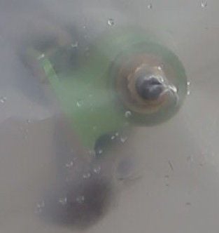
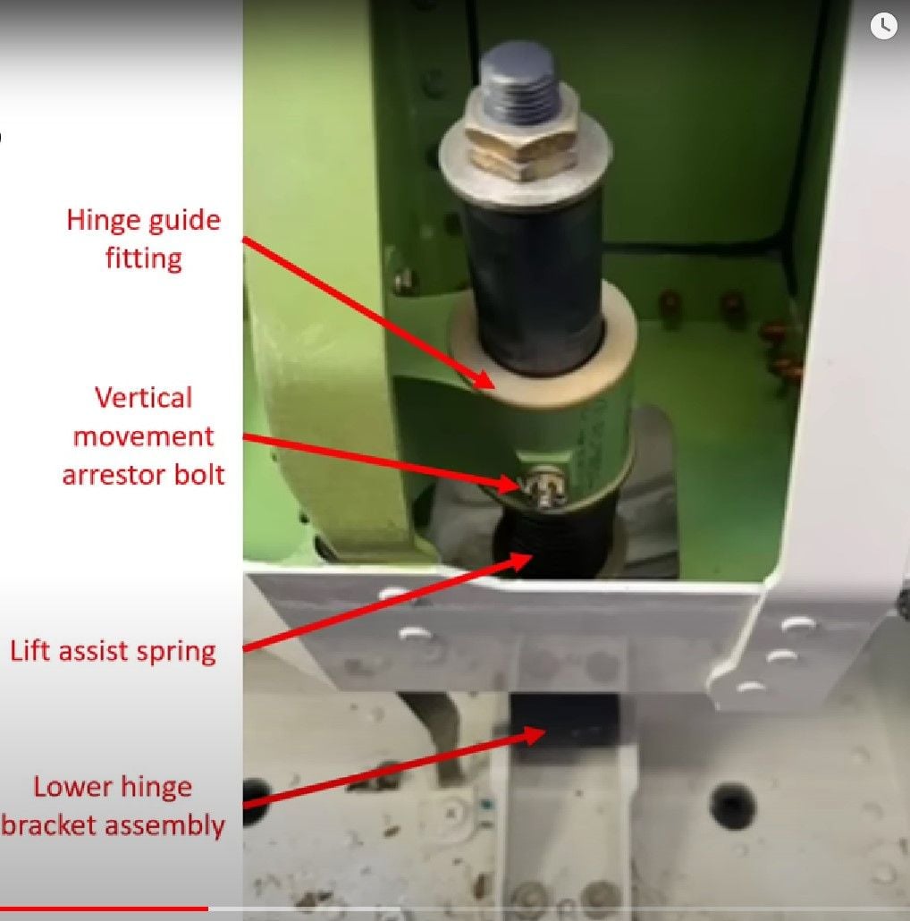
I was wrong about the locking pin (Vertical Movement Arrestor Bolt) still being in place, after seeing better images I agree that the it appears gone and the Hinge Guide Fitting is stopped by the end plate of the Hinge Shaft, thanks to DaveReidUK and lateott for clarifying this (and also good picture with terminology).
However, my main point is the important fact that the Hinge Guide Fitting (HGF) is not attached to the door frame, and that it appears undamaged at the attachments. Furthermore, this exact problem was found on one of the inspected United aircraft.
See sketch below to illustrate this point. If the HGF is loose from the door frame, that will allow vertical movement of the door regardless of whether all the other bolts are in place or not.
Join Date: Mar 2007
Location: In my head
Posts: 694
Likes: 0
Received 0 Likes
on
0 Posts
Originally Posted by me
And what exactly are we looking at in Mudman's first three photos - are those bolts protruding out of the fuselage in his marked positions 1 & 2 under NTSB's plastic??
Join Date: Dec 2014
Location: Somerset
Posts: 40
Likes: 0
Received 0 Likes
on
0 Posts
Hinge Assembly
In Mudman's photos from NTSB (thanks to him by the way for discovering they had such resolution!), you see the ends of the folded-outward hinge shafts along with their bolts and washers. This is as if you were looking from the top down at the hinge/bracket assembly in an installed door plug. Position 2 has the hinge guide fitting (collar/bracket) with the hexagonal nuts at the end, Position 1 only has the shaft with its washer and hexagonal nuts at the end.
Alternative views from anyone with better eyesight or imagination welcome.
Last edited by Europa01; 9th Jan 2024 at 21:05.
I can't recall ever torquing a castle nut - Sod's Law dictates that when you reach the specified torque, none of the slots on the nut will line up with the hole in the bolt for the split pin, so you would then have to tighten the nut past the recommended torque (not a good idea) or back it off (in which case, why bother with the torque wrench at all?).
It was fairly easy to show that depending on how you held the torque wrench/spanner combination you could get wildly different applied torques to the bolt. Even no torque at all. This discovery caused a certain amount of consternation in de Havilland production.
Another technique I have seen (from Deutz diesel cylinder head bolts if I remember) is to torque the bolts to a certain (small) torque then apply a certain number of turns. That probably makes it easier to line up locking fittings.
(SLF engineer)