Alaska Airlines 737-900 MAX loses a door in-flight out of PDX


Join Date: Jan 2024
Location: Seattle
Posts: 1
Likes: 0
Received 0 Likes
on
0 Posts
Agreed. I don't see how the door can slide upwards unless the upper bolts were missing, OR, if there's a tolerance issue with the amount of roller engaging in the slot. What if the edge of the bolt wasn't enough to hold the roller in place? Could be because incorrect diameter bolt was used, or width of frame was larger than expected / designed. Once they find the door they will know (obviously) whether the bolts are there (or not) and if they are of the correct size.
Last edited by RLB1; 8th Jan 2024 at 01:36.

Join Date: Sep 2009
Location: uk
Posts: 32
Likes: 0
Received 0 Likes
on
0 Posts
I have read all 282 posts. I'm going for option c) "omitting the bolts"
If that is the case, either Boeing and Spirit will blame each other as to who is responsible for sending the aircraft to the customer. Or they will both learn from this.
If that is the case, either Boeing and Spirit will blame each other as to who is responsible for sending the aircraft to the customer. Or they will both learn from this.
Would a routine external inspection have shown if the plug had moved from the fully closed position but not yet released from the guides?
Join Date: Apr 2008
Location: BOS
Posts: 6
Likes: 0
Received 0 Likes
on
0 Posts
If I could post photos I would, but look at the post immediately below yours and compare with the photos upthread of correctly-fitted plugs _and_ doors. In both cases the frame of the door or plug is secured to the aircraft with what appear to be twelve bolts/large screws installed from the inside. These match with fairly sturdy protrusions from the fuselage and (to the untrained eye) are pretty hefty mechanisms for holding the plug (or the door frame) in place. (To be clear, look at spornrad's picture -- the things at the top and bottom)
In the picture of the accident aircraft, you can see the four top protrusions from the fuselage (they're pretty obvious) and they appear to have metal in them where the bolts would be. But the frame is completely absent, along with the first parts of those screws/bolts, leaving the rest attached to the fuselage.
It's entirely possible I'm missing something, please (and I'm serious) tell me why I'm wrong.
Join Date: Apr 2015
Location: Under the radar, over the rainbow
Posts: 790
Likes: 0
Received 0 Likes
on
0 Posts
And if it is true that the plug was removed and reinstalled during final assembly at Renton, even trying to shift responsibility would be pointless.
If I could post photos I would, but look at the post immediately below yours and compare with the photos upthread of correctly-fitted plugs _and_ doors. In both cases the frame of the door or plug is secured to the aircraft with what appear to be twelve bolts/large screws installed from the inside. These match with fairly sturdy protrusions from the fuselage and (to the untrained eye) are pretty hefty mechanisms for holding the plug (or the door frame) in place.
In the picture of the accident aircraft, you can see the four top protrusions from the fuselage (they're pretty obvious) and they appear to have metal in them where the bolts would be. But the frame is completely absent, along with the first parts of those screws/bolts, leaving the rest attached to the fuselage.
It's entirely possible I'm missing something, please (and I'm serious) tell me why I'm wrong.
If they were bolts through them, nobody would have to worry about the door opening, ever.
I'm pretty sure that's been covered before, more than once.
Join Date: May 2011
Location: U.S.
Posts: 84
Likes: 0
Received 0 Likes
on
0 Posts
If I could post photos I would, but look at the post immediately below yours and compare with the photos upthread of correctly-fitted plugs _and_ doors. In both cases the frame of the door or plug is secured to the aircraft with what appear to be twelve bolts/large screws installed from the inside. These match with fairly sturdy protrusions from the fuselage and (to the untrained eye) are pretty hefty mechanisms for holding the plug (or the door frame) in place. (To be clear, look at spornrad's picture -- the things at the top and bottom)
In the picture of the accident aircraft, you can see the four top protrusions from the fuselage (they're pretty obvious) and they appear to have metal in them where the bolts would be. But the frame is completely absent, along with the first parts of those screws/bolts, leaving the rest attached to the fuselage.
It's entirely possible I'm missing something, please (and I'm serious) tell me why I'm wrong.
In the picture of the accident aircraft, you can see the four top protrusions from the fuselage (they're pretty obvious) and they appear to have metal in them where the bolts would be. But the frame is completely absent, along with the first parts of those screws/bolts, leaving the rest attached to the fuselage.
It's entirely possible I'm missing something, please (and I'm serious) tell me why I'm wrong.
Join Date: May 2011
Location: U.S.
Posts: 84
Likes: 0
Received 0 Likes
on
0 Posts
Yes, and maybe not a bad idea for some redundancy in securing the plug option...
Join Date: Dec 2014
Location: Somerset
Posts: 40
Likes: 0
Received 0 Likes
on
0 Posts
Locking Mechanism
Thanks for that - I hadn't seen the latest video, which makes everything clearer. Mea culpa.
I note that all 4 bolts are retained by castle nuts and cotter pins (more usually known as split pins). Had those been correctly assembled, I can't see any way that the door plug could have let go. Incorrect assembly could be any of:
a) omitting the split pins
b) omitting the nuts and therefore the split pins
c) omitting the bolts and therefore the nuts and split pins
at any or all of the 4 bolt locations.
Any thoughts?
If the stop bolts on one or both of the hinge pillars were not present then the lift assist springs would be continuously trying to lift the plug and disengage the roller pin from the guide track. If the stop bolts on the guide tracks were effective then this shouldn�t matter but the departure of the plug suggests that they were not. From the photos it is difficult to gauge the angle of the guide tracks but it might be possible that the internal pressure force on the plug would result in an upward component adding to the load on the roller pin?
Thoughts?

Acknowledge Chris Brady�s info.
Last edited by Europa01; 8th Jan 2024 at 07:25. Reason: Addition of Photo
Join Date: Apr 2015
Location: Under the radar, over the rainbow
Posts: 790
Likes: 0
Received 0 Likes
on
0 Posts
Not being sufficiently familiar with doors, or plugs, like this one, I thought the same thing at first. But those are not bolts or screws, they are "stop fittings and stop pads." The latest video by Chris Brady answers most of the most relevant questions about the construction of the door plug. It's posted above, most recently at #281.
1. Incorrect size bolts or inferior bolt material.
2. Some portion of the door structure was damaged during installation by using an unapproved procedure (e.g., AA 191 or UAL 811)
It's now being reported that the FAA are insisting that even aircraft that have undergone the AD inspection and been cleared, should still be grounded pending additional maintenance action:
FAA says some Boeing 737 Max 9 planes may need maintenance to prevent another blowout
FAA says some Boeing 737 Max 9 planes may need maintenance to prevent another blowout
This is sort of old news getting recycled as new. It was reported yesterday that Alaska had 18 MAX 9s that had recently returned from heavy maintenance, which included a detailed inspection of the plug doors. Based on this action, Alaska allowed those aircraft to return to service (see my post #101). This was before the AD. As far as the additional maintenance, as far as I know, the FAA has yet to specify any of the specific actions necessary to return the MAX 9s to service.
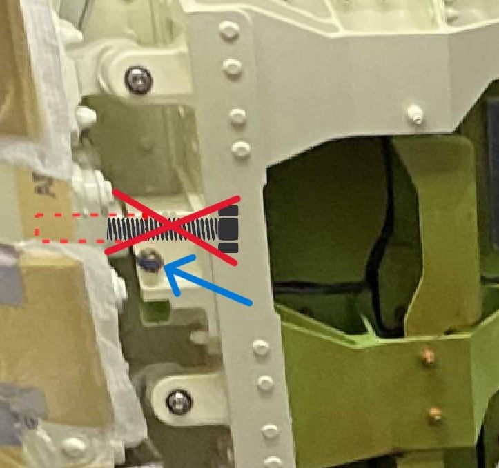
Here is what I see from an engineering viewpoint.
The first image shows the stub guide location and due to its length, guides the door up and out. This would be how it functions when the extra exit door is installed.

Where the stub guide would be
In the second photo taken from the incident aircraft, we can see the stub guide indicated by the red arrow,. The blue arrow shows it has a threaded hole in it and that is where we would expect to see a locking bolt for when a permanent plug door is in place.
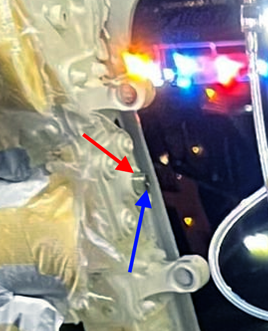
Shows the stub guide in place on incident aircraft
The third image shows where and how I would see the locking bolt in situ if it were ever installed.
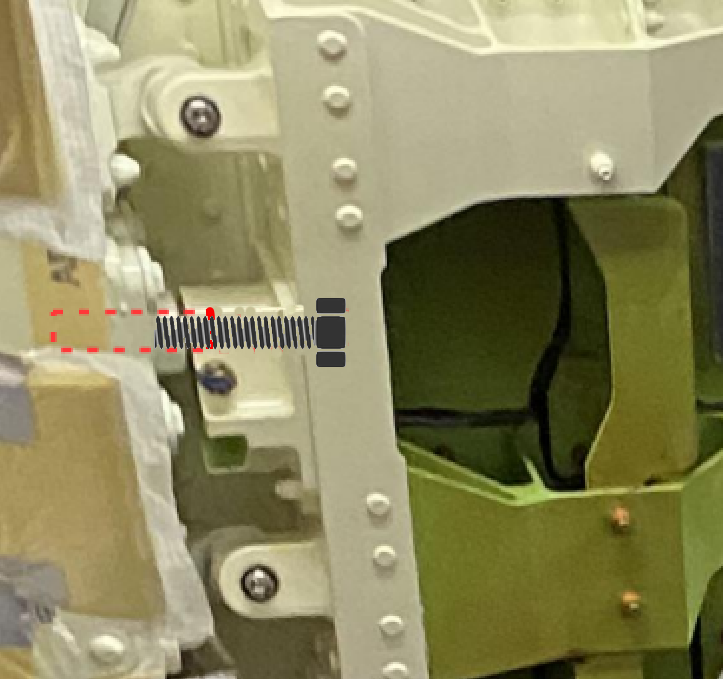
shown with locking bolt
,
To me it seems the locking bolts were never installed.
The first image shows the stub guide location and due to its length, guides the door up and out. This would be how it functions when the extra exit door is installed.
Where the stub guide would be
In the second photo taken from the incident aircraft, we can see the stub guide indicated by the red arrow,. The blue arrow shows it has a threaded hole in it and that is where we would expect to see a locking bolt for when a permanent plug door is in place.
Shows the stub guide in place on incident aircraft
The third image shows where and how I would see the locking bolt in situ if it were ever installed.
shown with locking bolt
,
To me it seems the locking bolts were never installed.
Join Date: May 2011
Location: U.S.
Posts: 84
Likes: 0
Received 0 Likes
on
0 Posts
Here is what I see from an engineering viewpoint.
The first image shows the stub guide location and due to its length, guides the door up and out. This would be how it functions when the extra exit door is installed.
Where the stub guide would be
In the second photo taken from the incident aircraft, we can see the stub guide indicated by the red arrow,. The blue arrow shows it has a threaded hole in it and that is where we would expect to see a locking bolt for when a permanent plug door is in place.
Shows the stub guide in place on incident aircraft
The third image shows where and how I would see the locking bolt in situ if it were ever installed.
shown with locking bolt
,
To me it seems the locking bolts were never installed.