


787 electrical system - variable frequency generators?

Thread Starter
Join Date: Jul 2008
Location: U.S.
Posts: 41
Likes: 0
Received 0 Likes
on
0 Posts
787 electrical system - variable frequency generators?
So how is an aircraft electrical system like the 787 able to be powered by these large, variable frequency AC generators without a constant speed drive (CSD)? My understandings of AC electrics was that motors driven by AC power need stable frequency in order to operate properly and for longevity. Why do "relatively" modern aircraft like the 777 bother with the weight of complexity of constant speed drives (CSDs) and an aircraft like the 787 doesn't need CSDs?

So how is an aircraft electrical system like the 787 able to be powered by these large, variable frequency AC generators without a constant speed drive (CSD)? My understandings of AC electrics was that motors driven by AC power need stable frequency in order to operate properly and for longevity. Why do "relatively" modern aircraft like the 777 bother with the weight of complexity of constant speed drives (CSDs) and an aircraft like the 787 doesn't need CSDs?
The 777 also uses VSCF - but much lower power output (20 KVA on each engine, if memory serves) for 'backup power', as compared to the 150 KVA output of the constant speed IDG.
The 787 has a very complex power generation and distribution system. It uses large capacity, liquid cooled transformers to convert the frequency wild AC from the generators to square wave +/-270v DC . This drives all the big motors such as hydraulic pumps, cabin air compressors etc. It's difficult to describe without diagrams. Google may help.
Thread Starter
Join Date: Jul 2008
Location: U.S.
Posts: 41
Likes: 0
Received 0 Likes
on
0 Posts
Through Gearlever-
Never heard of square wave DC. These devices that convert the 235V AC variable frequency to "square wave" DC.......what exactly are they? Are they solid state or do they have moving parts? If they get hot enough where they need liquid cooling, then there certainly must be a lot of waste doing the conversion of 235V AC to 270V DC.
I've googled around and found some stuff on the 787 electrics, similar to what gearlever linked (thanks gearlever). Was just wondering if your instructors or manuals had better "insights" to the magic than ours. Our training seems to be transitioning from "build the system" 30 years ago, to now "teach them the minimum." The pendulum has swung to far.
I can't even get a decent 787 electrical schematic. If you guys have one, pass it along!
I'll do my best to explain...I've got time.
The transformers are called CMSCs Common Motor/Starter Contollers. They are solid state, the big ones which are used for driving the engine starter motors etc weigh about 400lbs. There are two independent cooling systems called PECS Power Equipment Cooling System. They pump the cooling fluid around the heat exchangers and through the CMSCs.
As for the square wave DC. Imagine a sine wave with vertical and horizontal componants instead of curved. The vertical represents the voltage. the horizonal represents the duration of the peak voltage. So - imagine you are turning a wheel and you place your hands on the top of the wheel and push it along - from a standing start when the engine starter is engaged, the motor needs a big slow push so the horizontal line of your square wave (value +270vDC) is quite long and could last for say half a second, until the motor has rotated 180 deg then the square wave reverses to (-270vDC) and gives a slightly shorter 'push' on the motor in the other direction - your hands are now at the bottom of the wheel and you are now 'pulling' it back towards you as it rotates on it's axel - this flip flopping of the +-270vDC continues with shorter and shorter horizontal componants to the square wave until the motor is up to speed.
This is how it was explained to me (and a bunch of other) mechanical trained LAEs during the Boeing course. Brian from Hawaii, thank you very much by the way.
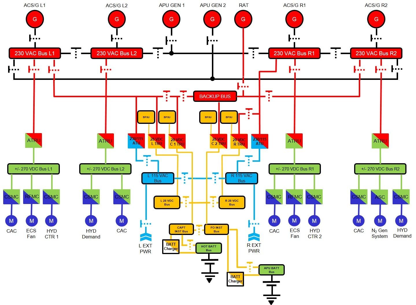
Here's a few links. This diagram isn't completly accurate but it illustrates the general arrangement.
CMSC
Square Wave
The transformers are called CMSCs Common Motor/Starter Contollers. They are solid state, the big ones which are used for driving the engine starter motors etc weigh about 400lbs. There are two independent cooling systems called PECS Power Equipment Cooling System. They pump the cooling fluid around the heat exchangers and through the CMSCs.
As for the square wave DC. Imagine a sine wave with vertical and horizontal componants instead of curved. The vertical represents the voltage. the horizonal represents the duration of the peak voltage. So - imagine you are turning a wheel and you place your hands on the top of the wheel and push it along - from a standing start when the engine starter is engaged, the motor needs a big slow push so the horizontal line of your square wave (value +270vDC) is quite long and could last for say half a second, until the motor has rotated 180 deg then the square wave reverses to (-270vDC) and gives a slightly shorter 'push' on the motor in the other direction - your hands are now at the bottom of the wheel and you are now 'pulling' it back towards you as it rotates on it's axel - this flip flopping of the +-270vDC continues with shorter and shorter horizontal componants to the square wave until the motor is up to speed.
This is how it was explained to me (and a bunch of other) mechanical trained LAEs during the Boeing course. Brian from Hawaii, thank you very much by the way.
Here's a few links. This diagram isn't completly accurate but it illustrates the general arrangement.
CMSC
Square Wave
Last edited by TURIN; 1st Apr 2020 at 09:58.
I think part of the confusion is calling it square wave DC. The regular stuff that comes out of the wall outlets in my house is sine wave AC. If you change the wave shapes from smooth peaks to squared-off plateaus, I'd think you'd get square wave AC. (As as long as the plateaus alternate on opposite sides of zero; if they didn't, it seems like it would just be plain old DC.)
Cunning Artificer
Join Date: Jun 2001
Location: The spiritual home of DeHavilland
Age: 76
Posts: 3,127
Likes: 0
Received 0 Likes
on
0 Posts
The ATRUs produce both plus and minus 270 V DC outputs. The Motor Controllers modulate the duration for which the dc power from each output is alternately applied to the motors - with longer pulses at the start reduced to shorter and shorter pulse width as the motor accelerates.
By the way, the additional weight of the electrical components is counter-acted by there being no need for a separate starter motor, start control valve, pneumatic supply - or even a (notoriously unreliable) pneumatic system at all. Hallelujah!
Now for the hydraulics, Heh! Heh!
By the way, the additional weight of the electrical components is counter-acted by there being no need for a separate starter motor, start control valve, pneumatic supply - or even a (notoriously unreliable) pneumatic system at all. Hallelujah!
Now for the hydraulics, Heh! Heh!


Thread Starter
Join Date: Jul 2008
Location: U.S.
Posts: 41
Likes: 0
Received 0 Likes
on
0 Posts
All through Vessbot, thanks!
Great schematic Turin. That's the best I've seen. Does anyone know if the 230V AC system is powered when external AC power is plugged in, like at the gate, with the engines and APU not running? If the 230V AC system can be powered by external AC power plugs, do those two AC transformers that convert 230V AC to 115V AC for the L&R AC busses also convert the 115V AC back to 230V AC when 115V AC is the only power available through external power?
As a motorhome owner, I've heard of square wave "sine waves" as cheap inverters on motorhomes (among other uses like in personal pleasure boats) take the motorhome's house batteries (12V DC) and convert their DC power to AC using something other than "smooth" (i.e. pure) sine waves. The use of these cheap converters can hurt appliances (like refrigerators) whose AC motors don't like other than "pure sine" wave AC electricity.
TURIN, you also answered another one of the questions I had in my head after initially reading the 787 electrical system- what in the world were those 3 common motor start controllers (CMSC) needed for? I thought the ATRUs put out "normal" DC electricity (like you'd get from a transformer rectifier in any other jet I've flown). But apparently these ATRUs (as Blacksheep states) aren't putting out "nice" DC voltage like a battery does- it pulses- I assume due to the fact that the ATRUs are receiving wild, plusing, high voltage electricity as an input from the engine and/or APU generators. Therefore, because of the "sort of wild" output from the ATRUs, the CMSCs are needed to properly start (and drive?) these large, DC motors when they're running? Is that correct?
Last edited by waterfalls123; 1st Apr 2020 at 16:46.
Join Date: Jan 2013
Location: Seattle Area
Posts: 263
Likes: 0
Received 0 Likes
on
0 Posts
That was the plan, anyway . . .
Chu Chu
Totally agree, we argued that with the Boeing trainers but they weren't having any of it.
Waterfalls123 That schematic isn't completely accurate, lots of info missing from it so it doesn't tell the whole story. It doesn't show the 3rd ext power socket for a start.
But on the whole, yes, you've got the general idea right.
I think part of the confusion is calling it square wave DC.
Waterfalls123 That schematic isn't completely accurate, lots of info missing from it so it doesn't tell the whole story. It doesn't show the 3rd ext power socket for a start.
But on the whole, yes, you've got the general idea right.
About exciting the field of the alternators, the classic B747 had small magnets in the shaft which were called PMG - permanent magnet generators - to start the excitation process. Not exactly new.

Anyhow, very interesting development on elec power generation on modern airplanes. I still have something to learn (67).
Join Date: May 2008
Location: denmark
Posts: 9
Likes: 0
Received 0 Likes
on
0 Posts
The ATRUs produce both plus and minus 270 V DC outputs. The Motor Controllers modulate the duration for which the dc power from each output is alternately applied to the motors - with longer pulses at the start reduced to shorter and shorter pulse width as the motor accelerates.
Traditional brushed DC motors are in decline due to maintenance.
Brushless DC motors are basically a sort of AC synchronous motors with integrated electronics. There is no need for power electronics in both the CSMC's and the DC motors.

Join Date: Dec 2018
Location: Dundee
Posts: 2
Likes: 0
Received 0 Likes
on
0 Posts
The 787 has a very complex power generation and distribution system. It uses large capacity, liquid cooled transformers to convert the frequency wild AC from the generators to square wave +/-270v DC . This drives all the big motors such as hydraulic pumps, cabin air compressors etc. It's difficult to describe without diagrams. Google may help.