I'll do my best to explain...I've got time.
The transformers are called CMSCs Common Motor/Starter Contollers. They are solid state, the big ones which are used for driving the engine starter motors etc weigh about 400lbs. There are two independent cooling systems called PECS Power Equipment Cooling System. They pump the cooling fluid around the heat exchangers and through the CMSCs.
As for the square wave DC. Imagine a sine wave with vertical and horizontal componants instead of curved. The vertical represents the voltage. the horizonal represents the duration of the peak voltage. So - imagine you are turning a wheel and you place your hands on the top of the wheel and push it along - from a standing start when the engine starter is engaged, the motor needs a big slow push so the horizontal line of your square wave (value +270vDC) is quite long and could last for say half a second, until the motor has rotated 180 deg then the square wave reverses to (-270vDC) and gives a slightly shorter 'push' on the motor in the other direction - your hands are now at the bottom of the wheel and you are now 'pulling' it back towards you as it rotates on it's axel - this flip flopping of the +-270vDC continues with shorter and shorter horizontal componants to the square wave until the motor is up to speed.
This is how it was explained to me (and a bunch of other) mechanical trained LAEs during the Boeing course. Brian from Hawaii, thank you very much by the way.
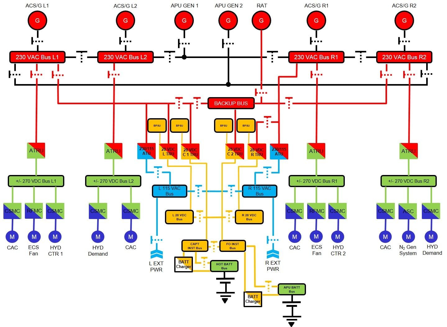
Here's a few links. This diagram isn't completly accurate but it illustrates the general arrangement.
 CMSC
Square Wave
CMSC
Square Wave