


AF 447 Thread No. 7


Joined: Jun 2009
Posts: 451
Likes: 0
From: somewhere
Yaw alternate and Dutch Roll:
Here some 'food for thought' considering Yaw alternate law and dutch roll dampening, extracted from AMM.
AMM 27-90 - ELECTRICAL FLIGHT CONTROL SYSTEM (EFCS)
(1) Normal configuration
----
----
(2) Reconfigurations
(a) Laws and associated functions
1 If the normal control laws are lost:
When the conditions required for keeping the normal control laws are no longer fulfilled, the control laws are reconfigured.
The various degraded law states that are possible are (in flight or upon flare):
// Roll and yaw:
Yaw alternate law
// Pitch:
Nz law (with limited pitch rate and gains)
Vc PROT law (ALPHA 2)
VMO2 law
Pitch direct law
The "Alternate" laws are engaged when the protections related
to the normal laws (ALPHA 1, VM01) are lost.
The "Direct" laws are engaged when the Nz law is lost.
The associated functions available are :
----
----
sideslip estimation (except in alternate 2 law or direct law)
if yaw alternate law, sideslip estimation is changed in Ny body lateral accelerometer.
----
----
2 Yaw alternate law
This FCPC and FCSC law is engaged if the lateral normal law is lost.
Its characteristics are:
- The roll control is direct, an order on the side stick directly commands a deflection, according to a kinematic calculation.
- The yaw control is achieved by the summation of two terms:
. pedal orders
. Dutch roll damping orders (from yaw rate)
In the event of loss of the inertial data from the ADIRUs, the yaw rate data for Dutch roll damping is provided to the FCPC via the rate gyro unit.
If the three FCPCs are lost, the FCSC1 ensures Dutch roll damping, using yaw rate data from the rate gyro unit.
(6) Turbulence Damping Function
(a) General
The purpose of the Turbulence Damping Function implemented in the Electrical Flight Control System is to damp the structural modes induced by atmospheric turbulence.
(b) Architecture
The Turbulence Damping Function consists of two lanes:
1 Longitudinal lane
The longitudinal Turbulence Damping command is computed by the FCPC1 (FCPC2 as a redundancy) as a function of the Nz accelerometer information.
It is added to the normal law command and transmitted to the associated elevator servo-controls.
2 Rear lateral lane
The rear lateral Turbulence Damping command is computed by the FCPC1 (FCPC2 and FCPC3 as a redundancy) as a function of the information of a specific Ny accelerometer located at the rear bulkhead level.
It is added to the normal law command and transmitted to the associated rudder servocontrols.
(c) Specific equipment
- the TURB. DAMP pushbutton switch
- the Ny rear accelerometer.
----
----
(11) Sideslip estimation and Beta target computation
(a) Sideslip estimation
This function is elaborated in the FCPCs in the flight and flare phases. The estimated sideslip is used as an input parameter for the lateral normal law. It is fed to the FMGECs and sent to the DMCs by the FCDCs for display on the PFD.
~o~
Here's a simplified schematic for the 'mechanical' rudder:

 ?
?
Joined: Jun 2011
Posts: 760
Likes: 0
From: france
Is still anybody here ???
@A33Zab
Please, Do You have the answer to Grity's question (AF447 THREAD 7 post #730)
"what did you think is the frequency for the natural roll stability for a330 at this high and speed? "
In my own experience the frequency of the resonance was around 0.4 hz
@MachinBird
The Dutch roll is of much interest : equations have the lowest degree ! That means too that no additional energy is put in the closed loop (very very important).
For any other oscillations, you need to enlower this degree ! Otherwise you have not only inflexion points but inversion points in the response, and that cannot be managed by the pilot in flight.
Last edited by roulishollandais; 22nd January 2012 at 20:08. Reason: spelling MachinBird
Joined: Jun 2009
Posts: 451
Likes: 0
From: somewhere
@roulishollandais:
Could we have a look inside S1, S2, P1, P3
We know what is going in and what is coming out. (FDR traces in--> Yaw damp order + pedal order
and out --> Rudder position --> Yaw rate = Yaw damp order....
If the lateral accel. trace is coming from ADIRU(below cockpit floor) the trace of Ny accelerometers
is missing (Ny accelerometers located aft of bulkhead).
AMM text:
"if yaw alternate law, sideslip estimation is changed in Ny body lateral accelerometer."
"if yaw alternate law, sideslip estimation is changed in Ny body lateral accelerometer."
AMM text:
The estimated sideslip is used as an input parameter for the lateral normal law
The estimated sideslip is used as an input parameter for the lateral normal law
Joined: Jun 2011
Posts: 760
Likes: 0
From: france
roulishollandais:
Quote:
inside S1, S2, P1, P3
A33Zab :
Quote:
We know what is going in and what is coming out.
Sure but I want to know the algorithms
  and logic circuits who are used, and time period of sampling , not only input and output ! I want to see INSIDE
Quote:
inside S1, S2, P1, P3
A33Zab :
Quote:
We know what is going in and what is coming out.
Sure
but I want to know the algorithms and logic circuits who are used, and time period of sampling , not only input and output ! I want to see INSIDE
Joined: Jan 2005
Posts: 2,315
Likes: 10
From: France
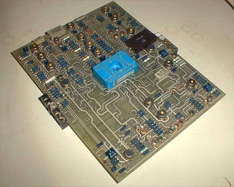
You want to look inside? Here you are...
What you really want is ...
- a full CMM (component maintenance manual),
- a full system block diagram,
- enough system engineering knowledge to interpret the above.....
PS..... OK, that's a Concorde AFCS circuit board.
In those days, the "algoritms" were 'frozen' in op-amps, resistors and capacitors, and the logic was hard-wired using TTL and DT�L logic circuits.
The above photo is an analog control law computing board.
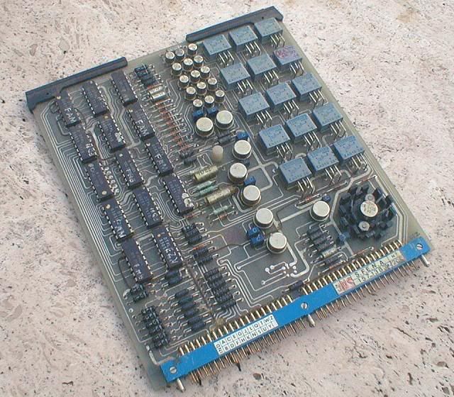
Here's where the logic is being dealt with...
What you really want is ...
- a full CMM (component maintenance manual),
- a full system block diagram,
- enough system engineering knowledge to interpret the above.....
PS..... OK, that's a Concorde AFCS circuit board.
In those days, the "algoritms" were 'frozen' in op-amps, resistors and capacitors, and the logic was hard-wired using TTL and DT�L logic circuits.
The above photo is an analog control law computing board.
Here's where the logic is being dealt with...
Last edited by ChristiaanJ; 4th February 2012 at 20:42.
Joined: Jun 2011
Posts: 760
Likes: 0
From: france
Thank you very much ChristiaanJ ; this Concorde AFCS circuit board (analog control law computing board) is very beautiful; like the Concorde is ! How beautiful it was in the sky ! 
effectively what I still want is ...
- a full CMM (component maintenance manual),
- a full system block diagram,
Despite digital systems overcame on analog system, I am sure that the latter are the best to modelize and control non-linear unstable circuits.
Digitalizing brings many problems at the same time it seemed anything became easy by linearisation, and matrix computing.
Future is ahead !
Joined: Jun 2009
Posts: 451
Likes: 0
From: somewhere
@roulishollandais:
effectively what I still want is ...
- a full CMM (component maintenance manual),
- a full system block diagram
- a full CMM (component maintenance manual),
- a full system block diagram

For test and fail isolation the computer will be connected to an
ATEC Series 6 testbench.
The computer is a modular construction like any modern black box, if a card failed the card is replaced not the failed component on the card itself.
For obvious reasons (e.g. Intellectual property, trade secret, terrorism) a full logical diagram is hidden for the public,
but PJ2 posted a pitch channel logic for A320 a while ago:

FWIW you will not find beancounters in flight operations only, they are well spread over the world and also in the MRO business.
The suppliers of such sophisticated equipment are negotiating - aircraft life term - maintenance contracts (starting with B787)
for their equipment so all technology remain within the vendors company itself.
Joined: Jan 2005
Posts: 2,315
Likes: 10
From: France
If so, CMMs have changed from "my days".
A CMM would provide me with block diagrams, circuit diagrams, circuit board layouts, and yes, pictures like the one you showed, to correlate circuit board references and their physical location in the computer.
But it would also provide me with a full test specification.
I'm afraid you're confusing matters.
The ATEC is an automatic test system that runs an automatic test prgram.
That program does not just appear 'ex nihilo'... it is written on the basis of the original test specification, which can equally well be executed on a manual test bench or a different automatic test system (been there, done that, written ATEC programs....).
That of course depends on what level maintenance you're talking about. But for first/second-line maintenance I agree.
Depends on what you call "the public". In an avionics workshop, I would expect to have access to this kind of information.
Terminology has obviously gone out of the window since "my days". That's not a 'logic' block diagram, but a 'functional' diagram.... and near-useless (except as an intro) to anybody called to maintain the system.
A CMM would provide me with block diagrams, circuit diagrams, circuit board layouts, and yes, pictures like the one you showed, to correlate circuit board references and their physical location in the computer.
But it would also provide me with a full test specification.
For test and fail isolation the computer will be connected to an
ATEC Series 6 testbench.
ATEC Series 6 testbench.
The ATEC is an automatic test system that runs an automatic test prgram.
That program does not just appear 'ex nihilo'... it is written on the basis of the original test specification, which can equally well be executed on a manual test bench or a different automatic test system (been there, done that, written ATEC programs....).
The computer is a modular construction like any modern black box, if a card failed the card is replaced not the failed component on the card itself.
For obvious reasons (e.g. Intellectual property, trade secret, terrorism) a full logical diagram is hidden for the public,
....but PJ2 posted a pitch channel logic for A320 a while ago...
Joined: Jun 2009
Posts: 451
Likes: 0
From: somewhere
@ChristiaanJ:
Oke, we have an insider....
I think so, the specific FCSC CMM consists of 3 parts with a total of 2000+ pages.
Part A: General CMM (more ACMM with IPL and general description, diagrams, assembly etc) but only for casing and interconnecting board.
Part B: The Interconnections in detail
Part C: The ATLAS Test specification and it says - for ATEC series 6 -.
This ATLAS code says more to you than to me and the 'public'.
Anyway, for this type of computer, the required test equipment - today! - is the ATEC series 6.
The boards have their own CMM (I agree: for level 3 workshop) and the software logic and data resides in the OBRMs.
So, with this fragmented CMM information it will not help you to understand whats going on - inside -....
If so, CMMs have changed from "my days".
Part A: General CMM (more ACMM with IPL and general description, diagrams, assembly etc) but only for casing and interconnecting board.
Part B: The Interconnections in detail
Part C: The ATLAS Test specification and it says - for ATEC series 6 -.
This ATLAS code says more to you than to me and the 'public'.
Anyway, for this type of computer, the required test equipment - today! - is the ATEC series 6.
The boards have their own CMM (I agree: for level 3 workshop) and the software logic and data resides in the OBRMs.
So, with this fragmented CMM information it will not help you to understand whats going on - inside -....
Joined: Feb 2009
Posts: 354
Likes: 0
From: Jungles of SW London
ChristiaanJ
These are the boards you showed us on the "Concorde Question?" thread, I think, CJ? Nevertheless, they are good looking boards and bring back a lot of memories, but by gum they look dated now!
A33Zab
Thanks for posting those images - the top ones look just like my CT Renewal Parts manuals but the bottom one - the A320 Pitch channel logic - is 'positioned' rather oddly in my Medical Electronics experience. It is rather crude and a 'level' below most of the block diagrams I use, while being more than a level above the logic diagrams I used to use back in the day.
As CJ puts it:
You couldn't 'chase ones and zeros' through that and I wish I had a pound for every hour I've spent chasing them through page after page of logic diagrams.
These are the boards you showed us on the "Concorde Question?" thread, I think, CJ? Nevertheless, they are good looking boards and bring back a lot of memories, but by gum they look dated now!
A33Zab
Thanks for posting those images - the top ones look just like my CT Renewal Parts manuals
but the bottom one - the A320 Pitch channel logic - is 'positioned' rather oddly in my Medical Electronics experience. It is rather crude and a 'level' below most of the block diagrams I use, while being more than a level above the logic diagrams I used to use back in the day.As CJ puts it:
Terminology has obviously gone out of the window since "my days". That's not a 'logic' block diagram, but a 'functional' diagram.... and near-useless (except as an intro) to anybody called to maintain the system.
Joined: Jun 2011
Posts: 760
Likes: 0
From: france
testing the flying software and automation
@ChristiaanJ
#750
I totally agree with you.
The ATEC Series 6 testbench is a very bad choice who does the pilots blind.
The pilot must be able to understand very quickly what goes wrong in the flight to take the good decision.
The FCSC CMM with 2000 pages is a BABEL ATLAS.
#750
I totally agree with you.
The ATEC Series 6 testbench is a very bad choice who does the pilots blind.
The pilot must be able to understand very quickly what goes wrong in the flight to take the good decision.
The FCSC CMM with 2000 pages is a BABEL ATLAS.
Joined: Jan 2005
Posts: 2,315
Likes: 10
From: France
An ATEC is a huge computer-controlled automatic test bench, used for initial reception of the equipment, and for testing and fault-finding of equipment "thrown off the aircraft as suspect".
I think most pilots have never even seen one......
ATLAS is a specialised programming language for (mostly) avionics and similar aircraft equipment.
Describing ATLAS here in detail is really a bit too much O/T, but any old computer freaks will find some vague similarities with BASIC.
It really is a neat way of writing a full test specification for a piece of equipment in a format that can be understood directly by humans (and even performed on a manual test bench), as well as by fully automatic test equipment (such as the ATEC, but also ATEs from other manufacturers).
The pilot must be able to understand very quickly what goes wrong in the flight to take the good decision.
The FCSC CMM with 2000 pages is a BABEL ATLAS.
I believe the 2000 pages (ours were a bit smaller), but not all of that would be the ATLAS spec.... (unless the ATLAS progs for the individual boards were also included in the CMM, which I doubt), some would be intercon, wiring lists, circuit layouts, diagrams, IPCs, etc.
Anyway, all this is not too relevant, but a nice 'blast from the past'.
Joined: Jun 2011
Posts: 760
Likes: 0
From: france
Hi ChristiaanJ,
[quote=ChristiaanJ]
Testing software or equipment is a very strategic action. ATEC is a good choice for EADS... If something is wrong or missing in ATEC it is the whole responsability if something gets wrong or missing in an EADS aircraft. But, seeing the ATEC advert. it seems to be an commercial product, that B could use too and B will then not be able to see something will get wrong or false in his aircraft or equipment...
The flight engiener is no more in the aircraft. If some hydraulic or electric failure happens caution or warning light and call happen, and a check-list is used. If a software failure happens, nobody knows it in the airplane : the pilots are blinds, get unmotivated, and have behaviour like in AF447.
They get idiots.
2000 pages of Basic : nice to write them, but too big to extract anything useful of such a FBW system for the pilot when things get crazy. 
Before beeing a pilot, I had to organize computer math methods and software in a national research center. After that and due testing, the software was given to twelve regional centers. Some of these softwares concerned human life (dikes). They were running three years (you read well) at the same time that traditional method, without any difference in the results, and without changing anything in the software...
[quote=ChristiaanJ]
Originally Posted by roulishollandais
Originally Posted by roulishollandais 
The ATEC Series 6 testbench is a very bad choice who does the pilots blind.
I don't quite get your point....
An ATEC is a huge computer-controlled automatic test bench, used for initial reception of the equipment, and for testing and fault-finding of equipment "thrown off the aircraft as suspect".
I think most pilots have never even seen one......
Originally Posted by ChristiaanJ
I agree, but that's not the same context....
They get idiots.
Originally Posted by ChristiaanJ
2000 pages (ours were a bit smaller)
Before beeing a pilot, I had to organize computer math methods and software in a national research center. After that and due testing, the software was given to twelve regional centers. Some of these softwares concerned human life (dikes). They were running three years (you read well) at the same time that traditional method, without any difference in the results, and without changing anything in the software...
Joined: Jan 2005
Posts: 2,315
Likes: 10
From: France
roulishollandais,
We seem to be on slightly different wavelengths.....
A CMM is aimed at the maintenance engineer who gets a supposedly faulty piece of equipment dumped on his bench, and has to find and fix the supposed fault, and then recertify the equipment as airworthy.
It is not aimed at either a pilot or (in the olden days) at a flight engineer, who don't necessarily have the specialist engineering background to 'decipher' electronic circuit diagrams or test specifications in a document like the CMM.
They refer to the functional documentation (aircraft flight manuals, etc.).
I think you're confusing testing during development and 'operational' testing....
The ATEC is strictly a production and 'operational' piece of test equipment. It has no relation with the equipment used for software and hardware testing and validation during design and development.
And indeed, ATECs have been sold to other clients, exactly like Honeywell, HP and SFENA ATEs.
We seem to be on slightly different wavelengths.....
A CMM is aimed at the maintenance engineer who gets a supposedly faulty piece of equipment dumped on his bench, and has to find and fix the supposed fault, and then recertify the equipment as airworthy.
It is not aimed at either a pilot or (in the olden days) at a flight engineer, who don't necessarily have the specialist engineering background to 'decipher' electronic circuit diagrams or test specifications in a document like the CMM.
They refer to the functional documentation (aircraft flight manuals, etc.).
Testing software or equipment is a very strategic action.
The ATEC is strictly a production and 'operational' piece of test equipment. It has no relation with the equipment used for software and hardware testing and validation during design and development.
And indeed, ATECs have been sold to other clients, exactly like Honeywell, HP and SFENA ATEs.

Joined: Feb 2011
Posts: 876
Likes: 0
From: Nearby SBBR and SDAM
ATE's, Testability and Maintainability
Hi, ChristiaanJ
Automated and automatic testing was a passion during many years. I faced very interesting challenges designing for adequate testability at Module level (set of PCB's), Board level and Component level(LSI). Your comment on ATE made me ask you something:
Testability is a serious issue in a complex System as you know. A simple example may show why we need strategies to perform an effective test:
Suppose a VERY SMALL memory of just 64 bits. If you test it to all combinations of zeros and ones in the array at 10 Mhz the time required is prohibitive. The solution is to apply a checkerboard pattern, invert it, galloping ones, galloping zeros, all zeros, all ones, etc. And stil you may have a pattern sensitivity.
In a complex machine the Test Engineers use a multitude of Test Strategies at different phases (design phase, prototype testing, etc.)
My question is:
How you compare the ability to test thoroughly an A/C like a current FBW versus e.g. a Concord where Systems were less "Finite State Machines" equipped.
But highly complex and with "feedback loops" that creates formidable challenges when trying to locate for example, an intermittent failure.
I am always concerned with Complex Systems due the "testability issue", so this is the reason of my question to an Engineer from the Concorde era.
It comes to my mind something i heard on A330: To adjust the real Time Clock you have to lower the flaps a little bit.")
Automated and automatic testing was a passion during many years. I faced very interesting challenges designing for adequate testability at Module level (set of PCB's), Board level and Component level(LSI). Your comment on ATE made me ask you something:
Testability is a serious issue in a complex System as you know. A simple example may show why we need strategies to perform an effective test:
Suppose a VERY SMALL memory of just 64 bits. If you test it to all combinations of zeros and ones in the array at 10 Mhz the time required is prohibitive. The solution is to apply a checkerboard pattern, invert it, galloping ones, galloping zeros, all zeros, all ones, etc. And stil you may have a pattern sensitivity.
In a complex machine the Test Engineers use a multitude of Test Strategies at different phases (design phase, prototype testing, etc.)
My question is:
How you compare the ability to test thoroughly an A/C like a current FBW versus e.g. a Concord where Systems were less "Finite State Machines" equipped.
But highly complex and with "feedback loops" that creates formidable challenges when trying to locate for example, an intermittent failure.
I am always concerned with Complex Systems due the "testability issue", so this is the reason of my question to an Engineer from the Concorde era.
It comes to my mind something i heard on A330: To adjust the real Time Clock you have to lower the flaps a little bit.
Last edited by Jetdriver; 27th February 2012 at 08:03.
Joined: Jun 2009
Posts: 451
Likes: 0
From: somewhere
@RR_NDB:
It comes to my mind something i heard on A330: To adjust the real Time Clock you have to lower the flaps a little bit.
Once a day (Flight Phase 9 = after landing) the wing tip brakes are automatically checked, if test fails to initialize for 10 days, this test should be performed by maintenance through MCDU.
When -incorrectly- setting the clock date (manual) you would go beyond those 10 days and trigger the FLAP TIP BRK FAULT and SLAT TIP BRK FAULT messages.
To reset these situation you have to reset the system through CMS AND cycle flaps opposite to the direction when it locked up.
If F/S are in the full up position you only have one way (=DOWN) to go for automatic reset. (and manual reset of the devices becomes necessary when a F/S Up command is required)
To prevent this situation you would lower the F/S a little bit so you can reset (by MCDU) in both directions.
With the GPS clock setting option this would not bring one into this trouble.
Joined: Feb 2011
Posts: 876
Likes: 0
From: Nearby SBBR and SDAM
...you have to lower the flaps a little bit
Hi,
A33Zab
The context of my post was Testability, maintainability, etc.
Fine biz! Some friends also will benefit from your explanation.
Rgds,
A33Zab
Well, nothing to do with a software bug...
Once a day (Flight Phase 9 = after landing) the wing tip brakes are automatically checked, if test fails to initialize for 10 days, this test should be performed by maintenance through MCDU.
When -incorrectly- setting the clock date (manual) you would go beyond those 10 days and trigger the FLAP TIP BRK FAULT and SLAT TIP BRK FAULT messages.
To reset these situation you have to reset the system through CMS AND cycle flaps opposite to the direction when it locked up.
If F/S are in the full up position you only have one way (=DOWN) to go for automatic reset. (and manual reset of the devices becomes necessary when a F/S Up command is required)
To prevent this situation you would lower the F/S a little bit so you can reset (by MCDU) in both directions.
With the GPS clock setting option this would not bring one into this trouble.
Rgds,
Joined: Feb 2011
Posts: 876
Likes: 0
From: Nearby SBBR and SDAM
RHS not recorded
Hi,
A33Zab,
Is this a concern in order to understand reasons of PF persistent NU?
Mismatch between sides are recorded?
BEA published information mentioned this?
If existed a mismatch how we could learn what PF saw?
If this specific point was covered earlier, please inform the link, if possible.
A33Zab,
Is this a concern in order to understand reasons of PF persistent NU?
Mismatch between sides are recorded?
BEA published information mentioned this?
If existed a mismatch how we could learn what PF saw?
If this specific point was covered earlier, please inform the link, if possible.