


Lift Produced Where Wing Transects Fuselage

Join Date: Sep 2002
Location: La Belle Province
Posts: 2,179
Likes: 0
Received 0 Likes
on
0 Posts
"contribution" may be positive or negative, but wing-body doesn't include it, whichever it is. Because it's generally a wind tunnel test thing, and you simply leave the tailplane (and indeed, anything else that takes your fancy) off the model.
Even when the tail IS fitted, wind tunnel models aren't (usually) tested with trimmed tailplanes, but rather with a range of tailplane angles to enable the tail effectiveness to be determined, so there certainly will be cases of both upload and download in most tunnel test sets.


Thread Starter
Join Date: Dec 2010
Location: New York & California
Posts: 414
Likes: 0
Received 0 Likes
on
0 Posts
bearfoil
What are you talking about?
[b]Mad (Flt) Scientist
What about the area of the tailplane that transsects the fuselage?
Aren't there issues with scaling effects?
If you are truly fearful, and fear a trip to "jail", do not wear shoelaces, belts, or ropish jewelry.
"She must have hung herself with her _______".
What about the lumps on her head?
discretion is the better part.........
"She must have hung herself with her _______".
What about the lumps on her head?
discretion is the better part.........
[b]Mad (Flt) Scientist
"contribution" may be positive or negative, but wing-body doesn't include it, whichever it is.
Because it's generally a wind tunnel test thing, and you simply leave the tailplane (and indeed, anything else that takes your fancy) off the model.
Even when the tail IS fitted, wind tunnel models aren't (usually) tested with trimmed tailplanes, but rather with a range of tailplane angles to enable the tail effectiveness to be determined, so there certainly will be cases of both upload and download in most tunnel test sets.
Join Date: Dec 2010
Location: Europe
Age: 88
Posts: 290
Likes: 0
Received 0 Likes
on
0 Posts
What about the area of the tailplane that transsects the fuselage?
Aren't there issues with scaling effects?
Of course there are the normal problems with overall forces and moments affected by the difference between wind tunnel and flight Reynolds Numbers, but they aren't relevant to your original question.
Join Date: Jul 2009
Location: France - mostly
Age: 84
Posts: 1,682
Likes: 0
Received 0 Likes
on
0 Posts
CliveL,
I wonder how the graph you reproduced in your post #18 is produced. Is it just an "artists impression", or perhaps an integration of a measured pressure distribution, or by calculation by CFD?
I wonder how the graph you reproduced in your post #18 is produced. Is it just an "artists impression", or perhaps an integration of a measured pressure distribution, or by calculation by CFD?
Thread Starter
Join Date: Dec 2010
Location: New York & California
Posts: 414
Likes: 0
Received 0 Likes
on
0 Posts
I just thought of something -- why didn't anybody (before area rule was implemented in the traditional sense) think of the idea of flattening the fuselage in between the wings?
It would make the carry-through area more "wing-like" and generate more lift out of the fuselage.
It would make the carry-through area more "wing-like" and generate more lift out of the fuselage.
Join Date: Sep 1998
Location: wherever
Age: 55
Posts: 1,616
Likes: 0
Received 0 Likes
on
0 Posts
Wingbox is an internal structural term. Not applicable in this case.
Jane, the idea was explored in many ways from Parasol Fokker D.VIII and PBY catalina to the flying wings of Horten and others.
There will always be a compromise between structural requirements of the fuselage in terms of strength, volume and shape and the desire to get the most out of the wing.
Jane, the idea was explored in many ways from Parasol Fokker D.VIII and PBY catalina to the flying wings of Horten and others.
There will always be a compromise between structural requirements of the fuselage in terms of strength, volume and shape and the desire to get the most out of the wing.
Thread Starter
Join Date: Dec 2010
Location: New York & California
Posts: 414
Likes: 0
Received 0 Likes
on
0 Posts
FlightPathOBN
I'm not talking about the internal structure. I'm talking about the fuselage section in between the wings. Evidently, depending on the shape of that structure there is a lift contribution in some cases -- I was basically curious if anybody pre area-rule contemplated flattening the fuselage in between the wings to help make it more "wing-like", effectively deriving more lift from the fuselage.
Understand?
FE Hoppy
I didn't know that's why the PBY was designed with a parasol wing, I guess it makes sense though.
I know about flying wings, but many of them had bad handling characteristics in one way or another (bad-stall characteristics for one, sometimes instability, a tendency to wallow in flight) unless there was fuselage in the middle
I thought flying wings were excellent structural designs unless pressurization was an issue as the fuselage frames are effectively the same as the wing's spars and share each other's loads.
If you look at a section of the wingbox, you will see the 'flat' portion you are curious about...
Understand?
FE Hoppy
Jane, the idea was explored in many ways from Parasol Fokker D.VIII and PBY catalina to the flying wings of Horten and others.
I know about flying wings, but many of them had bad handling characteristics in one way or another (bad-stall characteristics for one, sometimes instability, a tendency to wallow in flight) unless there was fuselage in the middle
There will always be a compromise between structural requirements of the fuselage in terms of strength, volume and shape and the desire to get the most out of the wing.
Join Date: Mar 2011
Location: engineer at large
Posts: 1,409
Likes: 0
Received 0 Likes
on
0 Posts
I guess I just considered that entire area, connecting the wings to the fuselage, the center wing box...I guess it is just the center wing...
perhaps a little OT... but the center wing on the 787 is mentioned in wikileaks...
Cable reference id: #08NAGOYA15
perhaps a little OT... but the center wing on the 787 is mentioned in wikileaks...
Cable reference id: #08NAGOYA15
Join Date: Feb 2005
Location: flyover country USA
Age: 82
Posts: 4,579
Likes: 0
Received 0 Likes
on
0 Posts
Jane-DoH:
Several Beechcrafts - Models 18 & 35 e.g. - have a flat fuselage bottom from the wing aft. Don't know what this equates to aerodynamically.
Inverting the thought - The Monocoupe high-wing of the late 20s onward had a flat fuselage top continuous with the wing upper surface. Race pilot Benny Howard deduced this was the reason he "kept seeing the Monocoupe from the wrong end", and stole the idea for his highly successful Mister Mulligan.
I just thought of something -- why didn't anybody (before area rule was implemented in the traditional sense) think of the idea of flattening the fuselage in between the wings?
It would make the carry-through area more "wing-like" and generate more lift out of the fuselage.
It would make the carry-through area more "wing-like" and generate more lift out of the fuselage.
Inverting the thought - The Monocoupe high-wing of the late 20s onward had a flat fuselage top continuous with the wing upper surface. Race pilot Benny Howard deduced this was the reason he "kept seeing the Monocoupe from the wrong end", and stole the idea for his highly successful Mister Mulligan.
My guess on the Catalina is that, intuitively, the area of wing adjacent to the body is pretty well compromised by the slow (relatively) air arriving at it. So to free it from the fuselage gives the centre section a clear view of still air.
The reason for my interest in this thread is that as of about five or so ago, I read that Boeings Kray-hosted CFD could model wings and fuselages, but not both.
My design interest is mainly sailing boats. Our foils have to work both ways up, as it were. Keel mounting in cruising boats is often a grp moulded keel moulded with the hull, and filled with heavy stuff.
Racing yachts and cheap boats have a bolted on keel.
Over the years I have noticed that the moulded grp keels are filleted, bolt-ons are not. Reason being that grp would have to be massive if a hard point were introduced. Fillet distributes the strain more evenly.
So as a young man working at a British Shipbuilders towing tank facilty at the time of Dr Pieter VanOosanen and Ben Lexcen's remarkable "upside-down" and winged keel on Australia III, I got to thinking. At the same time, we were running some submarine tests and used foils to hold it submerged. I wondered if it might be a good idea to separate the keel from the hull entirely because, surely, the water in the region of the non-fillet couldn't be that helpful.
Fast forward again to when I read of Boeings' computer problem.
The New Zealand America's Cup boat was revealed with a 'dillet'. Reverse fillet, so that water arriving at the hull/keel join was encouraged in by the low pressure. Made sense to me, and seemed to work for them.
Back to 'planes. Fillet might add strength if it were integral with the body/wing skins, but I suspect that it's not really.
So why fillet, and why not dillet on the top side? Get the air speeded up a bit.

Different boat altogether.
http://mox.polimi.it/fulltext.php?file=10-2007.2007.pdf
Page 11 shows what I'm talking about, but at the bottom end where the lifting foil meets tha ballast bulb.
http://mox.polimi.it/fulltext.php?file=10-2007.2007.pdf
Page 11 shows what I'm talking about, but at the bottom end where the lifting foil meets tha ballast bulb.
Join Date: Mar 2011
Location: engineer at large
Posts: 1,409
Likes: 0
Received 0 Likes
on
0 Posts
I see and understand..
in reality, when the wings are added to the mix, the rollup of the vorticies acts much differently in the composite structure...
I would also note the pure laminar flow of the modelling, which in surface vessel, between the attack angle, currents, and the flow from the wings, isnt very realistic, just as in aircraft modelling software, laminar flow from the wings is simplistic and incorrect.
As soon as the vessel is sideslipping or crabbing, in regards to the current, the upstream surface of the keel will create one vortex, while the shielded side will create a different vortex. Modelling software typically deals with the effect of the current on the vortex, rather that the vortex effect from the current...same for aircraft...
Join Date: Aug 2007
Location: USA
Posts: 278
Likes: 0
Received 0 Likes
on
0 Posts
Jane D'Oh,
You mean like this?
I was basically curious if anybody pre area-rule contemplated flattening the fuselage in between the wings to help make it more "wing-like", effectively deriving more lift from the fuselage.
Join Date: Jul 2009
Location: Not far from a big Lake
Age: 81
Posts: 1,454
Likes: 0
Received 0 Likes
on
0 Posts
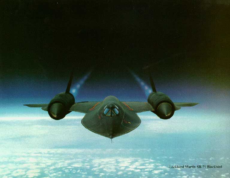
On supersonic aircraft such as the SR-71 and F-18, my understanding is that lift is generated by every square inch of the aircraft planform during supersonic flight, rather than just the wing area which is more the case during subsonic flight.
Since the Aerodynamic center moves from its 1/4 cord point back to the Centroid of the Area as you go supersonic, the fuselage area ahead of the wing helps reverse the increase in stability which would tend to increase stabilizer (stabilator) "trim" drag and create excessive nose heaviness.
So the SR-71 example is a lifting fuselage, but it is done for stability reasons which improves aircraft efficiency during supersonic flight.