


QANTAS A380 Uncontained failure.


Joined: Feb 2005
Posts: 4,581
Likes: 0
From: flyover country USA
Lyman:
I assure you that the intact disc (minus the drive arm flange) is only unsupported for a few milliseconds, as the gas pressure drives it aft to a false bearing surface in the LPT inner duct. Now it is once again supported against a fairly low-friction surface, akin to the thrust bearing on your car's crankshaft against which your clutch reacts.
Without a significant torque load (normally the IPC, which is now un-driven and winding down), the IPT has no chance to do anything other than spin up to destruction. Over the decades, I have seen the results of like turbine disconnects; the sequence is always fairly similar, and the results never pretty.
You seem to keep referring to the IP main shaft, but is there any mention of a pertinent shaft defect in this accident report?
...any separation of the Power Arm from the wheel eliminates the cvarriage for the Turbine Disc, via separation, The Disc has no structure left, it is not as if the wheel is inboard, and merely spins on, without bearings.
Without a significant torque load (normally the IPC, which is now un-driven and winding down), the IPT has no chance to do anything other than spin up to destruction. Over the decades, I have seen the results of like turbine disconnects; the sequence is always fairly similar, and the results never pretty.
You seem to keep referring to the IP main shaft, but is there any mention of a pertinent shaft defect in this accident report?

Joined: Aug 2011
Posts: 2,074
Likes: 0
From: Grassy Valley
You seem to keep referring to the IP main shaft, but is there any mention of a pertinent shaft defect in this accident report?....
************************************************************ ***
No, but I am not sure of the direction you want to go. The Shaft did not fail, at least not prior to disintegration. If you look at the section through this space, you see that the Turbine Plane is foreward of the aft bearing (shaft). The attach to the shaft is aft of the bearing plane. So the wheel is connected via a bearing that is remote from its geometrical plane involving a 180 degree return to the Drive Arm. I assume the circumferential fracture is located at the seam between wheel and ARM. The bore of the Wheel at that point is the same diameter as the ARM, does the Wheel slip over the ARM, as it moves "AFT"? Nice trick! Or does it slam into the Stator platform (LPT) which provides some false bearing support? OR, is the circumferential fracture at the aft terminus of the ARM, where it flats to enter the three way join? If the true bearing architecture gives way to a new and "false" support, where is it located? On the Stator? This surface is of course irregular, ad hoc, and incapable of maintaining tolerance that prevent the Wheel from going wildly eccentric, here's why: The bore of the IPT is much larger than the diameter of the IShaft, of course. Unlike a standard slip fit or "Press Join" to an axle (with a keyway, or splines) and without restraint, the wheel cannot maintain any local integrity....
I have searched for the proper schematic, and the usual places are not available, so I do hope I am not remembering the T5, or 7.... So my words are memory based. Bottom line? Can you help me with a better description of this "false bearing". Also, how do the blades remain attached , my opinion is they exited forward as they were pushed out the pine trees by the stator?
Last edited by Lyman; 9th May 2012 at 19:39.
Joined: Feb 2005
Posts: 4,581
Likes: 0
From: flyover country USA
While i have seen an (alleged) cross-section of the T900, I cannot seem to locate it just now. Maybe someone can post a link so I can point out the pertinent features.
But the essential point I'm making is that the uncoupled disc assembly will establish a false bearing INBOARD of the IPT airfoils, so they will remain in place as the disc assembly is driven overspeed.
But the essential point I'm making is that the uncoupled disc assembly will establish a false bearing INBOARD of the IPT airfoils, so they will remain in place as the disc assembly is driven overspeed.
Joined: Dec 2010
Posts: 1,165
Likes: 0
From: Middle America
Lyman,
I only mention the IP shaft because you think it move rearward, somehow separating from the coupling in the compressor section. It did not!
Your quotes:
And,
The IP disc is a smooth bore disc. It fits snuggly around the end of the IP shaft and is held in place by a series of bolts through bolt holes in the power drive arm. If you review the photos in the ATSB reports, the initial failure occurred at the circumferential bolt holes releasing the disc to overspeed. From a design point of view, it is never good to have bolt holes in the area they are in because of the fact bolt holes are built in stress risers. So this was the weakest point once the disc overheated due to the oil fire.
At some point in time, seconds after the power drive arm failure, the disc, still containing the turbine blades, moved rearward, contacting the inner band leading edge of the LPT stage 1 nozzle ring. There was no IP blade to LP nozzle contact to slow the accelerated disc. At this point in time, the disc was highly accelerated, near burst and had stretched so that the "pine tree" features of the disc were enlarged, the turbine blades were now loose. The contact with the LPT nozzle created the metal splatter and then the disc burst. The turbine blades may have come out of the several disc fractured sections in two directions, radially and rearward as the disc departed the engine.
I agree with barit1, this is a classic disc burst, have seen it happen in a test cell, not a pretty sight.
I only mention the IP shaft because you think it move rearward, somehow separating from the coupling in the compressor section. It did not!
Your quotes:
Yet with a shaft transiting aft, the friction can create instant molten metal, whilst the shaft retains integrity
I still suggest that the slowing of the IPC demonstrates the axial migration of the IShaft aft ward into the "stationery parts of the engine" (AD). Integrity of the shaft is required until disintegration of the I Turbine, IMO.
At some point in time, seconds after the power drive arm failure, the disc, still containing the turbine blades, moved rearward, contacting the inner band leading edge of the LPT stage 1 nozzle ring. There was no IP blade to LP nozzle contact to slow the accelerated disc. At this point in time, the disc was highly accelerated, near burst and had stretched so that the "pine tree" features of the disc were enlarged, the turbine blades were now loose. The contact with the LPT nozzle created the metal splatter and then the disc burst. The turbine blades may have come out of the several disc fractured sections in two directions, radially and rearward as the disc departed the engine.
I agree with barit1, this is a classic disc burst, have seen it happen in a test cell, not a pretty sight.
Joined: Dec 2010
Posts: 1,165
Likes: 0
From: Middle America
barit1 & Lyman,
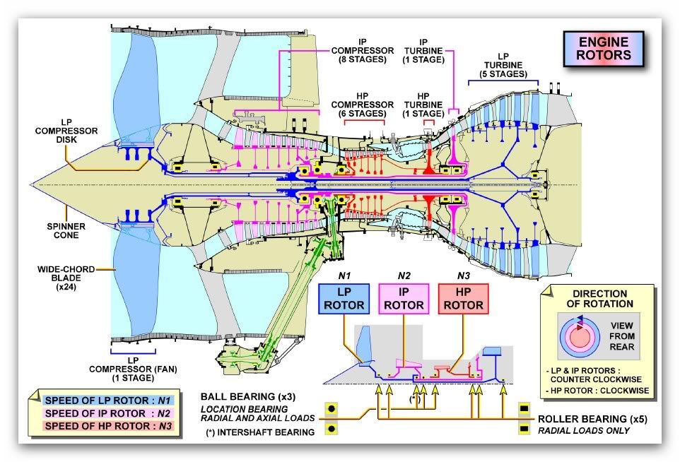
Here is the Trent 900 engine cross-section for your information. Also, one thing I forgot to convey, the disc burst speed I gave was for a normal operating temperatures. With the oil fire, the disc burst speed would be perhaps significantly less...
TD
Here is the Trent 900 engine cross-section for your information. Also, one thing I forgot to convey, the disc burst speed I gave was for a normal operating temperatures. With the oil fire, the disc burst speed would be perhaps significantly less...
TD
Joined: Aug 2011
Posts: 2,074
Likes: 0
From: Grassy Valley
Hi gents. I do not misunderstand your conclusions. Matter of fact, it is very difficult to disagree with them. The Problem.
The drawing is not the one I had in my other computer, which is presently in maintenance. I'd like to condense the crux of my disagreement around the Shaft/Arm/Wheel system.
I caught flack in the first thread for stating that the Wheel and Arm were made up of three parts. I was unclear. Let me start by saying that in this assembly I see three elements. The rim, and blades, the face, or disc, and the Arm, or Drive.
The first design concept I see is the "wraparound" feature of the Arm. Attached outside the bearing load, it performs a 180 to wrap the Shaft as it extends forward to capture the Disc. Is this common? I am familiar only with engines that include rotors inside the "Load frame" iow, attached directly to the shaft. As it is, the Wheel drives a load that is outside the bearing plane "The Attach" So I see potential problems with balance, and resonance.
As barit1 says, and TurbineD agrees, these rotors are of immense strength. Now that is subjective, and since failure is obvious, here, I refer to my earlier comment that due fire, the designed fail (rpm) was reduced, perhaps "substantially" as Turbine D points out.
My intention is to direct the comments (if you agree) toward the method of attachment of the Arm/Wheel, and if you are familiar with any potential pitfalls?
Because although TurbineD disagrees with my "Bell" shaped comment, I think we can see that the Arm and disc create a shape that is similar to bell, mushroom, umbrella, etc. and that this shape must resist a somewhat more complex strain profile than the Wheel/Axle tradition.
Your participation is optional, of course, but I am serious, and believe in addressing some of these concerns; at least one person will gain some knowledge, here. And tht would be me....
ad. For instance, as I say, the load is outside the bearing loadframe. Standard would be within at least two bearings, rather than attached at the end of a shaft supported only one side of the load. A corollary might be "whirl mode", where a great deal of mass and energy is "extended" past a point of support, such that the bearing is stressed in ways that are common to rapidly spinning systems, but ordinarily are suspended between two mounting points....
Please note that according to the drawing, the wheel contacts the LPT platform/stator with its blades prior to the more core oriented partition. So the false bearing would have to "wait" for the wheel to arrive post stator contact?
Isn't this IPT blades contact a design feature, to prevent OverSpeed? Scrub off the blades to prevent a drive surface for the gas path? If so, what failed, in this case?
Is the bearing mount portion of the joint connected to the race? So, can the outer race support the wheel, post separation from Arm? I would offer yes, but there would be a lot of play between the race and the inner surface/drive arm?
Note for comparison the architecture of the HP Rotor, supported on one face by the HP cap bearing, and on the other face by the shaft proper? Here, the loads are functionally within the two bearing planes, and the one sided torsional affect is snubbed?
Similarly, although the Fan is supported outside the bearing run, it has two bearing planes, which provide a 'moment arm' to capture the oddities this disc encounters with the atmosphere, and FOD? Connected as it is to the IPT terminus, and the radius of the bearing system it suggests a very robust carriage for the bulk of the a/c thrust.....
TD, barit1, what would be your opinion on the Drive Arm subject to these torsional anomalies whilst under the climb load of the gas path? Would undue fatigue weaken, and/or heat the system? Mind, the HP bearing and the IP bearing rotate opposite each other, at times with a differential of 20000 rpm.
Last edited by Lyman; 11th May 2012 at 09:12.
Joined: Feb 2005
Posts: 4,581
Likes: 0
From: flyover country USA
First off, my expertise (such as it is) does not include rotor dynamic vibration, but I think having the plane of the IPT disc directly over the aft IP bearing (i.e. zero overhung moment) might have some advantage re whirl mode. But I have never seen this arrangement employed before.
Second, I wonder just how accurate the flowpath detail in Turbine D's cross-section is, especially in the IPT > LPT area. I could see where the inner band of the first LPT nozzle stage could contact the IPT blades at the TE root, perhaps initiating blade failure. This would seem to be in conflict with the failure sequence in the powerplant report. I think Lyman is in agreement here.
Second, I wonder just how accurate the flowpath detail in Turbine D's cross-section is, especially in the IPT > LPT area. I could see where the inner band of the first LPT nozzle stage could contact the IPT blades at the TE root, perhaps initiating blade failure. This would seem to be in conflict with the failure sequence in the powerplant report. I think Lyman is in agreement here.
Joined: Mar 2002
Posts: 4,569
Likes: 1
From: Florida
I could see where the inner band of the first LPT nozzle stage could contact the IPT blades at the TE root, perhaps initiating blade failure. This would seem to be in conflict with the failure sequence in the powerplant report
Do you have a link to the section of the report that you refer?
Typically it is only in a final report which may contain an analyis where critical details are explained and supported.
My read so far is that a local (oil fire) overheat occurred sufficient to release the IPT disk from the compressor load at the drive arm.
This overheat may include only the innermost portions of the turbine disk.
Does the referenced report detail any estimates of disk body material strength from Bore to rim of the disk?.
If not then the strength of the disk may have been only marginally impacted by the oil fire.
Regardless of the answer to my question, the released disk from its drive arm is an important detail in its progression. If it was only completely released in the tangential direction (torque loss only) then it may not have permitted the free disk from moving aft into the aft nozzle vane clusters.
Whether the disk moves aft or not, it would still free wheel up in speed at a very rapid rate while remaining centered about the engine centerline. The tendancy is for it to seek restraint both upon the remaining drive arm/shaft pieces as well as its still intact blade tips against the outer case structure.
The time between the separation from its drive arm and burst would be dependant on several factors
1) the average material strength and average temperature in the compartment (local strength losses due to a localized fire would not be significant as the disk stretches and redistributes its strain)
2) The residual pressure trace across the turbine blades vs time
3) any loss of turbine blades in this stage
Rubbing friction itself against the aft nozzle vanes and between the blade tips and case would be negligible in such an event.
Likewise any false bearing between the blade roots and the aft nozzles would be negligible.
I haven't seen any factual information that suggests that blade to vane contact would be expected in the airfolis for this design.
In the end it's a F=MA over time that assess how far aft the rotor might have moved vs the speed vs time of the free wheeling disk under a decreasing gas load.
If any of the above has been convered already in a report I would be pleased to read it.
Meanwhile I am quite happy with the recommendations provided by this investigation todate (Fault analysis vs quailty control at the manufacturers)
Joined: Aug 2011
Posts: 2,074
Likes: 0
From: Grassy Valley
Lomapaseo,
@ TurbineD...."I assure you that the intact disc (minus the drive arm flange) is only unsupported for a few milliseconds, as the gas pressure drives it aft to a false bearing surface in the LPT inner duct. Now it is once again supported against a fairly low-friction surface, akin to the thrust bearing on your car's crankshaft against which your clutch reacts.
I think TurbineD is correct here, and from the statement, aft migration puts the Turbine's airfoils into the LPT Stator ring, where they are ejected from their slots. This eliminates the ability of the gas path to turn the IPT. The amount of aft migration is failure dependent; but if the circumferential fracture happens about the bolt flange, as he proposed, their is nothing to prevent the drift from continuing well past the Stator into the inner web of the partition.
The HP is receiving fuel in excess of the rpm ratio to flow, (via EEC), I think raw fuel may have entered the cavity to exacerbate the fire post separation, making matters worse. In any event, where do you put the fracture?
Joined: Aug 2011
Posts: 2,074
Likes: 0
From: Grassy Valley
@lomapaseo.....Whether the disk moves aft or not, it would still free wheel up in speed at a very rapid rate while remaining centered about the engine centerline. The tendency is for it to seek restraint both upon the remaining drive arm/shaft pieces as well as its still intact blade tips against the outer case structure.
Noting the room between the bearing box and the drive arm, I would disagree that the Turbine remains centered about its shaft, (the engine's centerline). Gas path pressure and gyroscopic forces work against this type of ad hoc stability, IMHO. So I picture the bore portion as contacting the bearing box in a random and chaotic fashion, not conducive to the Turbine's retention, and destructive of its ability to remain in the engine. This impacts the blades against the platform, and they are lost, immediately.
In any case, do you not agree, that from the drawing, the LPT Stator platform makes first contact as the IPT drifts aft?
Joined: Aug 2011
Posts: 2,074
Likes: 0
From: Grassy Valley
From the drawing, I note a build up of the LPT vanes platform at the area that makes contact first with IPT should it drift aftward. The portion of the IPT that makes contact with this strengthened area is the blade root circle. This in anticipation of wheel release, the design is meant to remove the airfoils in just such an emergency as this explosive burst.
As the design consideration, it demonstrates an improvement in concept, an anticipated mitigation. I suggest that it worked; as bad as this incident appears, if IPT retains its blades any longer than apparent here, the a/ c may have been lost.
As the design consideration, it demonstrates an improvement in concept, an anticipated mitigation. I suggest that it worked; as bad as this incident appears, if IPT retains its blades any longer than apparent here, the a/ c may have been lost.
Joined: Dec 2010
Posts: 1,165
Likes: 0
From: Middle America
Lyman,
Your quote:
No, No, No, that is what you don't want to have happen. What you want to have happen is the turbine blades to stay with the disc which is holding them so that if the disc becomes liberated and if and when it moves back, those turbine blades clash with the turbine nozzle airfoils behind slowing the disc acceleration before it gets to a burst situation. What would then happen would be a bunch of ground up airfoil pieces exiting through the LPT and out the exhaust pipe, but the disc would slow down and remain intact. That is what happened on several older model Trent engines where blade to nozzle contacted prevented disc bursts.
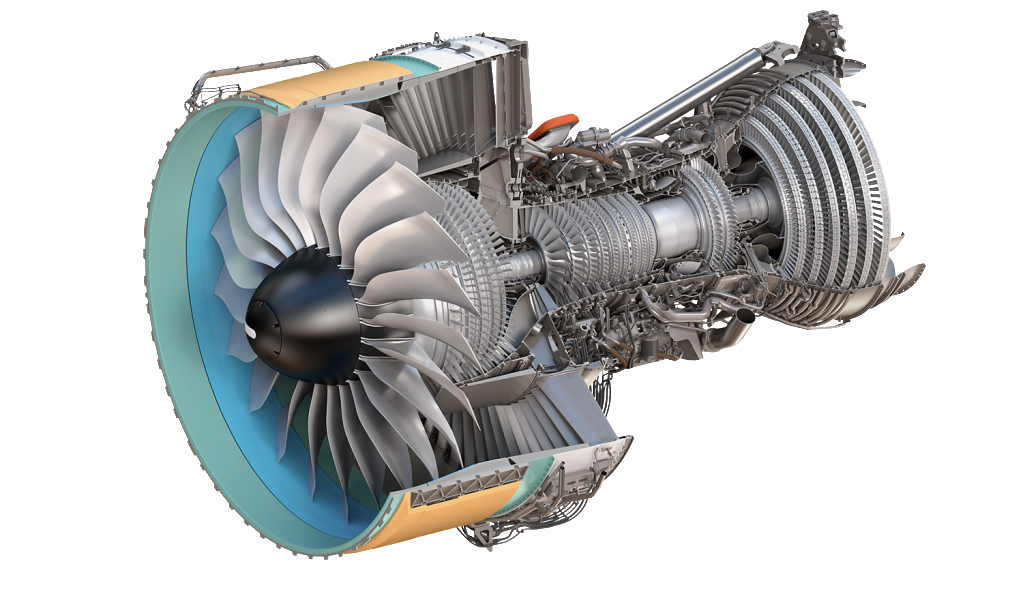
In the case of the Trent 900, when the disc became free, overspeed initiated and when it move back, the contact with the stage 1 LPT nozzle occurred at the disc rim rubbing out the turbine blade retainers thereby creating the potential for the blades to come out and making no airfoil to airfoil contact slowing the disc speed. Remember, there was little damage to the LPT other than the stage 1 LPT nozzle with most of the remnants, disc sections included, exiting radially, not good. I will look again at the photos in the ATSB reports to be sure of this scenario as I am doing it at the moment from recall. In the meantime, look at the GP7200 engine cutaway below.
You will note that if the stage 2 HPT disc (similar position to the IPT disc) became liberated for one reason or another, if it would move back, the turbine blades would clash with the stage 1 LPT nozzle slowing the disc speed. It is an important design feature to inhibit runaway disc speed.
lomapaseo,
All I can say about the intensity of the fire from the burning oil is what the ATSB said in their Interim-factual report:
I do think there is some merit in what you suggest, the disc stayed centered for a short period of time during the acceleration.
Your quote:
From the drawing, I note a build up of the LPT vanes platform at the area that makes contact first with IPT should it drift aftward. The portion of the IPT that makes contact with this strengthened area is the blade root circle. This in anticipation of wheel release, the design is meant to remove the airfoils in just such an emergency as this explosive burst.
As the design consideration, it demonstrates an improvement in concept, an anticipated mitigation. I suggest that it worked; as bad as this incident appears, if IPT retains its blades any longer than apparent here, the a/ c may have been lost.
As the design consideration, it demonstrates an improvement in concept, an anticipated mitigation. I suggest that it worked; as bad as this incident appears, if IPT retains its blades any longer than apparent here, the a/ c may have been lost.
In the case of the Trent 900, when the disc became free, overspeed initiated and when it move back, the contact with the stage 1 LPT nozzle occurred at the disc rim rubbing out the turbine blade retainers thereby creating the potential for the blades to come out and making no airfoil to airfoil contact slowing the disc speed. Remember, there was little damage to the LPT other than the stage 1 LPT nozzle with most of the remnants, disc sections included, exiting radially, not good. I will look again at the photos in the ATSB reports to be sure of this scenario as I am doing it at the moment from recall. In the meantime, look at the GP7200 engine cutaway below.
You will note that if the stage 2 HPT disc (similar position to the IPT disc) became liberated for one reason or another, if it would move back, the turbine blades would clash with the stage 1 LPT nozzle slowing the disc speed. It is an important design feature to inhibit runaway disc speed.
lomapaseo,
All I can say about the intensity of the fire from the burning oil is what the ATSB said in their Interim-factual report:
The investigation has found that the intermediate pressure (IP) turbine disc failed as a result of an overspeed condition, liberating sections of the IP turbine disc that then penetrated the engine case and wing structure. The disc failure was initiated by a manufacturing defect in an oil feed pipe that resulted in a wall thickness reduction in an area that is machined to receive a coarse filter. That section of the oil feed pipe sustained a fatigue crack during engine operations that lead to an internal engine oil fire that weakened the IP turbine disc. In turn, a circumferential fracture was induced around the disc, allowing it to separate from the IP turbine shaft. The unrestrained disc accelerated to critical burst speed. This lead to the No 2 engine failure and subsequent significant penetration damage to the airframe structure and systems.
Joined: Aug 2011
Posts: 2,074
Likes: 0
From: Grassy Valley
I take it then that the airfoils are to be sacrificial? I do not see how the IPT blades can clash with the LPT vanes without transiting the Stator "Platform".
They cannot get there from there. They have to slice through 10 centimeters of platform to access the Vanes. Now that may slow the Wheel, but the blades are lost anyway. If it is as you say, why provide an impediment to instantaneous clash post separation at the ARM? It is not sensible.
I was sure I asked more questions, and I'll stand by the scrub foils for now. May I choose one question to ask? How about the open space between the Bearing box and the bore of the IPT? Sufficient to restrain the IPT and offer a bearing for overspeed? Without allowing aft drift, or Disc eccentrics, wobble?
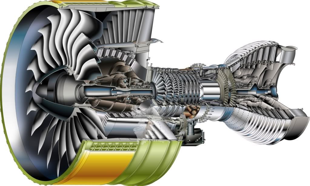
I prefer the TRENT7 pic to the more pedestrian T9drawing......Are they exactly similar? I see that they are not, the foils are pitched the same way. No contra.
They cannot get there from there. They have to slice through 10 centimeters of platform to access the Vanes. Now that may slow the Wheel, but the blades are lost anyway. If it is as you say, why provide an impediment to instantaneous clash post separation at the ARM? It is not sensible.
I was sure I asked more questions, and I'll stand by the scrub foils for now. May I choose one question to ask? How about the open space between the Bearing box and the bore of the IPT? Sufficient to restrain the IPT and offer a bearing for overspeed? Without allowing aft drift, or Disc eccentrics, wobble?
I prefer the TRENT7 pic to the more pedestrian T9drawing......Are they exactly similar? I see that they are not, the foils are pitched the same way. No contra.
Last edited by Lyman; 11th May 2012 at 19:11.
Joined: Aug 2011
Posts: 2,074
Likes: 0
From: Grassy Valley
TD......"You will note that if the stage 2 HPT disc (similar position to the IPT disc) became liberated for one reason or another, if it would move back, the turbine blades would clash with the stage 1 LPT nozzle slowing the disc speed. It is an important design feature to inhibit runaway disc speed."
Come again? I just said that, re: TRENT 900? How does HPT climb through the IPT to get at LPTNozzle? Blade clash is a bad thing for the 9, but ok for the 7?
Come again? I just said that, re: TRENT 900? How does HPT climb through the IPT to get at LPTNozzle? Blade clash is a bad thing for the 9, but ok for the 7?
Last edited by Lyman; 11th May 2012 at 19:08.
Joined: Dec 2010
Posts: 1,165
Likes: 0
From: Middle America
Lyman,
Your quote:
The (GE/Pratt) Engine Alliance GP7200 is a 2 spool engine verses the Trent 900 that is a 3 spool engine. By showing you a cutaway of the GP7200 engine, I wanted you to note only this:
If the stage 2 HPT blade rotor, for whatever reason, moves rearward, disconnected from the shaft, the turbine blades would clash with the stage 1 LPT nozzle airfoils, slowing the disc rotational speed down below that of burst overspeed.
In the Trent 900, if the IP turbine rotor, for whatever reason, moves rearward, disconnected from the shaft, the turbine blades cannot clash with the stage 1 LPT nozzle airfoils to slow the disc rotational speed down below that of burst overspeed.
The difference between the two engines lies in each of their basic designs. The Trent 900 engine is also different from previous (older) Trent designs where blade to nozzle clashing is possible and did occur in several failure instances. So, the Trent 900 is unique in its apparent design and positional relationship between the IP turbine rotor and the LPT stage 1 stator (nozzle). I am not going to speculate as to why the Trent 900 design was developed the way it is.
I don't know how to make this any clearer to you, take your time to understand what is presented, I know it is somewhat complex...
Your quote:
I prefer the TRENT7 pic to the more pedestrian T9drawing
If the stage 2 HPT blade rotor, for whatever reason, moves rearward, disconnected from the shaft, the turbine blades would clash with the stage 1 LPT nozzle airfoils, slowing the disc rotational speed down below that of burst overspeed.
In the Trent 900, if the IP turbine rotor, for whatever reason, moves rearward, disconnected from the shaft, the turbine blades cannot clash with the stage 1 LPT nozzle airfoils to slow the disc rotational speed down below that of burst overspeed.
The difference between the two engines lies in each of their basic designs. The Trent 900 engine is also different from previous (older) Trent designs where blade to nozzle clashing is possible and did occur in several failure instances. So, the Trent 900 is unique in its apparent design and positional relationship between the IP turbine rotor and the LPT stage 1 stator (nozzle). I am not going to speculate as to why the Trent 900 design was developed the way it is.
I don't know how to make this any clearer to you, take your time to understand what is presented, I know it is somewhat complex...
Joined: Aug 2011
Posts: 2,074
Likes: 0
From: Grassy Valley
So let me ask you then re: your response. Does the GP have an IPT turbine that is affixed with the same architecture as the T9? Because if it is fit on to the shaft via keyway or splines, the overspeed would happen , should the key(s) shear, or the splines grind smooth. It is the false bearing that interests me.
So one question then. Can you show me the false bearing locus? Because any aft movement at all of the IPT in the TRENT puts the aerofoil ring into the LPT Stator. Isn't that accomplishing the same thing as the GE in wheel loss? Design aside, I see no room for false bearing to establish, without IPT/LP1Nozzle conflict. At 500 pounds, the IPT would take out anything in its way, and I do not see how you propose the Bearing box to contain it to capture gas path, and resultant spin up? The relative bore/diameter of this 'new' bearing/system does not look like it is up to keeping the Wheel from axial drift, and/or blade clash with LPT Stator.
I do not see the LPT vanes at all in the GE/PRATT.
Last edited by Lyman; 11th May 2012 at 21:01.
Joined: Dec 2010
Posts: 1,165
Likes: 0
From: Middle America
Lyman
Your quote:
The GP7200 engine does not have an IPT rotor, it is a two spool engine and the HPT consists of two rotors, Stage 1 and Stage 2.
Your quote:
Perhaps this view of the GP7200 will enable you to see the Stage 1 LPT nozzle in relationship to the Stage 2 HPT rotor.
Your quote:
I don't think it does on the Trent because of the angular lean of the Stage 1 LPT vane, refer back to the Trent cross section. The impingement between the two on the Trent is close to the blade root and disc pine tree holding the blades and the inner band extension of the Stage 1 LPT nozzle ring. If you look at the recovered parts photographed in the ATSB report, you can note 2 items of interest. On the recovered LPT vane segment, the inner band is gone. Also, the turbine blade retainers on the recovered portion of the IPT disc are all missing. So you have relatively one smooth surface contacting another relatively smooth surface. Beyond, these observations, nothing more can be said with any certainty. Even with all the recovered parts, lab analysis, etc., plus the assistance of the engine designer and builder, it is difficult to reconstruct the minuscule details of exactly what happened in the few seconds following the release of the IPT rotor disc and blades to the degree you are attempting to without the complete data the ATSB possesses and the knowledge RR has on this engine.
Your quote:
Does the GP have an IPT turbine that is affixed with the same architecture as the T9?
Your quote:
I do not see the LPT vanes at all in the GE/PRATT.
Your quote:
Because any aft movement at all of the IPT in the TRENT puts the aerofoil ring into the LPT Stator. Isn't that accomplishing the same thing as the GE in wheel loss?
Joined: Aug 2011
Posts: 2,074
Likes: 0
From: Grassy Valley
TurbineD
As always, thanks for your patience and expertise. A quote from you....
You will note that if the stage 2 HPT disc (similar position to the IPT disc) became liberated for one reason or another, if it would move back, the turbine blades would clash with the stage 1 LPT nozzle slowing the disc speed. It is an important design feature to inhibit runaway disc speed.
In either engine, the Power Turbine, (IPT in the TRENT, and HPT2 in G/P) send the gas path into the (stationery) nozzle of the engine's LP (turbine) cavity. In the G/P, the vanes are elongated and occupy the plane directly behind the blades of the Power Wheel. The Trent's Vanes appear shorter in length, and are arranged at some distance aft of the preceding rim of the STATOR. This means, as you say, that blade clash will not occur instantly, and the effacement in aft drift occurs with two smooth surfaces, rather than Blade/Blade.
I am speculating as to design. To me, it (TRENT9) represents a sequential approach to Disc runaway. The Wheel is slowed, and borne temporarily at Blade roots/Stator platform, (your "On the recovered LPT vane segment, the inner band is gone. Also, the turbine blade retainers on the recovered portion of the IPT disc are all missing.") So you have relatively one smooth surface contacting another relatively smooth surface. This wipes the retainers, and the blades loosen in the IPT. As the blades begin to depart the wheel, the IPT captures less of the power of the gas path, and the blades shred, to fill the cavity with shrapnel. This shrapnel, I see as a benefit to further loss of blades and resultant loss of rpm. As the IPT travels further back, the Platform degrades into more robust areas of the Platform, and eventually the Blades/Vanes efface.
The IPT, off arm, does not have a solid support at the bearing box, though it does have concentric structures post fracture. This allows an eccentric braking action, though the vibration and noise must be extreme.
At the last, the IPT foils (if any are left) scrub the Vanes of the LPT nozzle, removing the last of them.
As you point out above, blade/blade is the G/P approach to arrestment, RR similar, but with a primary contact at blade roots, Stator platform. Again, I believe that the desire is to slow the wheel, but I would add that equally important is to defeat the gas path mechanically, a fuel cut is not possible in this time sequence.
So I can only say that the approach is different in the 900, but to me represents a step ahead of that taken by GE/PRATT.
I do not discount the overspeed, but I note that you agree the design limit for separation of the wheel into three parts may have happened at lower than maximum rpm for integrity. Yes?
Thanks again
Last edited by Lyman; 13th May 2012 at 21:22.
Joined: Mar 2011
Posts: 11
Likes: 0
From: La Rochelle
Turbine D is your man here. He should be working for the ATSB.
Lets not forget that this was a T972 on very heavy work cycles esp out of LAX ro Oz. RR made a severe error in an oil pipe bore. Qantas are persuing them in court.
This engine was not a T970 or a T1000.
Turbine D is one of the very few people who had the quals and tactile experience to assess this engine failure.
And as for No. 1 engine running on a for a full hour .. what can you say..God was with them.