


Twin Otter Fuel System Question

Thread Starter
Joined: Oct 2010
Posts: 3
Likes: 0
From: Canada
Twin Otter Fuel System Question
Hi,
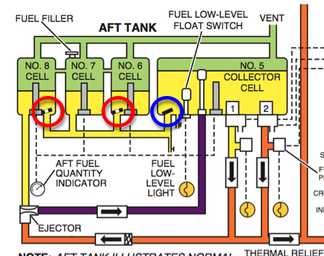
I am studying the Twin Otter and have a two part question regarding the flapper valves. I have inserted a diagram below of the aft tank, as it is essentially the same as the forward tank.
First off, what is the difference between the flapper valves in Cells 8 and 6 compared to the one located in Cell 5. The diagram depicts the first ones as two black lines, and the last one as a solid line (shown by two red circles, and one blue circle respectively). Am I correct to assume that the valves in cells 8 and 6 have a smaller hole in the middle of the valve to allow fuel to transfer out of the cell at a slower rate than into the cell (ie. fuel would be drawn out at a slower rate in flight, but would be added quickly while being refueled)?
My second question is what is the purpose of these same valves on cells 8 and 6. I can understand why 7 does not have one, as that is the cell which is connected to the aft refueling filler. And I can understand why 5 needs a valve, as it is the collector cell. The only reason for that valve the valves in cell 8 and 6 that I can think of is so fuel does not quickly move from cell to cell during a non cruise attitude.
I hope that makes some sense..
Cheers!
(Ps. I posted this question on avcanada as well)


Joined: May 2003
Posts: 198
Likes: 1
From: france
twin otter aft fuel tank
hello phu, the short answer is : pitching moments, gravity & fuel sloshing. the fuel tanks of the twin otter are mounted in tandem in the fuselage & have pitching moments around the center of gravity when the aircraft is climbing/descending. by doing so the aft fuel tank is either rotated down & tilted aft or is rotated up & tilted forward. now gravity kicks in & wants to equilize the fuel levels. this has an adverse effect on the piching moments. the answer is : flapper valves, which have an equilizing effect. depending on the tilt, this effect is an all/ nothing affair for valve 5( collector tank) & an all/calibrated, restricted affair for valves 6 & 8, due to the hole in these valves.
greetings,
bm
greetings,
bm
Joined: Feb 2000
Posts: 664
Likes: 0
From: HON121�/14 NM
Phu,
I'm not certain that your assumption of a hole in the flapper valve in cells 2,3, 6 and 8 is correct as I can't really see a need for it.
The man who can certainly answer your question is the great V1 oops. There isn't much about many of the smallest details of a Twin Otter that he doesn't know, and he wrote the FSI manual, and was been charged by DHC with keeping the manual updated when the aeroplane went out of production. Indeed he taught me everything that I used to know about the DHC-6 so I will be asking for a refund as here is question that he didn't give me the information about!
You should be able to get him via personal message. If you do please post the answer as you have me very intrigued now! Have a great time flying the aeroplane: you will never forget it!
Joined: Feb 2005
Aviation Qualifications: ATPL
Posts: 533
Likes: 41
From: Canada / Switzerland
Originally Posted by Phu
...The only reason for that valve the valves in cell 8 and 6 that I can think of is so fuel does not quickly move from cell to cell during a non cruise attitude.
Your analysis is absolutely correct. The holes in the flapper valves in the cells which are not collector cells and not cells with refuelling provisions are there to allow an adequate quantity of fuel to flow into the lower manifold to support fuel transfer to the collector cell via the ejector during normal operations.
As you pointed out, having a flapper valve with a hole in it permits rapid entry of fuel into the cell during refuelling operations (the flapper valve lifts up to allow fuel to enter from the manifold), but prevents noticeable center of gravity shifts from taking place during the climb and descent phases of flight.
The holes in the flapper valves also permit fuel to transfer to the collector cell (and from there to the engines) by gravity alone in the event of a failure of the normal motive flow system. This could be caused (for example) by blockage of the ejector cell, or a loss of all electrical power.
I have posted a photo of the actual contents of a collector cell below. This assembly is incomplete, but at least it will give you an idea of what all the parts shown in the collector cell schematic look like. I will try and get a picture of one of the flapper valves with a hole in it and post it here later this week (I might need to go down to the factory to find one).
Michael
Collector Cell Components (assembly is incomplete)

Joined: Feb 2005
Aviation Qualifications: ATPL
Posts: 533
Likes: 41
From: Canada / Switzerland
Here's a picture of a flapper valve from either cell 6 or cell 8 (or, perhaps, cell 2 or 3) showing the hole in the flapper valve. This is an old photo of mine of a classroom training aid.
Michael
Flapper Valve with Hole

Michael
Flapper Valve with Hole
Joined: May 2003
Posts: 198
Likes: 1
From: france
twin otter aft fuel tank
hello firestorm,
good remark about the "holes" of phu & his flapper valves. but i thinks the "holes" makes sense as it ensures a fuel feed to the collector tank(cell 5) from the other cells. assume a straigt & level flight, then all flapper valves are closed. analysing the diagramm of this aft fuel tank, i suppose the collector cell 5, feeds the engines through 2 boosterpumps & associated checkvalves. the boosterpumps, by means of the ejector draw fuel from cell 6 +7+8 into the collector cell 5.
i flew the twin otter in another life(1985) & i agree it's a fascinating experience.
v1 ooops is the best & confirms all above.
kregards,
bm.
Joined: Feb 2005
Aviation Qualifications: ATPL
Posts: 533
Likes: 41
From: Canada / Switzerland
Here is a picture showing the actual mechanicals at the bottom of cell number 8 - the small line delivering motive flow fuel (shown in orange in the schematic that Phu posted), the ejector assembly (which is actually mounted to the base of the plate in cell 8), and the larger pipe delivering the motive flow fuel and induced flow fuel (shown in purple in the schematic that Phu posted).
For clarity, the schematic shows the ejector as a stand-alone part a few inches below the fuel cell, but in actual practice, it is attached to the bottom of the fuel cell.
Actual Mechanical Components Corresponding to Phu's Schematic

For clarity, the schematic shows the ejector as a stand-alone part a few inches below the fuel cell, but in actual practice, it is attached to the bottom of the fuel cell.
Actual Mechanical Components Corresponding to Phu's Schematic

Joined: Sep 2024
Posts: 2
Likes: 0
From: Las Vegas, Nv
Jetguy23
This platform is a bit confusing as I finally made my way in via Facebook�. To add, I�ve been a Learjet mechanic (A&P) for a couple hundred years (year many hours in the (H hole) rail compartment R&R inverters�. The specific reason for this post is to re-assure people in my time Ive seen hundreds of damaged chafed cable but none so bad that it came close to complete failure. Those cables are rated at more that double maybe triple the estimated tensile strength it would take you hours to get through such a cable with a hack saw 🙏. Good day to you all and rest assured your always safe in the sky 🤙 cheers.
