


CPL Performance

Thread Starter
Join Date: Apr 2008
Location: Australia
Posts: 37
Likes: 0
Received 0 Likes
on
0 Posts
CPL Performance
This may be a stupid question but my instructor was unable to give me a straight or correct answer!!!!
CPL performance, I am studying bob tait for my exam next week and I cant seem to understand why he sometimes uses his flow charts for one question and similar or even the same types of questions he gets the weight and moment, plots it on the chart adds a convenient weight say 100 kg. .... Plots the new weight and moment draws a line between the old moment and new moment and where the line intersects the envelope that is the weight that can be added!!!!
Bob seems to use this method for weight to be added Eg......fuel, baggage or weight to be used as ballast but he also uses his flow charts as well!!!!
He seems to use both methods on similar questions but I have tried both methods and only one method seems to works for anyone questions.
Can Any Performance experts out there shed any light on my confusion???

Join Date: Jun 2006
Location: YMEN
Age: 37
Posts: 4
Likes: 0
Received 0 Likes
on
0 Posts
I believe that the 'graphical' method to determine the weight that can be added, can only be used when the CoG position moves in a non-linear manner. So basically if you have a forward CoG problem with the echo, you need to use the graphical method. If you really become stuck, the beauty about the CASA exam is that you can check all 4 multiple choice answers to see which one is in ballance - and then you have your answer.
Cheers
Cheers
Join Date: Mar 2008
Location: Up north
Posts: 40
Likes: 0
Received 0 Likes
on
0 Posts
You need to plot it when you need to add weight because the CG is outside the forward limit. Use the current weight and moment for one point, then find the weight and moment once you have added the 100kg or whatever further aft and plot this. Once you have plotted both points, join the dots, and where it intersects the moment envelope is the weight to add.
Bob uses the flow chart for the for adding weight (or shifting weight) when the CG is outside the aft limit. I never really understood the flow chart, so I just added the weights and moments step by step, then used the formula to work out weight to add/shift. It's a bit hard to explain it any better than this in writing.
Once you can do these questions in the review section at the back of the book, you'll be in a good position to do the exam.
echo question
If you have a rear problem in the echo aircraft always use the formula method.
If you have a forward problem where you are asked to shift weight always use the formula. The reason is because by shifting weight you are not changing the overall weight of the aircraft. Therefore the forward cg limit remains constant and therefore it can be used in the formula.
if you have a forward problem where you are asked to add or remove weight then the overall weight of the aircraft will change. this will change the forward cg limit. We dont know how much to add or remove, so if we dont know the weight, we dont know the forward cg limit. Tackle this problem graphically.
good luck with the exam. if you do drop the exam send me a pm. if you are in melbourne happy to sit down and go through it for the cost of a beer. cheers.
Thread Starter
Join Date: Apr 2008
Location: Australia
Posts: 37
Likes: 0
Received 0 Likes
on
0 Posts
Thanks guys, your posts have definitely shed some light on my dramas. I think I am starting to understand this evil performance.
Glenb,
Thanks mate I will let you know how I go. It is my last exam and my flight test is booked for next month so I really want to get through it first time.
Anyone give any tips on the best way to attack the exam??
Is there a good mix of Echo,Bravo,charlie,PNR's,EPT's fuel calculations ect in the exam?? or is it just manly Echo??
Moderator
Some of the considerations (and being a tad out of touch with the exams these days, I am trying to fill in some gaps here) are -
(a) if you are moving items around to change a CG, then the envelope limits will be constant and the traditional formula is the easy way to find the answer
(b) if you are adding/removing ballast and the target CG is known (generally this will mean the limits are fixed) the traditional formula is the easy way to go (but there is no reason why you can't run the answer graphically .. with the caveat that accuracy may suffer depending on the graph used ..).
(c) if the limits are changing (typically the upper forward limit and, sometimes, the aft upper limit) then you are faced with simultaneous equations complicated by the need to account for second order moment equations in the slopey limit bits and perhaps the load line. This is a bit silly for pilot folk, so the way to approach this is to plot the incremental ballast moment on a moment by weight diagram of the envelope and read off the answer required. CAVEATS -
(i) on the moment (or IU) chart, the slopey CG bits are NOT straight lines, although they may be approximated as such on many charts
(ii) while most light aircraft load items have a linear moment equation, some don't .. this is seen often in the fuel load. In these latter cases, the answer will have an error, of some amount, if one approximates the non-linear line by a straight line (linearising) .. this is precisely what you are doing by plotting an incremental weight co-ordinate (weight, moment) and drawing a straight line between the start and finish points when the real line is a bit on the wavy or segmented side.
If you can post a bit more information, I can give you the appropriate engineering answers to specific questions.
Some of the earlier comments from others are a bit wide of the mark so I'll keep an eye on this thread ... as weight control, for my sins, is one of my bread and butter activities ...
Thread Starter
Join Date: Apr 2008
Location: Australia
Posts: 37
Likes: 0
Received 0 Likes
on
0 Posts
Sample Echo Questions
These questions below are the types of questions i seem to use the wrong method on............
Echo A/C , Full man tanks and AUX tanks empty.
Gross weight= 2500kg
Total Moment index= 682 index units
The maxiuim fuel that may be loaded into the AUX tanks is...
A.141 lts
B.162 lts
C.204 lts
D.247 lts
Echo A/C
Gross weight= 2300kg
C of G postion = IU 548.5
Which answer best describes the min ballast that must be added to balance the aircarft.
A.5kg
B.14kg
C.20kg
D.26kg
Echo A/C
Gross weight= 2725
C of G postion = IU 678
What is the MIN weight that must be transfered to balance the A/C.
A.7kg
B.11kg
C.15kg
D.22kg
Moderator
You'd need to give us a bit of info re the sample aircraft to permit a quantitative answer. Is the manual on the CASA website for download ? or can you post a link to some scanned images of the pages ? or email them ?
echo question
short notice but i am helping a couple of fellas with this at mb airport friday morning between 9 and 12. call me 0418772013 if you want to join.
Thread Starter
Join Date: Apr 2008
Location: Australia
Posts: 37
Likes: 0
Received 0 Likes
on
0 Posts
Glenb,
Thanks for the invite mate, greatly appreciated... but I am based in Sydney. I wish my CFI was this helpful, you must be one of the few flying schools left that still deliver quality not quantity.
I will battle on with my trusty bob tait book and see what happens. If I flunk the exam at least it wont be from lack of effort I have put in several hours of study.
The problem with our instructors is that they are all still wet behind the ears (extremely young) and are just interested in clocking up there hours and aren�t very helpful when it comes to theory.
Thanks again.
Gearup2
Last edited by Gearup2; 25th Apr 2008 at 01:28.
I realise there are many instructors out there who do not want to be instructors, but there are also many instructors out there who do, many who do a superb job, and these are the ones you need to find.
PS, you'll need a lot more than "several hours study" to pass Performance. Good luck, you'll get there! Stay postive
Join Date: Mar 2008
Location: Sydney
Posts: 116
Likes: 0
Received 0 Likes
on
0 Posts
Lasiorhinus
I am sure "gearup2" has put in more than several hours of study and attended several theory classes. He is genuinely asking for help and advise!!! I have a pretty good idea what school he is with and theory isn�t a high prority on their list.
The problem is there are too many students for the amount of instructors!! If gearup2 hasn�t changed school by now he is probably locked into a diploma course. Just a guess!!!! No one stays if they aren�t getting what they paid for....
Good luck with the exam mate you seem to be working hard at it, I am sure it will all fall into place.
Join Date: Jul 2005
Location: short final
Posts: 20
Likes: 0
Received 0 Likes
on
0 Posts
Gearup2
I think I see where you have gone wrong.
If you're trying to shift weight with a C of G forward of the limit then you use flow chat also using the formula (Present Weight - 2360) x 0.27 + 2400 to find the forward C of G limit. You must use this method as you know the all up weight at T/O.
When you are adding or subtracting weight with the C of G forward of the limit you must use the graph method. You must use this method when you're still trying to determine overall T/O weight.
I hope this points you in the right direction, best of luck with your exam.
Moderator
The original poster has emailed me the current Echo docs etc. I'll put together some background explanation etc which might make it easier for you to see why you are doing what you are doing to come up with the answers. Main thing with weight control work is good housekeeping otherwise it is very easy to go off at a tangent ... unless you get involved with the more complex trimsheets, it doesn't get any more complicated than step a, step b, step c.
I'll potter about with this post progressively to add commentary on the files provided which include what appears to be a schedule of formulae and how-to-do-it flowcharts ...
Any specific questions .. please post and I'll endeavour to give you a sensible answer. Also, should you see a typo, please advise and I'll correct it.
A. Moment Index
The file gives the following
moment index = (weight x arm)/index unit
index unit = 100, 1000, etc
I have some reservation with terminology aspects of this.
Weight and balance calculations necessarily involve simple arithmetic moment calculations or an easy housekeeping record of clockwise and anticlockwise moment sums.
Moment is just the product (arithmetic jargon for multiplication) of a distance (what we usually call the "loading arm" or, more simply, the "arm") and a weight (strictly mass but that's not too important a distinction for pilot work).
The concept called "centre of gravity" is the point in a loading arrangement where there is no residual moment left over trying to rotate the system about the CG position (imagine a fulcrum position located at the CG position) ie we refer to the CG as being the point where the sum (jargon for the total addition) of the moments (with the calculations done for the CG position) is zero. Strictly this will be true for any point (datum) for which the calculations are done .. as seen later when we consider the significance of the datum position.
[I'll belabour the moment concept for a bit as, if this is not understood, then understanding the whole lot falls down in a heap.]
The moment sum idea results in the usual CG calculation table with which pilots have to contend. Initially, I'll draw this in the usual pilot way .. which is not strictly correct ..
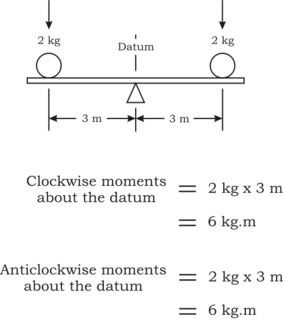
Clearly this system is "balanced" (like a see-saw in the local park) and there is nothing there tending to rotate the support beam. If we calculate a simple moment equation as shown in the sketch, we can see that the total (the "sum") of the moments tending to rotate the beam clockwise is the same in magnitude as the total of the moments tending to rotate the beam anticlockwise.
Note that the moment is the product of a length and a weight and MUST have units of length x weight. In this calculation the units are metres and kilograms, generally written as kg.m
Clearly, you can generate more complicated systems to emphasise the point.
Conventionally, we set clockwise moments to be positive (plus values) and anticlockwise moments to be negative (minus values). This results in
(a) arms to the left of the datum being negative
(b) arms to the right of the datum being positive
(c) loads added being positive
(d) loads removed being negative
This sign (plus and minus) convention allows us to run the calculations arithmetically rather than keep tabs on clockwise and anticlockwise moments.
If we do that in this first simple case we get
clockwise moments = (+2) kg x (+3) m = (+6) kg.m = 6 kg.m
anticlockwise moments = (+2) kg x (-3) m = (-6) kg.m
and, if we add the two together (sum the calculations) we get
total moment = 6 kg.m - 6 kg.m = 0 kg.m
Note that, if you don't like pluses and minuses, you can run all the calculations by keeping track of clockwise and anticlockwise moments.
We say that the present datum position is the CG of the system because there is no tendency for any rotation .. ie the clockwise and anticlockwise moments balance out .. or, the sum of the moments is zero.
I suggested before that the picture was not quite correct. If we were to pick up the whole thing and put it onto some bathroom scales, the scales would indicate 4 kg (assuming that the weight of the plank and fulcrum were negligible). This 4 kg load doesn't affect the moments in this calculation (as it is in line with the datum and has a zero arm) but will for any other datum.
The next consideration is whether the datum location is significant ? Answer = no. In particular, the datum has no greater significance than being somewhere convenient to hang the end of one's tape measure on .. the ONLY important thing is that, once chosen, you MUST do all your sums with arms measured from the same datum .. otherwise it all turns into a wonderful mess ...
Look at the case where we take the datum for calculation to be moved to the left, say .. Has this changed the see-saw balance situation ? Of course it hasn't, but let's have a look at the sums to see what happens to the numbers. (This graphic insists on posting too big .. eventually I'll work out how to fix that).
If we use the arithmetic approach, the clockwise total moment is 24 kg.m and the anticlockwise moment - 24 kg.m and the total moment remains zero. You can play with moving the datum here and there and the situation stays the same .. the numbers change but the significance (and the balance consideration) doesn't.
Index Units
If we venture into the real world, especially with large aeroplanes, the moments can become VERY big numbers, especially if arms are measured in millimetres (mm). Considering the accuracy required and manipulation convenience, we really don't want to play with the sort of big numbers which can arise .. so we need a technique to simplify things .. and we end up with index units, by convention.
Index Unit (IU) is defined (ie we say that this is what an IU is)
IU = moment/a convenient constant moment
eg = 134,534,058 kg.mm / 1,000,000 kg.mm
= 134.534058
which we would round off to something like 134.53, say.
Note that the quantity we divide by is a "convenient constant moment". This means it is
(a) a moment (ie it has moment units .. kg.m, kg.mm, ton.yards .. whatever)
(b) a constant and is used for ALL calculations in a given problem or weight control situation
(c) chosen for convenience .. ie there is nothing intrinsically important about the number .. you might use 10, 10000, 12345, whatever .. the ONLY important thing is that, once chosen, you stick with the same convenient constant
and that the resulting IU has no dimensions (units) .. ie the IU is a plain, old, ordinary number.
Turning to the how-to-do-it document, the terminology chosen is very confusing in that it is not compatible with the normal conventions. I suggest that you think more conventionally and replace it with
IU = weight x arm/constant moment
where "constant moment" is any convenient value, usually powers of 10 for arithmetic simplicity.
The only other thing to keep in mind is whether you are working in moments or IU as the equations needed to work things out are a little different to take into account the difference between moment and IU as defined in the equation above. So long as you remember that the sums must involve moments and, if you are working in IU you have to convert to/from moment for the sums, you won't go too far wrong.
B. Calculating the CG
Using the example above, the CG calculation falls out pretty simply. We are trying to figure where to put a "balance point" so that the moments all cancel out. A very simple way to do this is to consider all the aircraft loads first and then work out a balancing load. The IU column is not necessary in this case but makes the numbers a bit easier to work with generally when we are looking at big numbers .. For this case, let's use an IU constant of, say, 10 to see what is going on.
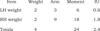
Notice that
(a) moment = weight * arm
(b) IU = moment / constant
In practice we would choose either to include the moment or the IU column rather than both.
Notice that we have
(a) added the weights to get a total weight .. this gives us the weight on the scales as before
(b) added the moments (or IU) to give a total moment (or IU)
Please don't do anything with the "Arm" column and note very clearly that moments are NOT the same as IU .. related, yes, but not the same thing at all.
Now, to figure the CG, we recall that we need to achieve a zero total moment. That is, we need to do a sum to work out what CG value would make the following equation correct
total weight x CG = total moment
rearranging we might just as easily say we need to figure out
CG = total moment / total weight.
Plugging in the numbers gives
CG = 24/4 = 6
which we know to be the correct answer from the earlier calculations.
If we had chosen to do the sums in IU, rather than moments, we just need to make sure that we incorporate the IU to moment conversions in the CG sum.
CG = total moment / total weight
= (total IU *constant) / total weight
= (2.4 * 10) / 6
= 24 /6
= 6
which is what we expected to see.
... and, conceptually, that's about as hard as it gets .. the problem is housekeeping to make sure that we don't lose numbers along the way.
Conventionally, we "park" the CG answer in the table between the total weight and total moment values but it is very important to remember that the CG value is just parked there and doesn't follow the calculation pattern of the other line items in the table.
C. Mean Aerodynamic Chord (MAC)
Why do we get involved with MAC when, for a pilot (other than test pilots), it is absolutely of no interest to us ?
Solely because, conventionally, the AFM/POH loading information is prepared by the aerodynamicists in the design team (good chaps like djpil). The aerodynamicist is very interested in MAC for a host of non-W&B reasons but, being busy and not having time to rework the sums back to station values, generally presents all the limitations in MAC terms, rather than arms. It doesn't make any difference, other than for making the pilot's job a tad more involved arithmetically.
Relationship between Station Arms and Percentage MAC
For weight and balance, we are interested only in being able to convert percent (or fraction) MAC to/from fuselage station (arm). The two are only different ways of writing the same thing .. how far is something from the loading datum .. no more, no less.
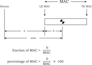
This is all we need to know about %MAC.
Converting from Fuselage Station (arm) to % MAC
First we need to work out the distance back to the station from the MAC leading edge. Clearly this is
b = arm - a
where a is the distance from the datum to the LE MAC. Then we plug the value into the percentage MAC equation
%MAC = b/MAC * 100
= (arm - distance to LE MAC)/length MAC * 100
Converting from % MAC to Fuselage Station (arm)
Now, we can get b from the MAC equation
b = %MAC * MAC/100
so
arm = a + b
= distance to LE MAC + %MAC * MAC/100
It is important to be clear that %MAC is just another (inconvenient for pilots) way of saying loading arm.
For the Echo POH, the equations simplify to
arm = 2190 + 19 * %MAC
%MAC = (arm - 2190)/19
The formula schedule provided contains the following for MAC
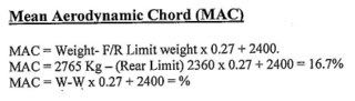
I suggest that you don't try to use this .. it is nonsense as it is presented .. ie plain wrong. However, we can make some sense of it with a bit of tweaking and changing this and that.
The expressions above appear to be an attempt to describe the equation of the upper forward CG envelope limit (ie the slopey bit). If we reorder the terms and correct the odd error in the first expression we end up with
upper forward limit = 2400 + 0.2711864 * (GW - 2360)
where GW is gross weight within the range 2360 - 2950 kg and 0.2711864 is the slope (gradient) of the limit in mm/kg. What this is doing is saying "add to 2400 mm the prorated arm increment as weight increases above 2360 kg to get the forward limit at the higher weight".
A slightly simpler equation which does the same task is
upper forward limit = 1760 + 0.2711864 * GW
What it doesn't do is calculate the %MAC which is what it appears to be trying to do. If we look at the second expression in the formula schedule, we can see that for 2765 kg, the forward limit is 2510 mm and an arm of 2510 mm works out to be the same as 16.8 %MAC.
D. Floor Loading
The how-to-do-it document is a bit lax in that it doesn't keep track of the units.
Main point to keep in mind is that floor loading limits are similar to pressure or stress limits with units of force/area. If the actual value is less than the limitation (for the Echo 450 kg/m2), then you are fine (for that limitation, anyway).
Looking at the example given, with a 20kg box of base dimensions 200mm x 200mm (remember to convert mm to metres)
load = 20 kg
and
area = 200/1000 * 200/1000
= 0.2 * 0.2
= 0.04 m2
resulting in a floor loading intensity
FL = force / area
= 20 kg/0.04 m2
= 500 kg/m2
which is too high so you will need some shoring to spread the load over a greater floor area.
(Continued at post 19 to avoid the attention of the post length limit police ...)
I'll potter about with this post progressively to add commentary on the files provided which include what appears to be a schedule of formulae and how-to-do-it flowcharts ...
Any specific questions .. please post and I'll endeavour to give you a sensible answer. Also, should you see a typo, please advise and I'll correct it.
A. Moment Index
The file gives the following
moment index = (weight x arm)/index unit
index unit = 100, 1000, etc
I have some reservation with terminology aspects of this.
Weight and balance calculations necessarily involve simple arithmetic moment calculations or an easy housekeeping record of clockwise and anticlockwise moment sums.
Moment is just the product (arithmetic jargon for multiplication) of a distance (what we usually call the "loading arm" or, more simply, the "arm") and a weight (strictly mass but that's not too important a distinction for pilot work).
The concept called "centre of gravity" is the point in a loading arrangement where there is no residual moment left over trying to rotate the system about the CG position (imagine a fulcrum position located at the CG position) ie we refer to the CG as being the point where the sum (jargon for the total addition) of the moments (with the calculations done for the CG position) is zero. Strictly this will be true for any point (datum) for which the calculations are done .. as seen later when we consider the significance of the datum position.
[I'll belabour the moment concept for a bit as, if this is not understood, then understanding the whole lot falls down in a heap.]
The moment sum idea results in the usual CG calculation table with which pilots have to contend. Initially, I'll draw this in the usual pilot way .. which is not strictly correct ..
Clearly this system is "balanced" (like a see-saw in the local park) and there is nothing there tending to rotate the support beam. If we calculate a simple moment equation as shown in the sketch, we can see that the total (the "sum") of the moments tending to rotate the beam clockwise is the same in magnitude as the total of the moments tending to rotate the beam anticlockwise.
Note that the moment is the product of a length and a weight and MUST have units of length x weight. In this calculation the units are metres and kilograms, generally written as kg.m
Clearly, you can generate more complicated systems to emphasise the point.
Conventionally, we set clockwise moments to be positive (plus values) and anticlockwise moments to be negative (minus values). This results in
(a) arms to the left of the datum being negative
(b) arms to the right of the datum being positive
(c) loads added being positive
(d) loads removed being negative
This sign (plus and minus) convention allows us to run the calculations arithmetically rather than keep tabs on clockwise and anticlockwise moments.
If we do that in this first simple case we get
clockwise moments = (+2) kg x (+3) m = (+6) kg.m = 6 kg.m
anticlockwise moments = (+2) kg x (-3) m = (-6) kg.m
and, if we add the two together (sum the calculations) we get
total moment = 6 kg.m - 6 kg.m = 0 kg.m
Note that, if you don't like pluses and minuses, you can run all the calculations by keeping track of clockwise and anticlockwise moments.
We say that the present datum position is the CG of the system because there is no tendency for any rotation .. ie the clockwise and anticlockwise moments balance out .. or, the sum of the moments is zero.
I suggested before that the picture was not quite correct. If we were to pick up the whole thing and put it onto some bathroom scales, the scales would indicate 4 kg (assuming that the weight of the plank and fulcrum were negligible). This 4 kg load doesn't affect the moments in this calculation (as it is in line with the datum and has a zero arm) but will for any other datum.
The next consideration is whether the datum location is significant ? Answer = no. In particular, the datum has no greater significance than being somewhere convenient to hang the end of one's tape measure on .. the ONLY important thing is that, once chosen, you MUST do all your sums with arms measured from the same datum .. otherwise it all turns into a wonderful mess ...
Look at the case where we take the datum for calculation to be moved to the left, say .. Has this changed the see-saw balance situation ? Of course it hasn't, but let's have a look at the sums to see what happens to the numbers. (This graphic insists on posting too big .. eventually I'll work out how to fix that).
If we use the arithmetic approach, the clockwise total moment is 24 kg.m and the anticlockwise moment - 24 kg.m and the total moment remains zero. You can play with moving the datum here and there and the situation stays the same .. the numbers change but the significance (and the balance consideration) doesn't.
Index Units
If we venture into the real world, especially with large aeroplanes, the moments can become VERY big numbers, especially if arms are measured in millimetres (mm). Considering the accuracy required and manipulation convenience, we really don't want to play with the sort of big numbers which can arise .. so we need a technique to simplify things .. and we end up with index units, by convention.
Index Unit (IU) is defined (ie we say that this is what an IU is)
IU = moment/a convenient constant moment
eg = 134,534,058 kg.mm / 1,000,000 kg.mm
= 134.534058
which we would round off to something like 134.53, say.
Note that the quantity we divide by is a "convenient constant moment". This means it is
(a) a moment (ie it has moment units .. kg.m, kg.mm, ton.yards .. whatever)
(b) a constant and is used for ALL calculations in a given problem or weight control situation
(c) chosen for convenience .. ie there is nothing intrinsically important about the number .. you might use 10, 10000, 12345, whatever .. the ONLY important thing is that, once chosen, you stick with the same convenient constant
and that the resulting IU has no dimensions (units) .. ie the IU is a plain, old, ordinary number.
Turning to the how-to-do-it document, the terminology chosen is very confusing in that it is not compatible with the normal conventions. I suggest that you think more conventionally and replace it with
IU = weight x arm/constant moment
where "constant moment" is any convenient value, usually powers of 10 for arithmetic simplicity.
The only other thing to keep in mind is whether you are working in moments or IU as the equations needed to work things out are a little different to take into account the difference between moment and IU as defined in the equation above. So long as you remember that the sums must involve moments and, if you are working in IU you have to convert to/from moment for the sums, you won't go too far wrong.
B. Calculating the CG
Using the example above, the CG calculation falls out pretty simply. We are trying to figure where to put a "balance point" so that the moments all cancel out. A very simple way to do this is to consider all the aircraft loads first and then work out a balancing load. The IU column is not necessary in this case but makes the numbers a bit easier to work with generally when we are looking at big numbers .. For this case, let's use an IU constant of, say, 10 to see what is going on.
Notice that
(a) moment = weight * arm
(b) IU = moment / constant
In practice we would choose either to include the moment or the IU column rather than both.
Notice that we have
(a) added the weights to get a total weight .. this gives us the weight on the scales as before
(b) added the moments (or IU) to give a total moment (or IU)
Please don't do anything with the "Arm" column and note very clearly that moments are NOT the same as IU .. related, yes, but not the same thing at all.
Now, to figure the CG, we recall that we need to achieve a zero total moment. That is, we need to do a sum to work out what CG value would make the following equation correct
total weight x CG = total moment
rearranging we might just as easily say we need to figure out
CG = total moment / total weight.
Plugging in the numbers gives
CG = 24/4 = 6
which we know to be the correct answer from the earlier calculations.
If we had chosen to do the sums in IU, rather than moments, we just need to make sure that we incorporate the IU to moment conversions in the CG sum.
CG = total moment / total weight
= (total IU *constant) / total weight
= (2.4 * 10) / 6
= 24 /6
= 6
which is what we expected to see.
... and, conceptually, that's about as hard as it gets .. the problem is housekeeping to make sure that we don't lose numbers along the way.
Conventionally, we "park" the CG answer in the table between the total weight and total moment values but it is very important to remember that the CG value is just parked there and doesn't follow the calculation pattern of the other line items in the table.
C. Mean Aerodynamic Chord (MAC)
Why do we get involved with MAC when, for a pilot (other than test pilots), it is absolutely of no interest to us ?
Solely because, conventionally, the AFM/POH loading information is prepared by the aerodynamicists in the design team (good chaps like djpil). The aerodynamicist is very interested in MAC for a host of non-W&B reasons but, being busy and not having time to rework the sums back to station values, generally presents all the limitations in MAC terms, rather than arms. It doesn't make any difference, other than for making the pilot's job a tad more involved arithmetically.
Relationship between Station Arms and Percentage MAC
For weight and balance, we are interested only in being able to convert percent (or fraction) MAC to/from fuselage station (arm). The two are only different ways of writing the same thing .. how far is something from the loading datum .. no more, no less.
This is all we need to know about %MAC.
Converting from Fuselage Station (arm) to % MAC
First we need to work out the distance back to the station from the MAC leading edge. Clearly this is
b = arm - a
where a is the distance from the datum to the LE MAC. Then we plug the value into the percentage MAC equation
%MAC = b/MAC * 100
= (arm - distance to LE MAC)/length MAC * 100
Converting from % MAC to Fuselage Station (arm)
Now, we can get b from the MAC equation
b = %MAC * MAC/100
so
arm = a + b
= distance to LE MAC + %MAC * MAC/100
It is important to be clear that %MAC is just another (inconvenient for pilots) way of saying loading arm.
For the Echo POH, the equations simplify to
arm = 2190 + 19 * %MAC
%MAC = (arm - 2190)/19
The formula schedule provided contains the following for MAC
I suggest that you don't try to use this .. it is nonsense as it is presented .. ie plain wrong. However, we can make some sense of it with a bit of tweaking and changing this and that.
The expressions above appear to be an attempt to describe the equation of the upper forward CG envelope limit (ie the slopey bit). If we reorder the terms and correct the odd error in the first expression we end up with
upper forward limit = 2400 + 0.2711864 * (GW - 2360)
where GW is gross weight within the range 2360 - 2950 kg and 0.2711864 is the slope (gradient) of the limit in mm/kg. What this is doing is saying "add to 2400 mm the prorated arm increment as weight increases above 2360 kg to get the forward limit at the higher weight".
A slightly simpler equation which does the same task is
upper forward limit = 1760 + 0.2711864 * GW
What it doesn't do is calculate the %MAC which is what it appears to be trying to do. If we look at the second expression in the formula schedule, we can see that for 2765 kg, the forward limit is 2510 mm and an arm of 2510 mm works out to be the same as 16.8 %MAC.
D. Floor Loading
The how-to-do-it document is a bit lax in that it doesn't keep track of the units.
Main point to keep in mind is that floor loading limits are similar to pressure or stress limits with units of force/area. If the actual value is less than the limitation (for the Echo 450 kg/m2), then you are fine (for that limitation, anyway).
Looking at the example given, with a 20kg box of base dimensions 200mm x 200mm (remember to convert mm to metres)
load = 20 kg
and
area = 200/1000 * 200/1000
= 0.2 * 0.2
= 0.04 m2
resulting in a floor loading intensity
FL = force / area
= 20 kg/0.04 m2
= 500 kg/m2
which is too high so you will need some shoring to spread the load over a greater floor area.
(Continued at post 19 to avoid the attention of the post length limit police ...)
Thread Starter
Join Date: Apr 2008
Location: Australia
Posts: 37
Likes: 0
Received 0 Likes
on
0 Posts
john_tullamarine,
Mate thanks a lot for the info, it has obviously taken a bit of your time to work through the in and outs of ECHO loading. I definitely understand what you are saying and I will try it out on a few practice questions shortly.
The exam is tomorrow!!! So I will try it out on a few questions and use the method that seems to work accurately and quickly for me.
You�re a true PPRUNER and a performance expert in my opinion.
If you are ever in Sydney would love to buy you a few beers to say thank you!!
I will report back with my KDR tomorrow!!!!!!!!
Last edited by Gearup2; 28th Apr 2008 at 12:22. Reason: Spelling
Moderator
Dave, the FAA book is not a bad reference but not aligned well enough to the CPL type training needs. The old DCA pub (which came out when you and I were still but wee little lads) still is probably the best around for the trainee pilot .. never did find out who penned that one .. would have to be in Ron's era, I guess.
Thread Starter
Join Date: Apr 2008
Location: Australia
Posts: 37
Likes: 0
Received 0 Likes
on
0 Posts
JT,
I ended up being able to use the method described above in the exam. I didn�t really understand the concept all that well to start with, but I was able to grab one of our older ground theory instructors in the morning before the exam (possibly from your era). He was able to work through exactly what you have described above with very similar diagrams. Surprised they didn�t teach this method first off in class which would have saved a bit of stressing!
Anyway just got through the exam 74% in the end, my KDR didn�t show any weight and balance errors �.. got them all right!!!! (I used the above method not the flow charts) It was the take off and landing charts (PPL stuff I know) where my errors were made.
It is my lowest mark out of the seven exams but just glad to get through first go. I have JT the performance guru to thank for that!!!!!
Lesson learned from this subject ......seek help sooner if one particular method isn�t working for me!!!!
John, cant thank you enough for your help!!!! A carton of cold crowniees awaits you in Sydney!!!!!!
Moderator
Well done, that man. Crownies promise noted and logged in the diary for a convivial collection.
With many of the exam question stuff, there are multiple ways to get to the answer. So long as the method is sensible and the working error free, all is well .. and, certainly, if Method A makes no sense, give it away and use Method B.
(Continued from post 14)
(Misplaced this thread along the way, so I'll continue with the tale now. Have misplaced the training notes .. not that that matters as I'm sure that they will have been updated from time to time along the way ..)
E. Shifting Weight to Alter the CG (Reloading the Aircraft)
First point .. ALWAYS sketch a picture to suss out the arrangement.
This situation arises, typically, when a calculated intended load puts the CG outside limits (or outside a desired location) and we need to rearrange the load to achieve the required/desired CG location.
Recall that the CG was calculated by finding a suitable balance location which gave a zero total moment. It follows that, if the CG, now, is "wrong", then the total moment is "wrong" so we need to rework the moment sums to suit and find a sum which meets the need to have zero total moment about the new CG position.
Let's say that the new CG required is located a distance from the old CG which we will call δCG .. this is just the distance between the two CG positions. For convenience, let's put the new CG to the right of the old CG (we can call it the datum position for the next calculations to make things easier to follow) and have, say, a baggage compartment in the nose (at distance - s1 from the datum) from which we can take some weight and another in the back (at distance s2 from the datum) into which it might be put ..
Calculating moments about the new CG position we would get something like ..
total moment = -w x -s1 + w x s2 - GW x δCG (the last term because the old CG is now -δCG from where we want to have the new CG) ..
but, for the new datum position to be the CG, the total moment must be zero, by definition .. a bit of rearranging and we get
w x (s1 + s2) = GW x δCG
and a tad more rearranging ..
w/GW = δCG/(s1 + s2)
This we could describe, generically, as
weight to be moved ____ distance between the two CG positions
---------------------- = -------------------------------------------
gross weight___________ distance between the two load stations
(if you didn't follow the story with ease, don't worry .. the end generic equation is the thing to remember ..)
F. Adding/Removing Weight to Alter the CG (Ballasting)
First point .. ALWAYS sketch a picture to suss out the arrangement.
This is much the same as rearranging some load .. let's say we want to move the CG to the right and we have a suitable compartment in the tail for adding some weight to achieve the required CG change. We can set up a similar total moment expression with the datum at the new CG position ..
total moment = w x s - old GW x δCG (note that s is the distance from the new CG - the datum - to the ballast station location)
putting the total moment equal to zero to force the datum position to be the new CG gives us ..
w/old GW = δCG/s
which, generically, can be described as
ballast weight ________ distance between the two CG positions
--------------- = ---------------------------------------------------
old GW __________distance from the new CG to the ballast station
Again, don't sweat the sums too much .. the end generic relationship is what you are after.
The same sort of generic expression can be used for removing weight from a station.
G. Using Fuel as Ballast
As a general principle, use of fuel for ballast in light aircraft is not a good practice .. small quantities, often poor gauging capabilities and, then, if you have an operational need to go into that fuel in flight, you might find yourself out of control prior to having to demonstrate your Gimli gliding capabilities.
A bit different with heavy aircraft which, generally, have the advantage of being subject to a more rigorous management oversight regarding procedural protocols etc.
Having said that, you can use fuel in the balance calculations in the same manner as described earlier.
H. How about Graphical Approaches to Envelope CG Calculations ?
One typical problem sees the initial aircraft loaded a bit outside either the forward or aft CG envelope limit. Clearly, one needs to fix this prior to flight. The usual way is either to rearrange the existing load to suit or, alternatively, add ballast/offload payload.
If the problem is in the constant CG regions (lower weight forward and all the aft limit range), the previous simple approaches work fine. No reason why you can't do it graphically .. just doesn't make any sense and, generally, ends up less accurate ..
If, however, you are in the higher weight forward limit region where the CG moves aft with increasing weight, such an approach doesn't work with the moving target ballast technique. We can sort out this problem by one of two methods -
(a) this isn't the recommended approach but is noted for those who might have an interest - the CG limit line (on the W-IU limit chart) is a simple quadratic and, by figuring a particular ballast line equation (linear for the Echo .. but not always the case), the two can be solved simultaneously to find the required ballast weight. Although not a difficult exercise, per se, it's just too painful either for exams or real world flying .. so let's not go there.
(b) the pragmatic alternative to (a) is a graphical implementation of the simultaneous solution. Simply plot the incorrect loaded W-IU point (outside the envelope) and then a second ballasted load point (inside the envelope). On the W-IU chart, you can join these two points with a straight line - provided the ballast arm is constant - and read off the intersection with the CG limit to figure how much ballast weight is needed to fix the misload.
I. Miscellaneous Comments on the Echo POH Loading Data
(a) seat loads. Removing seats usually involves a slightly different arm to that used for the occupant. However, since the manual doesn't make the distinction, one uses the one common loading arm. The reference to 82kg max in the (removed) seat position refers to the normal seat structural design load to cover a 170lb/77kg occupant - ie, unless you have further information, the floor limit is presumed to be 77kg + seat weight for simplicity. For the same reason, seat loading is limited to 77kg unless a specific loading design permitting a higher load is implemented.
(b) load charts. The presentation is typical GAMA POH format and one which you will see in many light aircraft POH weight and balance sections. This has an unfortunate consequence of using the OEM FS datum in that the W-IU chart is rather dreadful due to the pronounced slope from lower left to upper right. The main problem arising is that the plotting accuracy in use is compromised.
Compare this chart with, say, the Alpha loading system. In the latter, the datum is a typical trimsheet trim datum (ie not the OEM FS datum) and, although there is not enough information to work out just what the trim datum is, we can observe that it either is, or is very close to, the fuel arm position. A quick look at the resulting envelope in the trimsheet shows a very much better layout for accurate plotting .. this is the main reason we use non-OEM trim datums for trimsheets. Indeed, the larger aircraft OEMs usually schedule the OEM loading systems using a similar trim datum philosophy. The quick way to tell if a chart uses a sensible datum is to observe if the envelope is "squarish" or boxy (such as for the Alpha) rather than very slopey and elongated (as for the Echo and Bravo).
Caveat - with ultra lengthy, complicated posts, there is always the chance of keystroke or similar errors unless the information is peer-reviewed. If you see, or even think you see, something a bit strange, please let me know so that I can check it out ..
