


New RAF Transport

Join Date: Apr 2008
Location: The Whyte House
Age: 95
Posts: 1,966
Likes: 0
Received 0 Likes
on
0 Posts
Front of the jig perhaps?
I seem to recall it was 245 inches back from the start of the jig, or whatever gubbins sat forward of the 'frame, during construction.

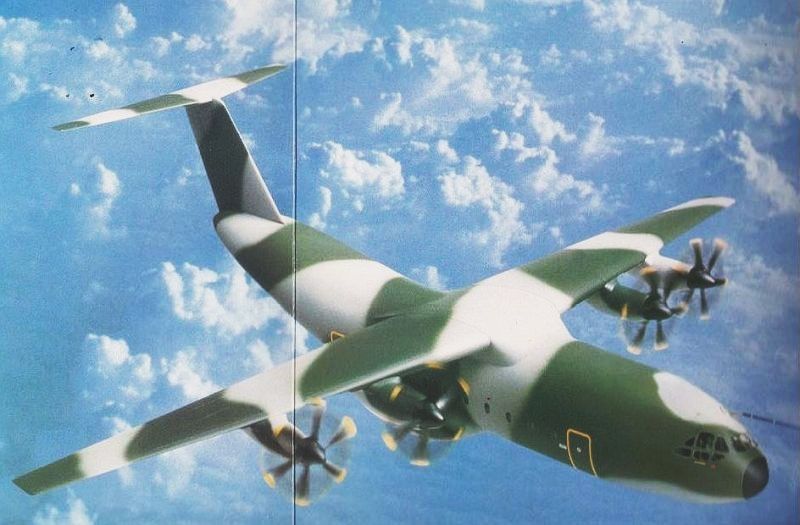
Earlier designs of the A400M (or rather 'FLA' as it was then known) had a significantly different fin and tailplane design:
When I sat in the mock-up at Farnborough around 20 years ago, one feature I considered to be excellent - the lower flight deck windows allowed excellent 'forward and down' observation. So I was rather surprised to note that these haven't made it into production.

When I sat in the mock-up at Farnborough around 20 years ago, one feature I considered to be excellent - the lower flight deck windows allowed excellent 'forward and down' observation. So I was rather surprised to note that these haven't made it into production.
Willard, I don't think you will get one.
I have had first hand experience of alloy airframe BDR during Corporate, Harrier and Victor, and I have often wondered about composite airframe BDR. Like yourself, I haven't been able to get an answer.
I have had first hand experience of alloy airframe BDR during Corporate, Harrier and Victor, and I have often wondered about composite airframe BDR. Like yourself, I haven't been able to get an answer.
Years ago the Science Museum in South Kensington, London, had an exhibit all about battle damage repair methods to be used on the composite AV-8B Harrier wing.
I can imagine Airbus and the MOD not wanting share information about the techniques they intend to use on the A400M, for both commercial and military reasons, but its a 'dead cert' that they know the sequence they will be using when the need arises.
I can imagine Airbus and the MOD not wanting share information about the techniques they intend to use on the A400M, for both commercial and military reasons, but its a 'dead cert' that they know the sequence they will be using when the need arises.
Had one flying over Peterborough the other week. Apparently Tom Cruise was strapped on the side, although it was at low level, I didn't see him.
Q. Looking at the head on flare shot, do engines 1 & 3 rotate in the opposite direction to 2 & 4?
Q. Looking at the head on flare shot, do engines 1 & 3 rotate in the opposite direction to 2 & 4?
TP400 rotation direction is 'down between engines'.
Hence viewed from the front, propellers of odd-numbered engines rotate in an anti-clockwise direction and even-numbered in a clockwise direction.
Hence viewed from the front, propellers of odd-numbered engines rotate in an anti-clockwise direction and even-numbered in a clockwise direction.
Join Date: Feb 2006
Location: Hanging off the end of a thread
Posts: 33,055
Received 2,927 Likes
on
1,250 Posts
Stn 0 aint nothing to to do with probe and from reading your posts you are a tornado man where was stn 0 on a gr1


Join Date: Mar 2005
Location: Holly Beach, Louisiana
Posts: 916
Likes: 0
Received 0 Likes
on
0 Posts
Hence viewed from the front, propellers of odd-numbered engines rotate in an anti-clockwise direction and even-numbered in a clockwise direction.
Thanks for the explanation Beags.
I must admit it looked mighty good flying around, made a strange noise though, prop like one moment then sounding like a jet the next. There again, it might have been Tom screaming!
I must admit it looked mighty good flying around, made a strange noise though, prop like one moment then sounding like a jet the next. There again, it might have been Tom screaming!
It may be purely co-incidental but the size of the A400M tailplane grew after Boscombe Down supplied Airbus with a trace of a Hercules HSP drop that showed a transient MAC of over 100% at the point the load left the ramp. 
Join Date: Jan 2003
Location: Leicestershire, England
Posts: 1,170
Likes: 0
Received 0 Likes
on
0 Posts
Seems there's still quite a bit of work to done be yet...
Airbus confident on A400M deliveries despite capability shortfall - 11/14/2014 - Flight Global
-RP
Airbus confident on A400M deliveries despite capability shortfall - 11/14/2014 - Flight Global
-RP


Atlas design - your comments
Most of the comments so far seemed as much based on ignorance as anything else.
The position of the horizontal stabiliser (HS)(or tail plane) is relatively easily explained. As it is an all flying tail plane ( as with most modern aircraft) it needs a motor to drive it. This motor is normally at the base of the fin but, because of the opening back end, the door goes into the space at the tail of the aircraft and there is insufficient structure to house the motor. It is, therefore necessary to move the HS up the fin. Once you have moved it up there are then aerodynamic reasons to go all the way just as in the C17.
Propeller rotation - again aerodynamics plays a role but also noise. The inboard rotation is as it is to reduce noise inside the cargo bay and induce a flow round the tail which helps the paratroops to not get swept underneath to wrap round those from the other side exit. The outboard rotation also has an aerodynamic effect especially for the engine failure case - with this arrangement there is, in effect, no critical engine for the engine out case other than an outboard being not as good as an inboard. The combined effect is also improved flow drag characteristics which helped reduce the size, and therefore the weight, of the of the fin and the HS which also helps with fuel consumption/range for a given fuel.
Both, as with all else in the design, were the result of long and detailed studies and wind tunnel testing. I hope this explanation helps.
Like with the introduction of the C130 way back, the looks of the aircraft bear little relevance to its capability in service. With the years spent in development and test, it's to be hoped that for once the RAF receive a credible result of their Operational Requirement. Someone has already stated that in its infancy Albert was no beauty, but many of us love the beast to this day. Good luck to this aircraft in service, it's crews and those who support it.
Smudge
Smudge
Join Date: Nov 2012
Location: UK East Anglia
Age: 66
Posts: 678
Likes: 0
Received 0 Likes
on
0 Posts
Xerc, Appears odd having to do airdrop and parachuting at altitude with the wheels down in an effort to control the vortices. prevent crossover and being dragged under. This was not picked up during all the FEA and CFD they did down in Toulouse and academia to my knowledge. I am guessing it was one of VX275s mates who came up with the solution.
Taken a long time in development but I do think it will be a great machine in a few years time.
On Frame Stations: Years back each metal hoop was given a number some started at the front and others in the middle with minus numbers forward +ve aft. Not sure if the mercans started using inches. FS 0 on the Chinook was in fresh air quite a way out front.
Can anyone tell me if the stn numbers on A400 are in metric. I seam to recall that the tie downs were on a 20" grid. I left all my data sheets behind when I left.
Join Date: Aug 2014
Location: New Braunfels, TX
Age: 70
Posts: 1,954
Likes: 0
Received 0 Likes
on
0 Posts
I like it's looks. Congrats to Airbus and the RAF.
I've got two questions:
1. Will the RAF call it an Atlas? Or is that just an Airbus name?
2. What were the drivers for the cargo floor dimensions, especially the width? The 13 ft width seems like an odd choice to me, but I'm clueless about the requirements that drove that choice.
I've got two questions:
1. Will the RAF call it an Atlas? Or is that just an Airbus name?
2. What were the drivers for the cargo floor dimensions, especially the width? The 13 ft width seems like an odd choice to me, but I'm clueless about the requirements that drove that choice.