Non-Precision Approach Deviation Limits?

Thread Starter

Joined: Jun 2003
Posts: 910
Likes: 14
From: Here n there.
Non-Precision Approach Deviation Limits?
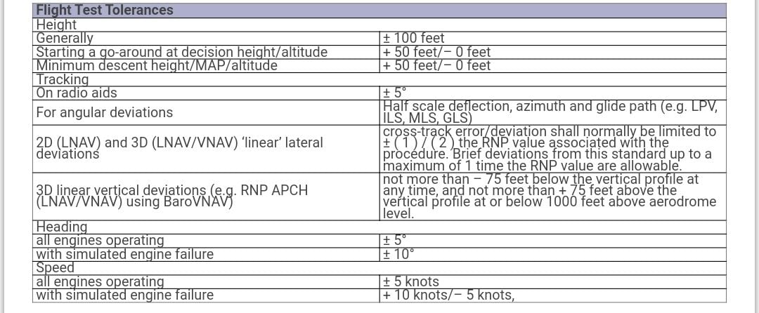
Trying, in vain, to find out what the deviation limits are for non-precision approaches; anecdotally learned (years ago) that the NDB limit (safety lane?) was +/- 5 degrees, are VOR approaches etc the same?

Joined: Dec 2005
Aviation Qualifications: ATPL
Posts: 4,978
Likes: 329
From: Hong Kong
Consider the limit as more of a guideline. In challenging conditions the examiner will give you extra leeway. The important thing is to recognise that you're left/high/fast etc and correct. Aim for perfection and miss.


Joined: Oct 1999
Aviation Qualifications: ATPL
Posts: 7,373
Likes: 931
From: Den Haag
Or, do you mean the actual procedure design tolerances? A bit of light reading here: https://skybrary.aero/sites/default/...shelf/5801.pdf
Joined: Feb 2003
Posts: 541
Likes: 336
From: Blue sky
Not an examiner, but as an instructor the applied rule has always been �max deviation is half scale deflection�. This equates to 5� for a VOR. This is also a stable approach criteria on final.
Last edited by BraceBrace; 4th March 2024 at 15:47.

Joined: May 2006
Posts: 54
Likes: 1
From: UK
ADF has errors of up to +/- 5 degrees thus 5 degrees off indicated could actually be 10 degrees off. Safety lane as you call it (surveyed approach area) is +/- 10 degrees. Thus greater than +/- 5 could put you outside of the safe area. Trouble is, could also put you more or less on centre line! Don’t you just love an NDB approach.
By the way, I once had to fly an asymmetric NDB approach to minimums for real. Deep joy!
By the way, I once had to fly an asymmetric NDB approach to minimums for real. Deep joy!

Joined: Oct 2017
Posts: 852
Likes: 22
From: Bressuire
Consider the limit as more of a guideline. In challenging conditions the examiner will give you extra leeway. The important thing is to recognise that you're left/high/fast etc and correct. Aim for perfection and miss.
Joined: Aug 2001
Posts: 696
Likes: 10
From: Shropshire
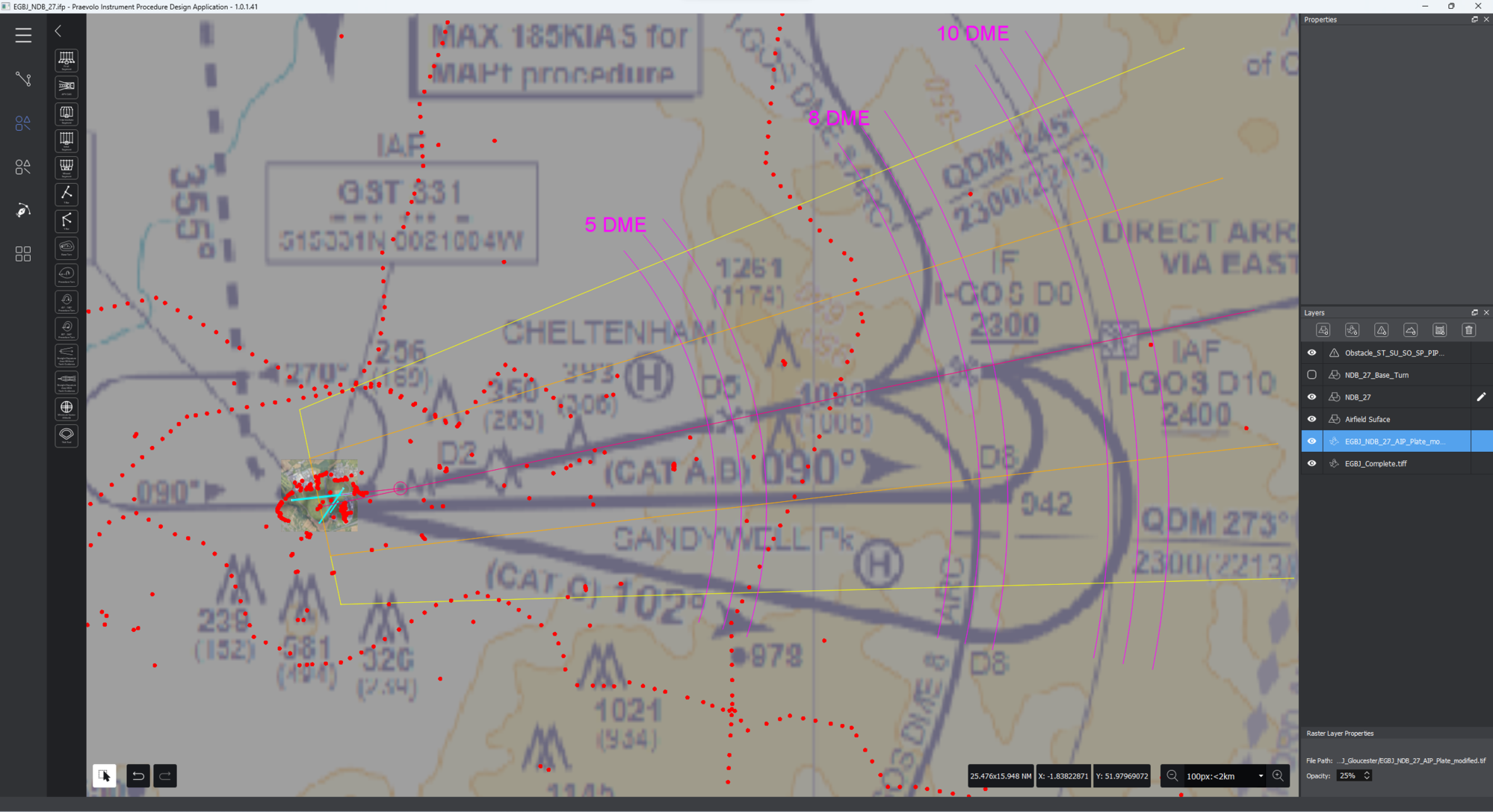
I'm not sure whether the attached image will be of help or interest for anyone. I've overlaid a construction of the protection areas for the NDB approach to Runway 27 at Gloucester EGBJ.
At the GST NDB on the airfield, a semi-width of 1.25 NM (it would be 1.0 NM for a VOR) extends out each side of the approach centreline; the inner half of each semi-width (shown in orange) defines the start of the primary protection area, the outer half of each semi-width (Shown in yellow) defines the start of the secondary protection area.
Each secondary area outer edge then diverges from the centreline at an angle of 10.3� (it would be 7.8� for a VOR) . At the same time the primary areas diverge so that the width of the primary and secondary areas, when measured perpendicular to the centerline, remain equal.
Within the primary area, bounded by the orange lines, a minimum obstacle clearance (MOC) is maintained at 300 m (984 ft) until the IF at 8 DME where the MOC reduces to 150 m (492 ft) until the FAF where the MOC reduces to 76 m (246 ft). In the secondary area, the MOC starts at the same value as the adjacent primary area and reduces linearly to zero at the outer boundary of the secondary area.
Cheers
TeeS
Last edited by TeeS; 15th March 2024 at 07:54. Reason: Correcting stupidity!
Joined: Dec 2001
Posts: 1,471
Likes: 848
From: Here 'n' there!
ATC:- "C/S, have you got a problem up there?!!!!" as, clearly, I was not quite where ATC expected me to be - all I could see was a screen and a drunken needle!
I looked over at the examiner who smiled and then keyed the mic - "No, we're fine ...... but your NDB definitely has a problem!!!"

Of course, in normal line flying we used the NDB backed up by GPS (no GPS approach available) ................................ officially!!!!!!!!

Joined: May 2006
Posts: 54
Likes: 1
From: UK
I'm not sure whether the attached image will be of help or interest for anyone. I've overlaid a construction of the protection areas for the NDB approach to Runway 27 at Gloucester EGBJ.
At the GST NDB on the airfield, a semi-width of 1.25 NM (it would be 1.0 NM for a VOR) extends out each side of the approach centreline; the inner half of each semi-width (shown in orange) defines the start of the primary protection area, the outer half of each semi-width (Shown in yellow) defines the start of the secondary protection area.
Each secondary area outer edge then diverges from the centreline at an angle of 10.3� (it would be 7.8� for a VOR) . At the same time the primary areas diverge so that the width of the primary and secondary areas, when measured perpendicular to the centerline, remain equal.
Within the primary area, bounded by the orange lines, a minimum obstacle clearance (MOC) is maintained at 300 m (984 ft) until the IF at 8 DME where the MOC reduces to 150 m (492 ft) until the FAF where the MOC reduces to 76 m (246 ft). In the secondary area, the MOC starts at the same value as the adjacent primary area and reduces linearly to zero at the outer boundary of the secondary area.
Cheers
TeeS
At the GST NDB on the airfield, a semi-width of 1.25 NM (it would be 1.0 NM for a VOR) extends out each side of the approach centreline; the inner half of each semi-width (shown in orange) defines the start of the primary protection area, the outer half of each semi-width (Shown in yellow) defines the start of the secondary protection area.
Each secondary area outer edge then diverges from the centreline at an angle of 10.3� (it would be 7.8� for a VOR) . At the same time the primary areas diverge so that the width of the primary and secondary areas, when measured perpendicular to the centerline, remain equal.
Within the primary area, bounded by the orange lines, a minimum obstacle clearance (MOC) is maintained at 300 m (984 ft) until the IF at 8 DME where the MOC reduces to 150 m (492 ft) until the FAF where the MOC reduces to 76 m (246 ft). In the secondary area, the MOC starts at the same value as the adjacent primary area and reduces linearly to zero at the outer boundary of the secondary area.
Cheers
TeeS
Joined: Aug 2001
Posts: 696
Likes: 10
From: Shropshire
If you are responding to me, I'm not sure I asked any question for which an answer is required.
With respect to your previous statement of " Safety lane as you call it (surveyed approach area) is +/- 10 degrees", I have to ask, if the 'safety lane' is +/- 10� then what is the 'safety lane' width when you cross the beacon?
PANS-OPS is ICAO Doc 8168, and Volume II is the relevant part covering 'Construction on Visual and Instrument Flight Procedures'.
Cheers
TeeS
Joined: Oct 2018
Posts: 414
Likes: 42
From: South West
It's appendix 7 to Part FCL (IR skills test). Tracking of radio aids is 5 degrees. There are similar references in each of the type of skill tests/proficiency checks. The IMC rating test (STDs Doc 25(A) says 10 degrees for ADF with is oddly generous.