


Open-loop FBW vs Close-loop FBW

Thread Starter
Joined: Apr 2025
Posts: 30
Likes: 0
From: Milky Way Galaxy
Open-loop FBW vs Close-loop FBW
Hello everyone,
Can someone pls explain to me how exactly does open-loop fly-by-wire work? I keep mixing it with Boeing's C*U fly-by-wire logic, how is it different from Boeing's C*U FBW control laws? From what I understand, an open-loop FBW system is kind of similar to Boeing's C*U FBW control laws, in a sense that it kind of "replicates" the mechanical feel of a hydraulic aircraft. Also, in open loop system, the FCC does not provide a feedback loop to keep the flight conditions similar to the pilot's original input (tho Idk if Boeing's C*U does that or not).
Here's a quote, "In the open-loop FBW, the displacement of the control column is transferred into an equivalent movement of the aircraft’s elevator, Unlike a traditional hydraulic system, there is a variable control gain unit in the loop which lowers loop gain at higher speed, but there is no adjustment of the elevator displacement based on how the aircraft reacts in pitch. There is no system feedback loop."
How is this different from Boeing's C*U FBW logic? Shouldn't C*U be classified as an open-loop fbw then?
From what I understand, the way it works is open-loop <--> C*U (kind of like an intermediate between Airbus's C* and Embraer E1's open-loop FBW) <--> AIrbus's C* FBW law. To me, it seems like the C*U is kind of like an intermediate between an open-loop fbw and C*.
Here are some of my questions regarding this system:
1) Why is the C*U FBW logic on the Boeing considered a closed-loop FBW system instead of an open loop?
2) Why did Embraer (which used an open-loop FBW system on the E1) switch to a closed-loop system on the E2?
3) Theoretically, would it be hard to implement an open-loop fbw system on an aircraft that used a sidestick with 0 force feedback (basically a very typical fbw sidestick with an electric trim switch maybe)
4) (Elaborating on Q3) Lets say I want to implement an open-loop fbw system on an aircraft, would it be absolutely necessary that I would also have also implement a force-feedback system for it to be effectively used by pilots. (Basically, can I implement an open loop fbw system on an aircraft that has a typical airbus-style side stick and no force feedback)?
Last edited by 777Supremecist; 11th February 2026 at 06:29.


Joined: Sep 2016
Posts: 936
Likes: 67
From: USA
Closed loop is like your car's cruise control: It compares the actual speed to the desired speed, and loops that difference back to the throttle control to undo whatever happened (surface roughness, low tire pressure, up/downslope, etc.) to cause the difference to be anything other than zero. Over and over again.
Open loop (meaning really, no loop) is if you set the throttle pedal in some position with a clamp, to set the speed you want. In a certain condition that speed will hold, but in any other condition (the surface roughness and other things) it will go faster or slower, and the car will neither detect nor do anything about that.
Airbus "direct law" is open loop. The elevator just goes in the position matching the stick, and that's it. It replicates cable and pulley.
C* and C*U are both closed loop (actually, it's a few loops, each handling different parameters, stacked in certain ways). C*U has everything that C* has, and in addition has a loop that continuously drives airspeed difference from trim speed to zero. Think of it as if with the autopilot off, FLCH or Open climb/descent is still on, and you're setting the speed with the trim switch (instead of MCP). The inner loop is running and killing attitude fluctuations, and the outer loop is simultaneously running on top of that, killing speed deviations.
Last edited by Vessbot; 10th February 2026 at 22:28.
Joined: Sep 2016
Posts: 936
Likes: 67
From: USA
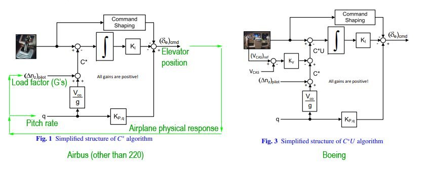
https://www.icas.org/icas_archive/IC...PAPERS/605.PDF Here's an interesting document that goes into this stuff, but at a super high level. I've taken the relevant part for this discussion, the simplified (hah!) diagrams of the C* and C*U laws. There's some extraneous stuff in there, but I added some explanations in green, as well as the arrows representing what happens as a result of the elevator position, feeding back toward the detectable parameters by sensors on the airplane, that actually forms it into a loop.
Notice the Boeing one is the same as the Airbus one, with the addition of (Vcas)ref (the trim airspeed set by the trim switch on the yoke), being compared to Vcas (the actual airspeed)... and then that feeds in to the rest to be subtracted against and the difference zeroed out. (Also note that "q" here means not dynamic pressure, but pitch rate.)
Notice the Boeing one is the same as the Airbus one, with the addition of (Vcas)ref (the trim airspeed set by the trim switch on the yoke), being compared to Vcas (the actual airspeed)... and then that feeds in to the rest to be subtracted against and the difference zeroed out. (Also note that "q" here means not dynamic pressure, but pitch rate.)
Last edited by Vessbot; 11th February 2026 at 17:09.
Thread Starter
Joined: Apr 2025
Posts: 30
Likes: 0
From: Milky Way Galaxy
https://www.icas.org/icas_archive/IC...PAPERS/605.PDF Here's an interesting document that goes into this stuff, but at a super high level. I've taken the relevant part for this discussion, the simplified (hah!) diagrams of the C* and C*U laws. There's some extraneous stuff in there, but I added some explanations in green, as well as the arrows representing what happens as a result of the elevator position, feeding back toward the detectable parameters by sensors on the airplane, that actually forms it into a loop.
Notice the Boeing one is the same as the Airbus one, with the addition of (Vcas)ref (the trim airspeed set by the trim switch on the yoke), being compared to Vcas (the actual airspeed)... and then that feeds in to the rest to be subtracted against and zeroed out. (Also note that "q" here means not dynamic pressure, but pitch rate.)
Notice the Boeing one is the same as the Airbus one, with the addition of (Vcas)ref (the trim airspeed set by the trim switch on the yoke), being compared to Vcas (the actual airspeed)... and then that feeds in to the rest to be subtracted against and zeroed out. (Also note that "q" here means not dynamic pressure, but pitch rate.)
Thread Starter
Joined: Apr 2025
Posts: 30
Likes: 0
From: Milky Way Galaxy
Closed loop is like your car's cruise control: It compares the actual speed to the desired speed, and loops that difference back to the throttle control to undo whatever happened (surface roughness, low tire pressure, up/downslope, etc.) to cause the difference to be anything other than zero. Over and over again.
Open loop (meaning really, no loop) is if you set the throttle pedal in some position with a clamp, to set the speed you want. In a certain condition that speed will hold, but in any other condition (the surface roughness and other things) it will go faster or slower, and the car will neither detect nor do anything about that.
Airbus "direct law" is open loop. The elevator just goes in the position matching the stick, and that's it. It replicates cable and pulley.
C* and C*U are both closed loop (actually, it's a few loops, each handling different parameters, stacked in certain ways). C*U has everything that C* has, and in addition has a loop that continuously drives airspeed difference from trim speed to zero. Think of it as if with the autopilot off, FLCH or Open climb/descent is still on, and you're setting the speed with the trim switch (instead of MCP). The inner loop is running and killing attitude fluctuations, and the outer loop is simultaneously running on top of that, killing speed deviations.
Open loop (meaning really, no loop) is if you set the throttle pedal in some position with a clamp, to set the speed you want. In a certain condition that speed will hold, but in any other condition (the surface roughness and other things) it will go faster or slower, and the car will neither detect nor do anything about that.
Airbus "direct law" is open loop. The elevator just goes in the position matching the stick, and that's it. It replicates cable and pulley.
C* and C*U are both closed loop (actually, it's a few loops, each handling different parameters, stacked in certain ways). C*U has everything that C* has, and in addition has a loop that continuously drives airspeed difference from trim speed to zero. Think of it as if with the autopilot off, FLCH or Open climb/descent is still on, and you're setting the speed with the trim switch (instead of MCP). The inner loop is running and killing attitude fluctuations, and the outer loop is simultaneously running on top of that, killing speed deviations.
Also, I thought the Airbus fcc still maintains path stability in direct law, right?
Joined: Sep 2016
Posts: 936
Likes: 67
From: USA
Actually, probably the feeling that you're getting at is that the outer loop (speed) disturbs what the inner loop (blend of G and pitch rate) is holding. Only what the outermost loop commands, is ultimately held. The inner loop works in service to the outer loop. This way, a gust that disturbs the pitch rate, can be reacted to by that loop at the appropriate (quick) rate at the short period mode while giving the other loop a stable platform from which to act, which is much slower against speed. If there was only a speed loop, then it would either wallow forever (if acting slow), or pitch back and forth in multiple overcorrections (if acting fast.) It couldn't react to the separate parameters at their own rates simultaneously.
Also, I thought the Airbus fcc still maintains path stability in direct law, right?
Last edited by Vessbot; 11th February 2026 at 14:31.
Joined: Sep 2017
Aviation Qualifications: Non-Aircrew
Posts: 1,025
Likes: 1,057
From: Bremen
Only in a very general manner of speaking. It reacts directly to a blend of G and pitch rate (this blend called C*), which results in a path. And it doesn't hold a pitch, it only zeroes out the rate. So if a big gust moves the pitch (wasn't successfully cancelled), then it stays at the new pitch.
Joined: Sep 2016
Posts: 936
Likes: 67
From: USA
Thread Starter
Joined: Apr 2025
Posts: 30
Likes: 0
From: Milky Way Galaxy
Only in a very vague manner of speaking. It reacts directly to a blend of G and pitch rate (this blend called C*), which results in a path, as a consequence. And it doesn't hold a pitch, it only zeroes out the rate. So if a big gust moves the pitch (wasn't successfully cancelled), then it stays at the new pitch.
For example, in a hydraulic aircraft, the aerodynamic effect that your input is going to have in the airplane, its not the movement of the yoke but the force on it which tells you whether you will over stress the airframe. At low speeds you will instinctively push or pull to obtain a given pitch rate, at higher speeds you will modulate stick forces to obtain a g load. The yoke will (naturally) be stiff and more sensitive at higher speeds, and vice versa for lower speeds
How does it work for Airbus's direct law, in a side stick with no pressure feedback??

Joined: Jan 2025
Aviation Qualifications: Non-Aircrew
Posts: 639
Likes: 775
From: New Zealand
Speaking of which, a bit off topic, but how does Airbus's direct law work? In direct law, does the stick deflection actually use a blend of pitch and g rate (C*) or does it correspond directly to elevator deflection? If the case is the latter, isn't that a bit risky? As the pilot might overstress the airframe by pulling too hard at a higher speed etc/
For example, in a hydraulic aircraft, the aerodynamic effect that your input is going to have in the airplane, its not the movement of the yoke but the force on it which tells you whether you will over stress the airframe. At low speeds you will instinctively push or pull to obtain a given pitch rate, at higher speeds you will modulate stick forces to obtain a g load. The yoke will (naturally) be stiff and more sensitive at higher speeds, and vice versa for lower speeds.
Rudder travel limiters are very similar I believe - there was an ATR runway excursion a while back where the automatic travel limiter stayed in the high-speed position due to electrical failure, and the crew lost directional control on rollout.
Joined: Jan 2025
Aviation Qualifications: Non-Aircrew
Posts: 639
Likes: 775
From: New Zealand
To quote from an early 777 FCOM:
And 767:
The ELEV FEEL COMPUTER (may be mechanical?) is shown receiving pitot pressure.
In secondary and direct modes, the elevator variable feel system provides two feel
force levels instead of a continuous variation with airspeed. The force levels
change with flap position. With the flaps up, the feel forces provide maneuver
force levels that discourage overcontrol in the pitch axis at high speeds. With flaps
extended (flaps 1 or greater), the feel forces decrease to provide force levels
appropriate for approach and landing.
In the secondary and direct modes, both the primary pitch trim switches and the
alternate pitch trim levers move the stabilizer directly. There is no trim reference
speed.
Two elevator feel systems provide artificial feel forces to the pilots control
columns. Mechanical springs provide feel following a loss of the left and center
hydraulic systems.
columns. Mechanical springs provide feel following a loss of the left and center
hydraulic systems.
Last edited by Someone Somewhere; 14th February 2026 at 02:39.
Joined: Sep 2016
Posts: 936
Likes: 67
From: USA
Speaking of which, a bit off topic, but how does Airbus's direct law work? In direct law, does the stick deflection actually use a blend of pitch and g rate (C*) or does it correspond directly to elevator deflection? If the case is the latter, isn't that a bit risky? As the pilot might overstress the airframe by pulling too hard at a higher speed etc/


