


Vmc

Thread Starter

Joined: Mar 2005
Aviation Qualifications: Military
Posts: 6,563
Likes: 952
From: Aus
Vmc
looking at the TCDS for the Gulfstream 1 it has a Vmc of 101 knots with the prop feathered, gear up and take off flap. If flap is then retracted the Vmc increases to 113 knots. Why?


Joined: Apr 2015
Posts: 44
Likes: 13
From: Glasgow, EGPF
According to CS-25, the only relation to stall speed is that Vmc may not be greater than 1.13 Vsr. So that doesn’t explain it.
More likely is that the drag of the flaps is behind the CofG and so improves directional stability.
caveat that I realise I should be looking at the certification requirements at the time of design, but I doubt they would have removed such a fundamental constraint.
More likely is that the drag of the flaps is behind the CofG and so improves directional stability.
caveat that I realise I should be looking at the certification requirements at the time of design, but I doubt they would have removed such a fundamental constraint.

Joined: Aug 2007
Posts: 59
Likes: 64
From: UK
Flaps down = more overall drag so less asymmetry from the drag of the windmilling prop. Flaps down also tends to be directionally stabilising. Flaps down = lower angle of attack for a given speed and weight, so lower p-factor.


Joined: Jan 2008
Posts: 162
Likes: 8
From: Scotland
When an engine fails you are using the rudder to create an aerodynamic force to counteract the yaw from asymmetric trust. To create more force you either need larger deflection or higher airflow/speed.
Propellor slipstream can create more drag when flaps are deployed, the increased drag would be on the live engine side with one engine out. That drag would counteract the yaw from asymmetric trust, therefore you need less rudder or speed to create the same force. So with one engine and take-off flaps the asymmetric force is less, than with flaps up.
As rudder deflection is limited by it's stops, when an engine fails with flaps and you use full rudder you would create the required force at a lower speed. When you raise the flaps, you create more asymmetry, with the rudder at the stop only way of creating more force is by increasing speed.
Joined: Oct 2004
Posts: 255
Likes: 15
From: australia
Couple of things to consider.
1. Certification basis - what amendment status of CAR4b? This is important as the rudder force could be 180lb and the stall speed reference 1.2Vs. Where Vs is the minimum speed in the stall. This is clearly related to V2 minimum. IIRC the rudder forces changed (150 lbf) with amendment 42 to FAR25.
2. The CAR4b Vmc requirement was for take-off flap, I don't recall flaps 0 as a take-off flap when I flew G1's, but that was over 40 years ago. should be in the TCDS. If flap 0 is not a take-off flap, by definition the speed is not really a Vmc.
3. You have no way of knowing if Vmc was determined by a dynamic test or the static test, the test method could have been different in each case. At some stage there were 3 methods of establishing Vmc in CAR4b - don't know if this applied to the G159 certification basis.
4. There should be a windmilling Vmc as well.
5. The applicant may decide that a particular speed will not be performance limiting for Vmc and do the minimum testing to establish that this speed is compliant.
Last edited by zzuf; 4th July 2024 at 04:44.
Thread Starter
Joined: Mar 2005
Aviation Qualifications: Military
Posts: 6,563
Likes: 952
From: Aus
There should be a windmilling Vmc as well
Joined: Oct 2004
Posts: 255
Likes: 15
From: australia
Seems to imply that flaps 0 is a take-off setting?
Joined: Sep 2002
Posts: 2,188
Likes: 6
From: La Belle Province
A couple of things.
Re: "no definition of takeoff flap" - there probably is such a definition, explicit or implied, in the Airplane Flight Manual; you can't read the TCDS in isolation.
re Stall speed effect on VMC. There's nothing explicit in the regulations linking VMC and Vs - they both then impact operational speeds independently. But there is an effect of the lifting capability of the wing on VMC - simply, if you can't maintain level flight you can't demonstrate VMC, and it was all about demonstration back then. So even if there is theoretically enough control power at lower speeds, you can't have a VMC below a certain speed, regardless.
re flaps effect on VMC - there's also (sometimes) a directional stability effect of having flaps down (more flaps = more directional stability) - this then can help in a VMC condition as the helping effect of directional stability is why the bank into the live engine is helping. So a higher VMC with less flaps could work.
Joined: Oct 2004
Posts: 255
Likes: 15
From: australia
A couple of things.
Re: "no definition of takeoff flap" - there probably is such a definition, explicit or implied, in the Airplane Flight Manual; you can't read the TCDS in isolation.
re Stall speed effect on VMC. There's nothing explicit in the regulations linking VMC and Vs - they both then impact operational speeds independently. But there is an effect of the lifting capability of the wing on VMC - simply, if you can't maintain level flight you can't demonstrate VMC, and it was all about demonstration back then. So even if there is theoretically enough control power at lower speeds, you can't have a VMC below a certain speed, regardless.
re flaps effect on VMC - there's also (sometimes) a directional stability effect of having flaps down (more flaps = more directional stability) - this then can help in a VMC condition as the helping effect of directional stability is why the bank into the live engine is helping. So a higher VMC with less flaps could work.
Re: "no definition of takeoff flap" - there probably is such a definition, explicit or implied, in the Airplane Flight Manual; you can't read the TCDS in isolation.
re Stall speed effect on VMC. There's nothing explicit in the regulations linking VMC and Vs - they both then impact operational speeds independently. But there is an effect of the lifting capability of the wing on VMC - simply, if you can't maintain level flight you can't demonstrate VMC, and it was all about demonstration back then. So even if there is theoretically enough control power at lower speeds, you can't have a VMC below a certain speed, regardless.
re flaps effect on VMC - there's also (sometimes) a directional stability effect of having flaps down (more flaps = more directional stability) - this then can help in a VMC condition as the helping effect of directional stability is why the bank into the live engine is helping. So a higher VMC with less flaps could work.
I am not sure what your point is with reference to Vmc and stall, as far as CAR4b is concerned Vmc is not to be greater than 1.2 Vs. I am aware that other takeoff speeds have a Vmc additive, my opinion on Vmc and V2 minimum was that it is not unreasonable to have both limited by 1.2 Vs.
I am also aware that the Vmc determination for the original Fokker F28 was done in a less than 1g flight path hence lower than 1g stall speed. While I don't know why this was done, Fokker and the regulatory authority may have been very conservative about flying around at close to stall speed in an early T tailed jet. The F28 had an artificial stall identification, (also artificial stall warning), there may have been concerns about the stall ident accuracy with sideslip - who knows, but a less than 1g flight path would be an easy test to perform if one worked up to the final test points.
Your point about banking towards the operating engine can use the aircraft directional stability to assist in directional control, is well made - just make sure the bank angle is sufficent to ensure that the sideslip is toward the operating engine.
Extract from a report I wrote many years ago is instructive:
Further from my Canberra Asymmetric Handling Report
Determination of Minimum Control Speed
4.3 Minimim control speed was determined by reducing speed from the minimum trim speed in a straight climb at between 4,000 and 5,000 feet (first cut). The minimum control speed was the lowest speed at which a straight climb could be maintained. These test were made with power settings of 7600 RPM and 7850 RPM on the "live" engine and at bank angles of 0 degrees and 5 degrees towards this engine. Rudder pedal forces measured during these tests were very high and difficult to hold for even a short period.
4.3.3 Minimum Control Speed 7850 RPM Wings Level
Using the technique described in para 4.3 the minimum control speed with the right engine set at 7850 RPM was 175k IAS. The rudder pedal position was full right rudder held by a force of 250lbf. At 175kIAS the slipball was about 1/2 width to the right and the sideslip angle was 3 degrees left. Aileron forces were zero with the yoke position at 10 degrees left and the aileron trimmer position at 2 unit left.
4.3.4 Minimum Control Speed 7850 RPM 5 Degrees Right Bank
With 5 degrees of bank towards the live engine, the speed was reduced to 150k IAS before the aircraft commenced a slow turn to the left. The rudder force was still 250 lbf right rudder and a slight rudder buffet became apparent. The yoke and aileron trimmer positions were 5 degrees and 4 units right respectively.
The sideslip angle was 5 degrees right and the slip ball was at 1/2 the total available travel to the right.
Comment
This is clearly not Vmc - rudder forces way beyond the then BCARD limits.
No CAS quoted - no PEC info with sideslip.
At some bank anle between 0 degrees and 5 degrees right the sideslip direction changed from left to right - at some small angle of bank the sideslip angle was zero.
Bank angle was extremely powerful in reducing the minimum control speed
Fleet Manager

Joined: Apr 2001
Aviation Qualifications: ATPL
Posts: 7,445
Likes: 310
From: various places .....
Bank angle was extremely powerful in reducing the minimum control speed
You probably would recall from a short course around 30 years or so ago, SR related the tale of a certain large aeroplane with more engines than a young chap like me could comprehend, where the Vmc increased somewhere around 40-odd knots if the bank were to be applied the "wrong" way ?
You probably would recall from a short course around 30 years or so ago, SR related the tale of a certain large aeroplane with more engines than a young chap like me could comprehend, where the Vmc increased somewhere around 40-odd knots if the bank were to be applied the "wrong" way ?
Thread Starter
Joined: Mar 2005
Aviation Qualifications: Military
Posts: 6,563
Likes: 952
From: Aus
zzuf, located a flight manual, flaps were four position fowlers,
UP 0�
TAKE OFF 12-1/2�
APPROACH 20�
FULL 33�
No performance charts included but all mention of take off includes use of take off flap, being fowlers I guess it figures, increase of wing area with little addition to drag.
UP 0�
TAKE OFF 12-1/2�
APPROACH 20�
FULL 33�
No performance charts included but all mention of take off includes use of take off flap, being fowlers I guess it figures, increase of wing area with little addition to drag.
Joined: Oct 2004
Posts: 255
Likes: 15
From: australia
zzuf, located a flight manual, flaps were four position fowlers,
UP 0�
TAKE OFF 12-1/2�
APPROACH 20�
FULL 33�
No performance charts included but all mention of take off includes use of take off flap, being fowlers I guess it figures, increase of wing area with little addition to drag.
UP 0�
TAKE OFF 12-1/2�
APPROACH 20�
FULL 33�
No performance charts included but all mention of take off includes use of take off flap, being fowlers I guess it figures, increase of wing area with little addition to drag.
Does the AFM Vmc data tie up with the TCDS?
Thread Starter
Joined: Mar 2005
Aviation Qualifications: Military
Posts: 6,563
Likes: 952
From: Aus
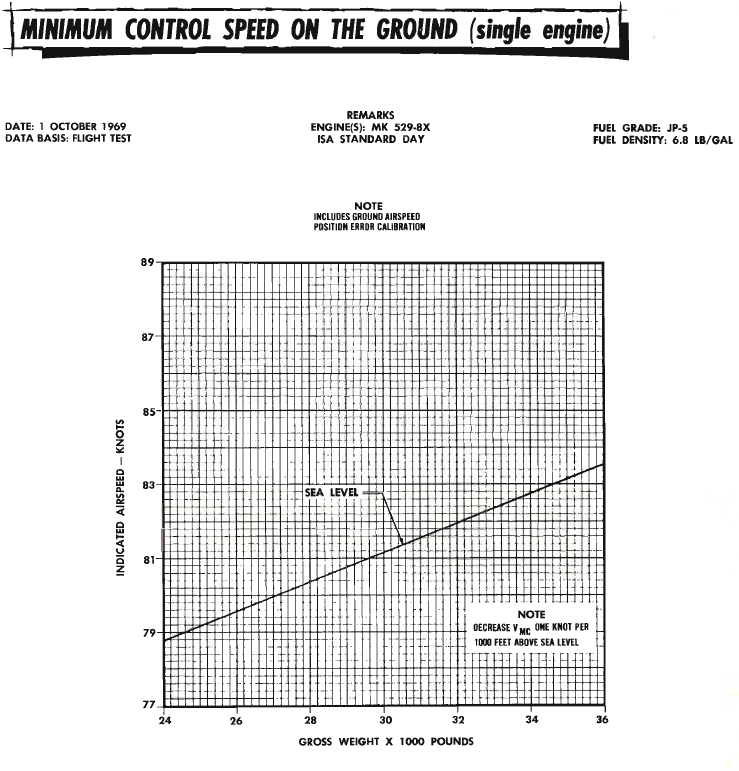
zzuf, Have got hold of a NATOPS manual for the aircraft, there is no chart for Vmc values, other than a statement that 138 knots is Vmc clean with windmilling prop. A further statement as follows,
the only minimum control speed chart is for on ground.
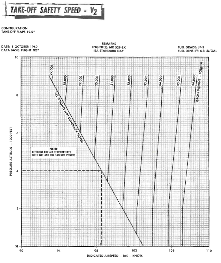
V2 speed is the take off safety speed. V2 is the optimum single engine climb speed (gear up, take off flap setting, prop feathered) and is the greater of the following;
1. 1.2 times the zero thrust stalling speed with the wing flaps in the take off position
2. 1.1 times the air minimum control speed
1. 1.2 times the zero thrust stalling speed with the wing flaps in the take off position
2. 1.1 times the air minimum control speed
Last edited by megan; 21st July 2024 at 03:09.
