


A320 THS drive

Thread Starter
Join Date: Jan 2006
Location: Between a rock and a hard place
Posts: 1,267
Likes: 0
Received 0 Likes
on
0 Posts
A320 THS drive
I can’t really get my head around the way the THS (stabilizer) drive is described in the CBT material. I understand the screwjack is driven by hydraulic motors but it then goes on to say for Auto Pitch Trim system, the hydraulic motors are driven by one of three eletric motors.
I can more comprehend the design if the electric motors control, i.e. position directional valves, the hydraulic motors (which the CBT indeed later hint also). Any A320 tech. could confirm my suspicion that electrics control, rather than drive (as in: apply torque), the hydraulic motors?
I can more comprehend the design if the electric motors control, i.e. position directional valves, the hydraulic motors (which the CBT indeed later hint also). Any A320 tech. could confirm my suspicion that electrics control, rather than drive (as in: apply torque), the hydraulic motors?

Join Date: Mar 2006
Location: Vance, Belgium
Age: 62
Posts: 271
Likes: 0
Received 5 Likes
on
3 Posts
https://assets.publishing.service.go...EZWX_03-17.pdf
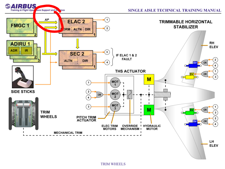
This image helps understand the link from the 3 electric motors to the 2 hydraulic actuators:
This one is more for the servo loops

Stabiliser system description
The horizontal stabiliser is controlled by the THSA and it can be trimmed either electrically or manually with a trim wheel in the cockpit via the THSA. The electrical trim is, by default, controlled by ELAC 2 and if ELAC 2 detects that the system is not responding to its commands it will hand over control to ELAC 1. If both ELAC 2 and 1 detect that the stabiliser is not following their commands then control of the stabiliser will be handed over to spoiler elevator computer 2 (SEC 2) followed by SEC 1 if the same fault is detected by each respective SEC.
The ELAC sends commands to the THSA via the pitch trim actuator (PTA) which contains three electric motors, which control the two hydraulic motors that drive the stabiliser ball screwjack. An override mechanism downstream of the PTA allows the manual trim wheel in the cockpit to override any inputs from the PTA to the hydraulic motors. The commanded stabiliser position is measured by the COM transducer which contains three RVDTs2 . A mini reduction gear assembly mechanically transmits the commanded stabiliser position to the COM transducer. A separate MON transducer measures the position of the stabilizer ball screwjack. The ELACs monitor both the COM and MON transducers and if there is a discrepancy the ‘stab jam’ message will be annunciated and stabiliser movement will cease.
Footnote 2 An RVDT is a Rotary Variable Differential Transformer which is used to measure a rotating position.
This one is more for the servo loops
Last edited by Luc Lion; 21st Nov 2023 at 14:18.
Join Date: Sep 2011
Location: FL390
Posts: 239
Likes: 0
Received 0 Likes
on
0 Posts
This is why it sometimes seems like they're unnatural to read, because the very specific English word that is a direct translation doesn't exist in the set of allowed words, so they need to find a different way of saying it.
So, just to see if I understand this;
The three electric motor(s), or the cockpit trim wheels physically move a reference block, whose position is measured. This position is compared to the position of the THS joint on the screw jack.
If there is a difference, the two hydraulic motors are commanded to move via electronics until the two positions are coincident.
So, the three electric motors do not move the hydraulic motor valves, they only move the trim reference block, and the hydraulic valves controlling the hydraulic motors are modulated by other means?
Have I got that right ?
Join Date: Feb 2023
Location: Aachen
Posts: 34
Likes: 0
Received 0 Likes
on
0 Posts
So, just to see if I understand this;
The three electric motor(s), or the cockpit trim wheels physically move a reference block, whose position is measured. This position is compared to the position of the THS joint on the screw jack.
If there is a difference, the two hydraulic motors are commanded to move via electronics until the two positions are coincident.
So, the three electric motors do not move the hydraulic motor valves, they only move the trim reference block, and the hydraulic valves controlling the hydraulic motors are modulated by other means?
Have I got that right ?
The three electric motor(s), or the cockpit trim wheels physically move a reference block, whose position is measured. This position is compared to the position of the THS joint on the screw jack.
If there is a difference, the two hydraulic motors are commanded to move via electronics until the two positions are coincident.
So, the three electric motors do not move the hydraulic motor valves, they only move the trim reference block, and the hydraulic valves controlling the hydraulic motors are modulated by other means?
Have I got that right ?
Simon
Join Date: Feb 2023
Location: Aachen
Posts: 34
Likes: 0
Received 0 Likes
on
0 Posts
Glad I could help 
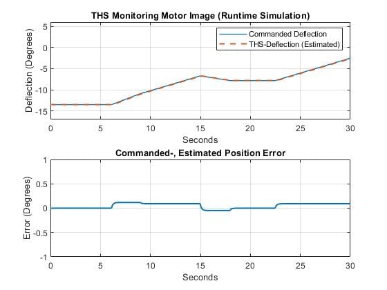
I attached a plot of the response of the THS model implemented on the SECs to monitor the true THS position. Maybe this gives an impression on how the system reacts to trim inputs. In this case obviously from the electrical motors. Should be the same though for manual trimming.
The commanded deflection comes directly out of the C*law and is then fed into the model which estimates the real postion (where the THS should be).
A little reminder: The data shown below comes right out of the real algorithms "emulated" in a other programming language to visualize/plot what's going on. Should be what's happening in reality, but these are NO official Airbus charts!
Simon
Ah OK, so I was in fact wrong. The motors, or the cockpit trim wheels do open the hydraulic valves, which allow pressurised fluid to drive the THS hydraulic motors to move in the appropriate direction. As the THS moves, the mechanism connected to it starts to close the hydraulic valves again, and the THS stops when the valves are fully closed, at which point it has reached the trim position commanded by the motors/trim wheel.
Can be imagined as a lever opening or closing the hydraulic valves, with one end of the lever moved by the motors, and the other end moved by the THS. Say when the lever is horizontal, the valves are closed. Moving the lever up or down via the motors or the cockpit trim wheels opens the valves, which moves the THS, which runs until the lever is horizontal again, at which point the valves are fully closed, so movement stops at the new trim position.
Got it
PS, this also explains how the THS can still be operated, (manually), in the event of complete electrical failure, as long as Green or Yellow HYD is available.
Join Date: Jul 2015
Location: Southampton
Posts: 17
Likes: 0
Received 0 Likes
on
0 Posts
This is a little unfair. The Airbus manuals were *originally* incomprehensible because of the translation from French. A few years ago Airbus became aware that this was a problem, so essentially rewrote the whole set but from a limited vocabulary of about 2000 words on the assumption that most readers wouldn't be native English speakers.
This is why it sometimes seems like they're unnatural to read, because the very specific English word that is a direct translation doesn't exist in the set of allowed words, so they need to find a different way of saying it.
This is why it sometimes seems like they're unnatural to read, because the very specific English word that is a direct translation doesn't exist in the set of allowed words, so they need to find a different way of saying it.

