


length of ILS approach

Thread Starter
Joined: Oct 2020
Posts: 13
Likes: 1
From: uk
length of ILS approach
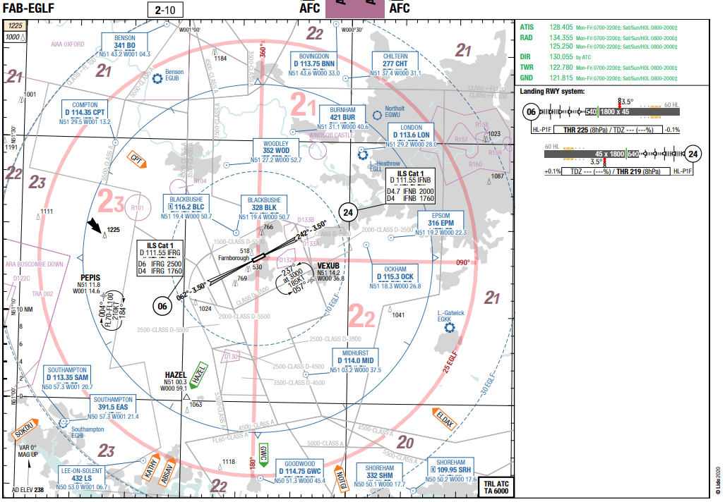
One for the planners.. What determins the length of an approach slope of an ILS approach?. Apart from the hieght above the ground from which it is started? I am looking in particular at EGLF, rwy 24 is 4.7d and 06 is 6d. I can sort of understand why 24 is short (proximity of LTMA to the east), but why is 06 longer ?

Joined: Dec 2001
Aviation Qualifications: ATPL
Posts: 3,766
Likes: 424
From: GA, USA
I am not understanding your question.
Both approach plates show a final approach fix at 4.4 DME and both have a 3.5 degree glideslope which is a little steeper then the standard 3 degrees.
https://www.platinumairways.org/files/EGLFCharts.pdf
Both approach plates show a final approach fix at 4.4 DME and both have a 3.5 degree glideslope which is a little steeper then the standard 3 degrees.
https://www.platinumairways.org/files/EGLFCharts.pdf
Only half a speed-brake

Joined: Apr 2003
Posts: 4,459
Likes: 136
From: Commuting not home
What about
Vol. II Construction of Visual and Instrument Flight Procedures
Section 4. Arrival and approach procedures
Chapter 4. Intermediate approach segment
4.2 Altitude/height selection
possibly
Chapter 5. Final approach segment
Vol. II Construction of Visual and Instrument Flight Procedures
Section 4. Arrival and approach procedures
Chapter 4. Intermediate approach segment
4.2 Altitude/height selection
possibly
Chapter 5. Final approach segment
Only half a speed-brake
Joined: Apr 2003
Posts: 4,459
Likes: 136
From: Commuting not home
The length of the intermediate approach segment shall not be ... less than 9.3 km (5.0 NM)
To fit a least the minimum I.A.S in tight airspace, obviously, the final segment might need to be shortened. OP suggested already,
More towards the question asked:
Personally (EU roots, busy hubs) I found 7, or even 9 NM more convenient. Most probably that SOPs had been built around those. One idea left at the moment = noise footprint.
To fit a least the minimum I.A.S in tight airspace, obviously, the final segment might need to be shortened. OP suggested already,
More towards the question asked:
Originally Posted by Chapter 5 FINAL APPROACH SEGMENT
5.1.3 The final approach segment should be aligned with a runway whenever possible. All final approaches with a
FAF have an optimum length of 9.3 km (5 NM). The minimum final approach segment length shall not be less than 5.6 km (3.0 NM). This value also applies to the minimum distance from the FAF to the threshold except for non-RNAV procedures constrained by existing installations. Exceptions apply
FAF have an optimum length of 9.3 km (5 NM). The minimum final approach segment length shall not be less than 5.6 km (3.0 NM). This value also applies to the minimum distance from the FAF to the threshold except for non-RNAV procedures constrained by existing installations. Exceptions apply
Personally (EU roots, busy hubs) I found 7, or even 9 NM more convenient. Most probably that SOPs had been built around those. One idea left at the moment = noise footprint.
Eidolon

Joined: May 2001
Posts: 2,244
Likes: 62
From: Some hole
Joined: Dec 2001
Aviation Qualifications: ATPL
Posts: 3,766
Likes: 424
From: GA, USA

Joined: Jun 2001
Posts: 575
Likes: 0
From: Hither and Thither
It looks to me that in this case it is for airspace containment purposes; the granted CTA's to EGLF would be as small as feasible, consistent with the purpose that the CAS is in place for in the first place. This reduces the impact on nearby aerodromes/aviation users.
The FAF being at the points where they are ensure that aircraft on the ILS will remain 500ft above the base of CAS of the various stepped down airspaces, whilst following the ILS profile down into the CTR.
Not obviously related to obstacles, as EGLF SMAC chart still has lower levels available (in theory), say if one was arriving/transitting IFR from outside CAS.
Last edited by Red Four; 26th October 2020 at 19:40. Reason: grammar


Joined: Nov 2005
Aviation Qualifications: PPL
Posts: 12,458
Likes: 368
From: Wildest Surrey
It looks to me that in this case it is for airspace containment purposes; the granted CTA's to EGLF would be as small as feasible, consistent with the purpose for the CAS is in place in the first place. This reduces the impact on nearby aerodromes/aviation users.
The FAF being at the points where they are ensure that aircraft on the ILS will remain 500ft above the base of CAS of the various stepped down airspaces, whilst following the ILS profile down into the CTR.
Not obviously related to obstacles, as EGLF SMAC chart still has lower levels available (in theory), say if one was arriving/transitting IFR from outside CAS.
I originally designed the Farnborough procedures to use alt 1,900ft as the 'platform' altitude but for some reason since I retired, the've been using a higher altitude; it was 2,400ft before CAS but what they use now I don't know.
Joined: Nov 2005
Aviation Qualifications: PPL
Posts: 12,458
Likes: 368
From: Wildest Surrey
I am not understanding your question.
Both approach plates show a final approach fix at 4.4 DME and both have a 3.5 degree glideslope which is a little steeper then the standard 3 degrees.
https://www.platinumairways.org/files/EGLFCharts.pdf
Both approach plates show a final approach fix at 4.4 DME and both have a 3.5 degree glideslope which is a little steeper then the standard 3 degrees.
https://www.platinumairways.org/files/EGLFCharts.pdf
We could have dropped the 24 glidepath to 3 deg but the Airport Director and I (then a retired Air Commodore) decided that it was best not to as we had enough trouble with NIMBYs already; if they found out that aircraft were to pass 25ft or so lower over their homes, they would have been yelling for another public inquiry.
But don't let on; I didn't tell you that anyway.
Joined: Nov 2005
Aviation Qualifications: PPL
Posts: 12,458
Likes: 368
From: Wildest Surrey
The reason for the difference is that the platform altitude on runway 06 post CAS is alt 2,500ft whereas on 24 it's 2,000ft, the '6' and '4.7' representing glidepath intercept ranges.
Avoid imitations

Joined: Nov 2000
Aviation Qualifications: ATPL
Posts: 15,115
Likes: 1,091
From: Wandering the FIR and cyberspace often at highly unsociable times
That's because I designed the procedures for a platform altitude of 1,900ft and 4.4nm equals glidepath intercept at that altitude.
We could have dropped the 24 glidepath to 3 deg but the Airport Director and I (then a retired Air Commodore) decided that it was best not to as we had enough trouble with NIMBYs already; if they found out that aircraft were to pass 25ft or so lower over their homes, they would have been yelling for another public inquiry.
But don't let on; I didn't tell you that anyway.
Joined: Apr 2010
Posts: 1,320
Likes: 102
From: IRS NAV ONLY
Jepp charts are immaterial; according to the UK Flight Safety Committee, they are not checked or regulated by an independent source, so the only definitive charts are those in the UK AIP.
Only half a speed-brake
Joined: Apr 2003
Posts: 4,459
Likes: 136
From: Commuting not home
As long as updated 3rd party package is a far fetch, and the AIP pages have all the information you'd need, it never hurts to drink from the source. It's free too.
Joined: Nov 2005
Aviation Qualifications: PPL
Posts: 12,458
Likes: 368
From: Wildest Surrey
3.5 deg GPs were adopted due to a design system called 'APATC-1' which was mandated for MOD airfields back in the '80s.
This involved a different way of calculating approach minima compared to the ICAO method used for civil airfelds, the 'dominant obsatcle' on runway 24 being --- the control tower!!
Once that was demolished in early 2003, we could have reduced to a 3 deg GP under both APATC-1 and ICAO methods of iap design.
Joined: Apr 2010
Posts: 1,320
Likes: 102
From: IRS NAV ONLY
True in real life. On the hair-splitting side: How many operators or pilots who use Jeppesen/LIDO/NavBlue charts in their flightdecks have read the small print on the Supplier's Disclaimer attachment to the sales contract?
As long as updated 3rd party package is a far fetch, and the AIP pages have all the information you'd need, it never hurts to drink from the source. It's free too.
As long as updated 3rd party package is a far fetch, and the AIP pages have all the information you'd need, it never hurts to drink from the source. It's free too.
