


Shuttle valves and differential pressure

Thread Starter

Joined: Aug 2015
Posts: 599
Likes: 61
From: ex 5Y. Now G
Shuttle valves and differential pressure
(I hope this is the appropriate place for this question - rather techy but not a/c specific)
I am looking at shuttle valves being used for handing-over pneumatic or hydraulic supplies in the event that one fails (in one interesting case, hading from a hydraulic primary supply to pneumatic stand-by supply).
They look like nice robust and simple solutions, but how are they setup in practice? If both primary and standby systems run at the same pressure, will the valve 'flutter' between the two? Or is this avoided by building-in pressure differences between each possible supply? I can see advantages and disadvantages to both. I guess there is a difference between multiple 'redundant' systems in which all are working under normal circumstances, but capable of taking-over from each other in the event of pressure loss in one, and true standby systems which sit and wait for the primary to fail and then take over.
Thanks!


Joined: Feb 2008
Posts: 114
Likes: 9
From: United Kingdom
Probably not going to be able to give a comprehensive answer here as there are many variables, such as would it be a dupicated system or a shared system (pressurised hyds on one side of the supply system and pressurised pneau on the other)? Would it be a "one - shot" emergency system or a complete alternative control system? There a a good number of other set-ups to consider too, but regarding valve flutter it would logically be held in the favoured position by a solenoid or similar, in the event of a failure it would be selected manually, or if a pressure drop occured on one side or the other then a pressure sensor should instruct to solenoid to release and yield to the system with positive pressure. The problem with that if using the same lines is that you could very easily end up dumping your air out of the same hole your fluid went out of. A pump failure would not present the same problem though, as there would be no breach of the pipework, and a wise system design would have a pump failure alarm built in as well as a pressure loss indication. I'll stop there for two reasons:
1. I could go on all night.
2. I'm almost certainly well out of date with my systems knowledge.
Others will advise better I am sure.👍
1. I could go on all night.
2. I'm almost certainly well out of date with my systems knowledge.
Others will advise better I am sure.👍
Last edited by TLDNMCL; 12th June 2019 at 18:03. Reason: Hadn't finished!

Joined: Feb 2017
Posts: 1,013
Likes: 15
From: Isla Grande
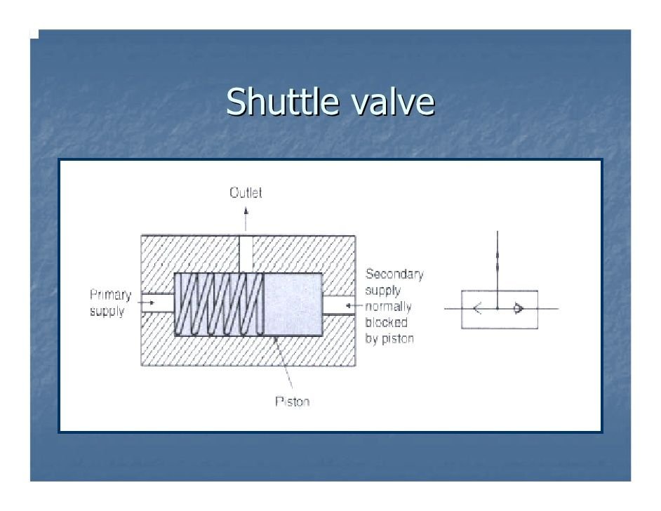
Shuttle valves in most airplane systems are "spring biased".
With even pressure from system A and B (1&2, Green&Blue, whatever) a spring or asymmetrical piston is giving priority to the normal system.
With even pressure from system A and B (1&2, Green&Blue, whatever) a spring or asymmetrical piston is giving priority to the normal system.
Joined: Jan 2009
Posts: 1,415
Likes: 432
From: Cab of a Freight Train
(I hope this is the appropriate place for this question - rather techy but not a/c specific)
I am looking at shuttle valves being used for handing-over pneumatic or hydraulic supplies in the event that one fails (in one interesting case, hading from a hydraulic primary supply to pneumatic stand-by supply).
They look like nice robust and simple solutions, but how are they setup in practice? If both primary and standby systems run at the same pressure, will the valve 'flutter' between the two? Or is this avoided by building-in pressure differences between each possible supply? I can see advantages and disadvantages to both. I guess there is a difference between multiple 'redundant' systems in which all are working under normal circumstances, but capable of taking-over from each other in the event of pressure loss in one, and true standby systems which sit and wait for the primary to fail and then take over.
Thanks!
I am looking at shuttle valves being used for handing-over pneumatic or hydraulic supplies in the event that one fails (in one interesting case, hading from a hydraulic primary supply to pneumatic stand-by supply).
They look like nice robust and simple solutions, but how are they setup in practice? If both primary and standby systems run at the same pressure, will the valve 'flutter' between the two? Or is this avoided by building-in pressure differences between each possible supply? I can see advantages and disadvantages to both. I guess there is a difference between multiple 'redundant' systems in which all are working under normal circumstances, but capable of taking-over from each other in the event of pressure loss in one, and true standby systems which sit and wait for the primary to fail and then take over.
Thanks!
Here's a rough idea how they're set up for us...Ignore the 'relayair valve' bit, that's for another device.

Thread Starter
Joined: Aug 2015
Posts: 599
Likes: 61
From: ex 5Y. Now G
Thanks, that makes a lot of sense - easy to build-in generous tolerance margins while maintaining simplicity.
Catching the downstream hole through which you also dump your standby fluid is a separate issue. I will have a poke around to see how that is typically done.
Catching the downstream hole through which you also dump your standby fluid is a separate issue. I will have a poke around to see how that is typically done.
Joined: May 2010
Posts: 443
Likes: 0
From: Boston
We utilise shuttle valves - known as "double check valves" to us - in the rail industry as a part of the locomotive pneumatic braking system. Their function is to pressurise the locomotive brake cylinders at the higher of two pressures, those sources being the train's automatic brake, or the locomotive's independent brake. With brakes released and no pressure in either system, the valve just sits there, even with identical pressures with brakes applied the small amount of inherent friction in the valve body prevents the slide from moving, it will just sit in the 'last moved to' position. I've not heard of 'valve chatter' ever being a problem and this system has been around for decades.
Here's a rough idea how they're set up for us...Ignore the 'relayair valve' bit, that's for another device.
Here's a rough idea how they're set up for us...Ignore the 'relayair valve' bit, that's for another device.
Roughly speaking this is equivalent to using 2 diodes to power a device from 2 (or more) sources,
There is no path from source to source and the higher voltage will supply the load.
The 'spring biased' effect can be achieved by using 2 diodes in series on the backup side, as long as the sources are within ~.7V of each other the primary will handle the load.
The only significant difference is that if the supplies are exactly equal both will contribute to the load.
This brings up a question on the pneumatic case , what happens when the pressures are equal, is there a chance that the shuttle will balance in the middle blocking the output?
Of course given the friction induced tendency to stay in last position greatly minimizes the chances but in theory it could happen i transient pressure were just right, an instance of Mechanical metastability?
I realize the drawings are simplified so there probably are details that prevent this.
Joined: Feb 2017
Posts: 1,013
Likes: 15
From: Isla Grande
The spring, or asymmetrical piston, will always give priority to one source...., no blocking of the output.
Thread Starter
Joined: Aug 2015
Posts: 599
Likes: 61
From: ex 5Y. Now G
Joined: May 2010
Posts: 443
Likes: 0
From: Boston
Still have a hard time looking at the schematic with the diodes pointing the 'wrong way' due to negative supplies.
One of the first integrated circuit logic families was DTL, Diode Transistor Logic
The diode analogy is probably closer since it is an analog function, higher pressure (as mediated by spring or different diameters) wins,
Of course analogies only go so far, I remember a a kid being puzzled by water analogies for electricity that never seemed to include a return path that closed the circuit.
Last edited by MurphyWasRight; 14th June 2019 at 13:28. Reason: typos
