


737MAX Stab Trim architecture

Before we hang the maintenance organisation out to dry, we really ought to wait until we know what was recorded in the tech log for those previous flights.

Join Date: Jul 2009
Location: Not far from a big Lake
Age: 81
Posts: 1,454
Likes: 0
Received 0 Likes
on
0 Posts
Can someone who works on current 737 models provide some information on the actual AOA sensors used? Some research on the subject shows that Boeing is using UTC made equipment on the 737.
I believe that they are based on a resolver principle https://en.wikipedia.org/wiki/Resolver_(electrical) , in which case there will be two AC signals coming out of each AOA sensor forming a sine and cosine signal pair that must be put together to readout the angle.
Since both right and left sensors appear to have been following the AOA, but the left sensor had a 20 degree offset, the point in the aircraft where the sine-cosine signal pair are combined before digitizing would be where to look for the source of the AOA error. Loss of either of the AC signals would create a stationary AOA reading.
I know that this is a bit technical for most people, but it might bear fruit as to the likely source of the AOA malfunction. .
@PEI: Thanks, except the second like gives me "page not found" (I read your #1650 and #1674 by scanning the page, I think that is what you were pointing to).
@Infrequent: Thanks.
@gums: copy all, nothing further, out.
Join Date: Jan 2008
Location: uk
Posts: 857
Likes: 0
Received 0 Likes
on
0 Posts
However, although SMYD implements stick shaker, it doesn't do speed trim, that is the FCC (and they got both). The text beneath that diagram shows that SMYD outputs AOA to data acquisition, but not FCC/ADIRU. FCC gets AOA from ADIRU (where it is used in speed calculation), and as far as I can see ADIRU also gets it direct from the sensor.
Pretty sure (very rusty...) that decoding resolver output for position (not angular velocity) is just a matter of relative voltage magnitude of the sin/cos signals, so wouldn't be surprising to see that duplicated. That means you'd need to have two simultaneous conversion failures. I think, and if that bit is all still same as NG.
Since both right and left sensors appear to have been following the AOA, but the left sensor had a 20 degree offset, the point in the aircraft where the sine-cosine signal pair are combined before digitizing would be where to look for the source of the AOA error. Loss of either of the AC signals would create a stationary AOA reading.
Broken sensor or misfitted sensor is probably the place to look first - not least because identifying a wiring issue now is going to be tricky...
Thread Starter
SEE Pitch TRIM FDR GRAPH.
Each cycle in the relatively consistent graph of STAB TRIM in the following graph shows a steady TRIM at the top as a “plateau”. The opposite “bottom” transition to Nose UP has no flat portion, it is sharp, and involves arresting the Tail Plane from movement towards Nose Down, to movement towards Nose Up.
I am postulating that the flat portion of the graph at the top of each couplet demonstrates MCAS OFF.
So five seconds on a graph that is absent the time, in the x axis.
As MCAS is causing the Tailplane to raise its leading edge, there is up Elevator. This deflection forces the trailing edge of the tailplane Down, which imparts a force upwards on the leading edge, In the direction of travel caused by ND Trim.
Note How sharp the bottom line is in reversal of TRIM force from ND to NU, as pilot switches on manual NU TRIM.
From an elevator boosted movement up at the leading edge, the assembly is halted, and direction is reversed.
There are twenty two of these robust reversals of Tailplane AoA. From the graph, there is a sudden loss of NU TRIM, followed by uniquely ND travel of the TRIM? This is just prior to LOC and impact.
What could cause the sudden loss of TRIM input NOSE UP? Broken rocker switch at the yoke? Loss of energy at the jackscrew?
Broken, jammed (my best guess) actuator or seizure of ball nut? NOSE DOWN.
Whatever the immediate cause of runaway (sic) Trim, There appears to me to be a record of mechanical failure which caused the final dive.
With elevator deflected full NU, the Tailplane at Nose Down, and the jackscrew “pushing” the entire assembly Nose Down, the signal changes via manual trim to Nose UP, which involves the jackscrew stopping, then “pulling” the leading edge of the TailPlane down in transit to NU.
The jackscrew has a limit load of 25,000 pounds, (hat tip to CONSO).
Each reversal from ND to NU involves a shock load of “x”, There is not a concomitant shock load at the top of the couple, because MCAS is “resting”. This pause allows the momentum of the Tailplane to stop, eliminating shock load.
Why did PF continue this cat/mouse action of reversal of TRIM for twenty two iterations? Was he trying to allow a mechanic the time to trouble shoot, whilst he actioned the MCAS TRIM ND to Manual TRIM NU?
Something broke/seized, jammed or failed in some other way?
imo
Last edited by Concours77; 27th Nov 2018 at 16:43.
Thread Starter
Relative to my post above, the (electric) motor actuator had to have endured highly stressed loading. Heat could easily have compromised the action... I don�t know about �useless�, but switching could have been highly degraded. At the final one way increase in Nose Down Trim, the HS could have been frozen, but the action shows a steady increase in leading edge movement UP, not consistent with duff motor?
Concours77, as the stab seems to trim to full ND at a normal rate, I don’t think there is a mechanical failure of the stab jackscrew.
What perhaps happens is a breakout of the control yokes just before the dive. FDR shows a difference in the applied control force on the yokes. I believe when elevator breakout occurs there is sudden loss of elevator effectiveness. This would cause a sudden bunt over, with a wtf moment and the pilots stopped any sustained opposite trim.
what do you think?
Thread Starter
Concours77, as the stab seems to trim to full ND at a normal rate, I don’t think there is a mechanical failure of the stab jackscrew.
What perhaps happens is a breakout of the control yokes just before the dive. FDR shows a difference in the applied control force on the yokes. I believe when elevator breakout occurs there is sudden loss of elevator effectiveness. This would cause a sudden bunt over, with a wtf moment and the pilots stopped any sustained opposite trim.
what do you think?
What perhaps happens is a breakout of the control yokes just before the dive. FDR shows a difference in the applied control force on the yokes. I believe when elevator breakout occurs there is sudden loss of elevator effectiveness. This would cause a sudden bunt over, with a wtf moment and the pilots stopped any sustained opposite trim.
what do you think?
NU had lost its effect. Signal loss in that channel to the motor? Heat?
Loss (literally) of elevator? That is consistent with loss of all downward force on the Tailplane. Nothing left to slow TRIM ND? The problem with that is that mightn’t a “release” of Elevator reduce drag on ND (MCAS) TRIM? Showing an increase of rate ND?
(That’s backwards, the loss of Nose Up Elevator would reduce force on Tailplane trailing edge down, slowing the rate of ND TRIM).....
imo
Salute!
- I still look for evidence of a mechanical failure, but looking at the traces..... I see no clear evidence of mechanical failure, although the overheat possibility put forward may be relevant. And then there's previous flight and maybe not enuf lube on the screw as we saw in Alaska crash. I am leaning more and more toward an electronic cause by Hal and his minions. They seem to be able to move the stab without pilot consent.
- Stab is way more powerful than the elevators. Even with full deflection of the elevator, once above a certain "q", the elevator will not be able to overcome full stab deflection.
- No big rate changes on the stab position. Same slope of movement as all previous down cmds.
- At "the event", engine data shows significant power demand for a few seconds. and then one large down command from Hal, and stab moves. Another large down cmd then comes from Hal.
- By now, we see large control forces by both folks and eventually 100 pounds by the pilot. Damn, but this is scary.
Gums posits....
Join Date: Sep 2018
Location: Laredo, TX
Posts: 133
Likes: 0
Received 0 Likes
on
0 Posts
Salute!
- I still look for evidence of a mechanical failure, but looking at the traces..... I see no clear evidence of mechanical failure, although the overheat possibility put forward may be relevant. And then there's previous flight and maybe not enuf lube on the screw as we saw in Alaska crash. I am leaning more and more toward an electronic cause by Hal and his minions. They seem to be able to move the stab without pilot consent.
- Stab is way more powerful than the elevators. Even with full deflection of the elevator, once above a certain "q", the elevator will not be able to overcome full stab deflection.
- No big rate changes on the stab position. Same slope of movement as all previous down cmds.
- At "the event", engine data shows significant power demand for a few seconds. and then one large down command from Hal, and stab moves. Another large down cmd then comes from Hal.
- By now, we see large control forces by both folks and eventually 100 pounds by the pilot. Damn, but this is scary.
Gums posits....
- I still look for evidence of a mechanical failure, but looking at the traces..... I see no clear evidence of mechanical failure, although the overheat possibility put forward may be relevant. And then there's previous flight and maybe not enuf lube on the screw as we saw in Alaska crash. I am leaning more and more toward an electronic cause by Hal and his minions. They seem to be able to move the stab without pilot consent.
- Stab is way more powerful than the elevators. Even with full deflection of the elevator, once above a certain "q", the elevator will not be able to overcome full stab deflection.
- No big rate changes on the stab position. Same slope of movement as all previous down cmds.
- At "the event", engine data shows significant power demand for a few seconds. and then one large down command from Hal, and stab moves. Another large down cmd then comes from Hal.
- By now, we see large control forces by both folks and eventually 100 pounds by the pilot. Damn, but this is scary.
Gums posits....
Salute Jim!
Worth talking about the elevator authority and such.
High "q" will definitely make that big stab overpower the much smaller elevator.
Apparently, this bird ( 737) seems to act like most of us expected in the old days and even today until they let us fly a plane with negative or neutral static stability[see added below] . We trimmed to reduce control pressure/movement. That got you back t the original AoA/speed. So you could have a lot of elevator deflection but the trim operation would allow less and less control pressure until you reached the desired trim for speed/AoA. And then we had STS, which trimmed the stabilizer without pilot input. Huh???? This ain't no Airbus fly by wire FLCS. But rational was to tell the pilot ( I use pilot to assert whoever was in charge of moving controls), he needed to trim for the new speed/AoA. What airplane have they flown that did not need a new trim after changin speed/AoA?? Do they need to be "reminded"? SHeesh.
And then we get another tweak to the plane's flight control system.. MCAS. And its operation and such are not well known by the rank-and-file aircrew. How much interplay between MCAS and STS and the articicial pitch "feel"?
Gums sends...
ADDED: I wish to clarify my assertion about static stability or speed stability. Some folks think the FBW Airbus planes have neutral speed stability. So most of the time speed is controlled by power. The fact is that at least the AB330 that went into the ocean (AF447) showed very good stability and fairly benign stall characteristics. No violent wing rock or buffet. The stall "protection" was inhibited due to the low airspeed value feeding the flight control computers, so HAL did not keep the pilot from commanding back stick and the stabilizer from trimming to full nose up. From reading about the Concorde, which had a lotta fly by wire, even it had conventional speed stability.
The Boeing STS is a funny way of telling pilots they have to re-trim if speed changes. Duhhh? Oh well, I would rather have the plane try to get back to last trimmed speed and I can trim up or down to achieve the new desired climb angle or new airspeed//AoA. And remember that we' re really trimming to AoA. I do not unnerstan moving a large control surface to tell pilots they need to trim versus using the "feel" system that the plane already has and has done fine for decades.
Last edited by gums; 28th Nov 2018 at 01:26. Reason: added commentary
Join Date: Jul 2009
Location: Not far from a big Lake
Age: 81
Posts: 1,454
Likes: 0
Received 0 Likes
on
0 Posts
Originally Posted by birdspeed
Concours77, as the stab seems to trim to full ND at a normal rate, I don�t think there is a mechanical failure of the stab jackscrew.
What perhaps happens is a breakout of the control yokes just before the dive. FDR shows a difference in the applied control force on the yokes. I believe when elevator breakout occurs there is sudden loss of elevator effectiveness. This would cause a sudden bunt over, with a wtf moment and the pilots stopped any sustained opposite trim.
What perhaps happens is a breakout of the control yokes just before the dive. FDR shows a difference in the applied control force on the yokes. I believe when elevator breakout occurs there is sudden loss of elevator effectiveness. This would cause a sudden bunt over, with a wtf moment and the pilots stopped any sustained opposite trim.
Here is the cockpit NG flight control portion diagram courtesy of Infrequentflyer:
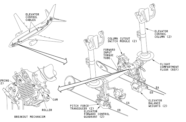
NG cockpit control system
See the little goodie named 'Breakout Mechanism'
That is there to restore controlability when something jams part of the flight control system. It's function is to separate the flight control system into two halves.With enough force differential between the two control columns, a cam system will disengage and allow the two sides of the control system to operate independently. From the FDR elevator force charts, the crew were applying force at the limits of their ability against the elevator feel system, and there is no sense in making a disconnect that requires more force than can be exerted. Just how far back in the aircraft would the system remain separated is the next question. It appears that the system would be separated back to the hydraulic power control unit input torque tube. The NG flight control system appears to have benefited from jammed flight control incidents involving earlier models. See this reference:NTSB Recommendation
My key takeaway is the following statement: "Further,the elevator system on 737-600 through -900 series
airplanes was improved by the addition of several mechanical override mechanisms. While these
override mechanisms do not mitigate all possible jam conditions, in general, in the event of a
system jam, the mechanisms allow both elevators to be controlled by the movement of the
unaffected control column."
However my reading on flight with jammed controls indicates that the crew should expect reduced control effectiveness. Whether or not flight with disconnected but not jammed pitch controls would experience decreased control effectiveness is dependent on the location and design of the additional override mechanisms required. What I suspect is that there are spring cartridges located both before and after the power control unit input torque tube.
Join Date: Jul 2009
Location: Not far from a big Lake
Age: 81
Posts: 1,454
Likes: 0
Received 0 Likes
on
0 Posts
Who needs a POGO?
Tucked into your control system pathways, you will also find a little gadget called a POGO. These give you the ability to maintain control although your flight control system is partially jammed. This item fits the category of "mechanical override systems" referred to in the previous posting. Rather than describe them myself, I figured that I would let a professional take that task. See Pogo Load Limiter
Now take a look at this simplified diagram of the elevator control on the 737NG (courtesy of Peter Lemme's Blog) Do you see the POGO?
Well, I said this is simplified. There has to be another set of Pogo-like mechanisms connecting the left and right control cables to the elevator input torque tube or else there would be no point to having the breakout mechanism discussed in my previous post.The two columns would be locked together through the elevator input torque tube. Consider the implications of what happens when the crew hauls back hard against the elevator feel and centering unit resistance!!
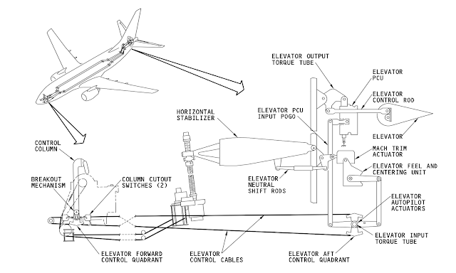
737-300 Elevator Control
Now take a look at this simplified diagram of the elevator control on the 737NG (courtesy of Peter Lemme's Blog) Do you see the POGO?
Well, I said this is simplified. There has to be another set of Pogo-like mechanisms connecting the left and right control cables to the elevator input torque tube or else there would be no point to having the breakout mechanism discussed in my previous post.The two columns would be locked together through the elevator input torque tube. Consider the implications of what happens when the crew hauls back hard against the elevator feel and centering unit resistance!!
737-300 Elevator Control
Last edited by Machinbird; 9th Dec 2018 at 15:47. Reason: update title of diagram with new information
Apparently, this bird ( 737) seems to act like most of us expected in the old days and even today until they let us fly a plane with negative or neutral static stability. We trimmed to reduce control pressure/movement. That got you back t the original AoA/speed. So you could have a lot of elevator deflection but the trim operation would allow less and less control pressure until you reached the desired trim for speed/AoA. And then we had STS, which trimmed the stabilizer without pilot input. Huh???? This ain't no Airbus fly by wire FLCS. But rational was to tell the pilot ( I use pilot to assert whoever was in charge of moving controls), he needed to trim for the new speed/AoA. What airplane have they flown that did not need a new trim after changin speed/AoA?? Do they need to be "reminded"? SHeesh.
And then we get another tweak to the plane's flight control system.. MCAS. And its operation and such are not well known by the rank-and-file aircrew. How much interplay between MCAS and STS and the articicial pitch "feel"?
And then we get another tweak to the plane's flight control system.. MCAS. And its operation and such are not well known by the rank-and-file aircrew. How much interplay between MCAS and STS and the articicial pitch "feel"?
The helicopter industry had just this occur with the introduction of the pitch bias actuator (PBA) on the S-76 and Blackhawk.
The FAA requires that you must have Longitudinal Static Stability (LSS), where the stick position for any speed must be ahead of a lesser speed. Without the PBA the helos demonstrated negative stick gradient in certain areas of the envelope, which certification said was a no, no. The PBA provides longitudinal cyclic displacement proportional to airspeed. The DAFCS commands the PBA as a function of pitch attitude, pitch rate, and airspeed. Failure modes were,
1. Attitude failure--bias actuator centered
2. Pitch rate failure--faded out pitch rate component
3. Airspeed failure--actuator goes to 120-knot position and attitude and rate continues to function
In practice pilots flying were unable to tell if the PBA was active or not, so the authorities were ultimately convinced that the PBA was not needed, and the system was removed from both the S-76 and Blackhawk. Negative Stick Gradient was a problem only for certification standards and did not impose a handling problem for the Pilot.

Salute Megan!
You can attribute my quotes, but I recognized it right away.
From megan
I feel that Megan has nailed it above, but it would be nice for us to see the pitch authority at various AoA and stick force gradient that seems to be a factor in certification. Many here are real aero folks and mostly pilots. We can handle it.
Being from the military "cert" community, I flew a few designs that would prolly have not been certified by the U.S. or other country aviation bureaus. I even flew one that failed several pitch and roll gradient specs, but USAF produce a few hundred and we flew the suckers because we had good checkouts and were briefed at length on the "waivers". I contrast this with the hapless crew on that Lion Air jet.
Added..... I flew one type that behaved just like all the aerodynamic classes said it should. Right up to about a degree or so of the critical AoA, and then whahooo!!! It was the VooDoo, so youse can look it up, but the real explantion is hard to find. The thing gave plenty warning when subsonic unless you yanked back real quick. But we had a "pusher" that used AoA and pitch rate and stick force to "help" us. However, the stick force per gee and rate and such was perfectly within the military certification requiremnts until that tiny degree of AoA before the pitch-up. And then any more back stick /AoA exhibited what we called the stick "getting light", and if you persisted, then you witnessed the wahoo, heh heh.
Glad we can discuss stuff here. Guess the casual folks on the main forum think they must be aero engineers of test pilots to be here.
Gums sends...
You can attribute my quotes, but I recognized it right away.
From megan
I wonder if the systems incorporated may prove to be installed to satisfy some certification clause, but not actually bringing any real benefit in the ability of the pilot to exercise control.
Being from the military "cert" community, I flew a few designs that would prolly have not been certified by the U.S. or other country aviation bureaus. I even flew one that failed several pitch and roll gradient specs, but USAF produce a few hundred and we flew the suckers because we had good checkouts and were briefed at length on the "waivers". I contrast this with the hapless crew on that Lion Air jet.
Added..... I flew one type that behaved just like all the aerodynamic classes said it should. Right up to about a degree or so of the critical AoA, and then whahooo!!! It was the VooDoo, so youse can look it up, but the real explantion is hard to find. The thing gave plenty warning when subsonic unless you yanked back real quick. But we had a "pusher" that used AoA and pitch rate and stick force to "help" us. However, the stick force per gee and rate and such was perfectly within the military certification requiremnts until that tiny degree of AoA before the pitch-up. And then any more back stick /AoA exhibited what we called the stick "getting light", and if you persisted, then you witnessed the wahoo, heh heh.
Glad we can discuss stuff here. Guess the casual folks on the main forum think they must be aero engineers of test pilots to be here.
Gums sends...
megan, gums, many of these points are also in thread B-737 Speed Trim System, post 81 onwards.
And additionally some other, as yet, unanswered thoughts on �collateral� effects, including those which �get into the trim system� per se.
And additionally some other, as yet, unanswered thoughts on �collateral� effects, including those which �get into the trim system� per se.
Salute PEI ,
Yeppers, I saw the great posts and such and learned a lot, but the other thread did not get into the MCAS for about 60 + posts. It is a really great discussion about stability and how the STS works and why.
Since the MCAS seems to be of major concern for the Lion accident, and because my strong feeling is we pilots should know about a significant change to our flight controls, I gravitated to this thread..
One thing that mabe FCeng can explain is the interaction between STS and MCAS. Seems to this old pilot that at certain flight conditions they are opposing each other. In other words if speed/AoA is changing, then one system is trimming opposite the other. Or am I way off base?
Gums asks...
Join Date: Sep 2016
Location: USA
Posts: 803
Likes: 0
Received 0 Likes
on
0 Posts
Salute PEI ,
One thing that mabe FCeng can explain is the interaction between STS and MCAS. Seems to this old pilot that at certain flight conditions they are opposing each other. In other words if speed/AoA is changing, then one system is trimming opposite the other. Or am I way off base?
One thing that mabe FCeng can explain is the interaction between STS and MCAS. Seems to this old pilot that at certain flight conditions they are opposing each other. In other words if speed/AoA is changing, then one system is trimming opposite the other. Or am I way off base?
Glad we can discuss stuff here. Guess the casual folks on the main forum think they must be aero engineers of test pilots to be here.