


A320 graduation markings behind thr lvrs

Thread Starter
Join Date: Mar 2008
Location: Chicago
Age: 52
Posts: 7
Likes: 0
Received 0 Likes
on
0 Posts
A320 graduation markings behind thr lvrs
This topic has probably been covered previously, I apologize in advance for repetition to those who have been through this before.
Can someone please give me the simple explanation of the purpose for these markings? Are they for pilots or mechanics?
Thanks!
Can someone please give me the simple explanation of the purpose for these markings? Are they for pilots or mechanics?
Thanks!

Join Date: May 2008
Location: Scotland
Age: 80
Posts: 451
Likes: 0
Received 0 Likes
on
0 Posts
Having never worked on A320, I can only comment that on aircraft I have worked with these graduations are used by maintenance to basically trim the engine to give an EPR or N1 figure commensurate with throttle position. With mechanical throttle systems on P&W engines for example a stop was inserted on the FCU,when the power lever in the cockpit was pushed fully forward to contact the stop, the lever was then adjusted to a given setting.The engine would then be run and adjusted to give the parameters required at that setting. I would imagine that with FBW systems it will be much the same but without the mechanical bit.
Thread Starter
Join Date: Mar 2008
Location: Chicago
Age: 52
Posts: 7
Likes: 0
Received 0 Likes
on
0 Posts
Thanks for offering answers even though my description is unclear. Can anyone tell me how to post a picture on this forum so you can see what I'm referring to? I'll take a picture when I fly this afternoon..
Join Date: Jul 2013
Location: Kansas
Age: 85
Posts: 63
Likes: 0
Received 0 Likes
on
0 Posts
Picture must stored on line, i.e Photobucket or the like.
When you are in the reply mode there is an icon (yellow looks like a mountain), clicking that it asks for the url for the location of the picture.
Kind of simple when you get used to it.
When you are in the reply mode there is an icon (yellow looks like a mountain), clicking that it asks for the url for the location of the picture.
Kind of simple when you get used to it.
Join Date: May 2008
Location: Scotland
Age: 80
Posts: 451
Likes: 0
Received 0 Likes
on
0 Posts
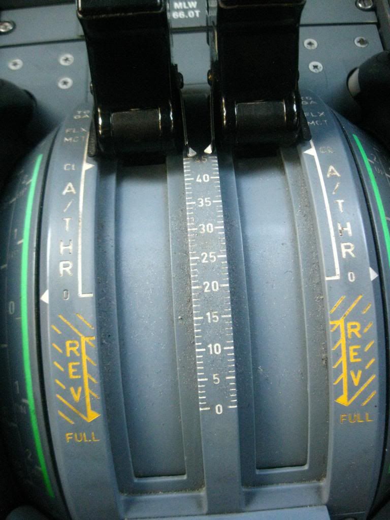
These are the degree markings that are used by maintenance for thrust lever rigging as I described in my previous post - I do not think they are used by aircrew for anything.

Join Date: Feb 2008
Location: 39.000 ft above the Earth
Posts: 12
Likes: 0
Received 0 Likes
on
0 Posts
It is the TLA
DSC-70-30-20
DSC-70-30-20
The thrust levers can only be moved manually.
They move over a sector that is divided into four operating segments.
The sector has five positions defined by detents or stops.
Thrust lever position is transmitted to the FADEC, which computes and displays the thrust rating limit and the N1 for that Thrust Lever Angle (TLA).
They move over a sector that is divided into four operating segments.
The sector has five positions defined by detents or stops.
Thrust lever position is transmitted to the FADEC, which computes and displays the thrust rating limit and the N1 for that Thrust Lever Angle (TLA).
