


What advantages does ac electrical power have over dc electrical power

Some good answers.
Just to reinforce what has mostly been said: AC generators are more efficient, more controllable, and capable of higher output currents without the disadvantages of the high current switching one gets with a DC generator, and the consequent sparking which could be hazardous. AC is easy to convert to different voltages with simple transformers. High power devices such as heated windscreens, fans, electric hydraulic pumps and prop blade heaters can use 'raw' AC directly.
Most avionics and electronic devices however, use DC voltages between 5 and 28 volts in their circuits. If supplied with AC, they therefore need to convert this to a lower DC voltage first, which would need a transformer and smoothing power supply circuitry in each device. Much easier to supply a suitable DC voltage to such devices. Large power convertors called Transformer Rectifier Units, TRUs, are used to produce 28VDC from the 115VAC.
28V is the same as an aircraft battery voltage, so if the TRU derived 28 volts fails, you still have 28V from the batteries to keep the essential systems alive to get you back on the ground. Also, some devices such as radios and navigation lights will work from batteries when on the ground with no engines running.
This is why most aircraft have both AC and DC distribution systems.
Last edited by Uplinker; 6th May 2013 at 00:40.

Join Date: Dec 2007
Location: Cyprus
Age: 91
Posts: 179
Likes: 0
Received 0 Likes
on
0 Posts
When aircraft started flying regularly at higher levels there were problems with heavy d.c. loads continuing to run after they were switched off; this was traced to arcs developing across the contacts of relays mounted in unpressurised areas. Using a.c. in which the voltage fell through zero many times a second alleviated this.
Join Date: Aug 2004
Location: Dallas, Tx
Posts: 16
Likes: 0
Received 0 Likes
on
0 Posts
Great thread going here, too bad I got onto to it a bit late.
Could one of you all explain how you can have two voltages from one generator, such as the 115/200 we find in many transport category aircraft?
I've never gotten a really good explanation that I can understand how it works, and how you can have both 115 and 200 VAC being run down the same bus with different implement drawing either 115 or 200 depending on their needs.
Thanks in advance!
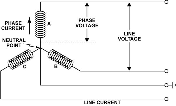
I'm pretty sure that refers to 3-phase power, where there's 200 volts between any two of the three legs and 115 volts between any leg and the neutral. The numbers don't add up (i.e. it's not 115/230 volts) because the legs are 120 degrees out of phase from each other, but each is in effect 180 degrees out of phase with the neutral.
That's the best I can explain it; I'm sure someone out there can do better.
That's the best I can explain it; I'm sure someone out there can do better.
Line voltage is root 3 of phase voltage.
IE. 115v x (approx) 1.72=200v.
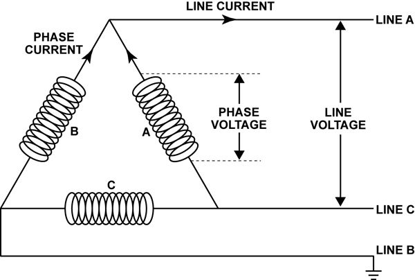
Depends if the generator is star or delta wound. One gives equal line and phase voltage the other gives equal line and phase current.
I think?
IE. 115v x (approx) 1.72=200v.
Depends if the generator is star or delta wound. One gives equal line and phase voltage the other gives equal line and phase current.
I think?

A 3 phase alternator has three coils arranged in a circle which produce voltages that are 120 degrees from each other.
The output of each coil is a sine wave - varying from zero volts to (in this case) 115 volts, then back to zero, then minus 115 volts then zero again.
Plot a graph with voltage on the vertical axis and degrees of rotation along the horizontal axis - I don't know how to draw that on here - the first coil's output begins at zero degrees and reaches 115V at 90 degrees then zero again at 180 degrees and so on. The second coil's output starts at 120 degrees along the horizontal axis and the third coil's at 240 degrees along.
Anyway, if you plot all this, you will see that the max voltage on any single coil is 115 V and the voltage between two coil's outputs can reach 200V. This is because when one coil is at 115V, another coil will be at -85V, so the difference is 200V
I hope you followed that! A diagram would be much easier to understand.
You cannot send different voltages down the same wire - even if you tried the result would always only be one voltage, but electrical devices will draw different currents from the same wire according to their needs.
Last edited by Uplinker; 4th Jul 2013 at 09:37.

Ah thanks guys - my limited IT ability prevented me doing that!
Hopefully this all now makes sense to CLDriver?
So the output of the alternator will be carried on 4 wires*; One for each coil (known as a 'phase'), and one connected to the neutral point which serves all three phases.
A piece of equipment needing low power 115V will connect between one phase and the neutral point. A piece of equipment needing high power will use all three 115V phases, each returning to neutral - feeding either three separate heating elements in a windshield or prop de-ice boot, or three separate coils in a hydraulic pump motor for example.
A piece of equipment needing 200V would connect between two of the phases and not neutral.
(*A delta system as shown in Lightning's second diagram above is configured differently and uses only 3 wires, but the principle is similar).
Last edited by Uplinker; 4th Jul 2013 at 11:16.
Join Date: Aug 2004
Location: Dallas, Tx
Posts: 16
Likes: 0
Received 0 Likes
on
0 Posts
Wow, this a completely awesome and very understandable way of explaining it. Thanks everyone!
We have 115/200 vac 400hz on the Challenger and everything on the AC buses run on 115, except, the windshield heats which are 200.
So if I understand correctly, even though the only thing on the Main Buses that operate on 200 is the Windshield Heat, everything else being 115, it is how the equipment running on the Main Bus connects to the phases depending on what it needs.
I scanned a pic of the windshield heat electrical diagram, but it wouldn't post, I hope I described it well enough.
This was always a fuzzy subject and over the years I try and take those areas and learn more about them. Thanks again all who have contributed!
We have 115/200 vac 400hz on the Challenger and everything on the AC buses run on 115, except, the windshield heats which are 200.
A piece of equipment needing low power 115V will connect between one phase and the neutral point.
A piece of equipment needing 200V would connect between two of the phases and not neutral.
A piece of equipment needing 200V would connect between two of the phases and not neutral.
I scanned a pic of the windshield heat electrical diagram, but it wouldn't post, I hope I described it well enough.
This was always a fuzzy subject and over the years I try and take those areas and learn more about them. Thanks again all who have contributed!
Last edited by CLDriver; 4th Jul 2013 at 19:02.
I am flying blind here in the absence of a circuit diagram for your particular situation, but as I say if a piece of equipment needs 200V, it will probably be connected across two of the three phases, instead of one phase and neutral.
For those who might not understand voltage and current:
Think of a hosepipe connected to the outside tap, with a trigger operated sprayer on the end. When you turn on the outside tap, the water pressurizes the hose, but no water flows because the sprayer end has not been switched on. The water pressure inside the hose is like the voltage in a cable. There is energy there, but nothing happens until you open the sprayer end (or draw current). When you pull the trigger on the sprayer end, water flows out. The flow of water is analogous to the current flowing through a wire. You could open the sprayer a tiny bit and a dribble of water would flow, or you could open it right up and maximum water would flow.
This is like different equipment drawing different current - a power hungry item such as a heater or a motor would draw a lot of current, but a light bulb would draw a tiny amount of current. With electrics, power is voltage times current = watts. So a piece of equipment using 10 amps from a 115V supply is using 1,115 watts, or 1.115KW of power. (To be precise; with an AC voltage it would be 1.115KVA, but don't worry about this distinction)
You could then imagine the hose having 'T' joints along it's length and different sized holes at each 'T' junction for the water to pour out. The pressure(voltage) in the hose is the same all along and at each junction, but a different amount of water flow(current) is drawn at each 'T' junction depending on the power requirement of the item.
One minor(ish) point - RMS
the first coil's output begins at zero degrees and reaches 115V at 90 degrees
There is one small point that I have not noticed mentioned so far.
I now cannot recall the details (but there for sure will be someone along in a minute who does) but the peak voltage is not 115.
The voltages quoted are as I recall so called Root Mean Square (RMS) values. I think that they are used because they make V=IR work for sinusoidal AC in exactly the same manner that it does for DC.
In the UK our single phase voltage (household) is 240 volts (ish - it may have been reduced a bit) and the three phase voltage (available for business use on request - never used domestically) is 440V. Both RMS. The peaks are much higher. (On recall, from decades ago, it might be square root of 2 times higher [1.41])
That's a good point. It isn't really necessary to explaining three-phase power, which is complicated enough already. But it probably is relevant to the earlier safety discussion. All other things (e.g. load and current) being the same, an AC system will involve voltage that spikes higher than a DC system, probably adding to the arc and shock hazard.
To add one more thing about three power: It isn't really about getting two voltages from a single system. You can do that with a "single" phase system that uses two hot conductors 180 degrees out of phase and a neutral at ground potential. The 120/240 residential power common in the United States works that way.
Where three-phase really earns its keep is in powering induction motors. Three coils spaced around the motor frame create a rotating magnetic field that starts the motor without the need for capacitors or other efficiency-reducing tricks. There may be advantages on the generation side as well, but I'm not as sure about that.
The voltages quoted are as I recall so called Root Mean Square (RMS) values. I think that they are used because they make V=IR work for sinusoidal AC in exactly the same manner that it does for DC.
In the UK our single phase voltage (household) is 240 volts (ish - it may have been reduced a bit) and the three phase voltage (available for business use on request - never used domestically) is 440V.
V L-L = sqrt(3) * V L-N
V L-L = sqrt(3) * 240 = 416
Three phase systems are typically identified by their line to line voltage.
Confusing enough for you?


The other big advantage with AC, of course, is that any ac voltage may be obtained via a transformer, and any DC voltage via a transformer/rectifier unit (TRU).
Yep, as already stated: check out post #21 
As for root mean square, RMS; yes, all true, but don't worry about it too much because it is not required to improve your understanding of the basic 3 phase system. Designers need to know because they need to know the highest voltages in the system, in order to correctly specify wire insulation, and they need to be able to compute the power and heating effects in the cables too.
As for root mean square, RMS; yes, all true, but don't worry about it too much because it is not required to improve your understanding of the basic 3 phase system. Designers need to know because they need to know the highest voltages in the system, in order to correctly specify wire insulation, and they need to be able to compute the power and heating effects in the cables too.
Last edited by Uplinker; 5th Jul 2013 at 08:53.
RMS value of AC is equal to the power dissipated by the equivalent value of DC.