


787 Batteries and Chargers - Part 1

Join Date: Aug 2011
Location: Grassy Valley
Posts: 2,074
Likes: 0
Received 0 Likes
on
0 Posts
saptzae,
Inadequate management at the internal short stratum? Primary? It must be prevented, not managed, to wit:
Management at the secondary level, post internal short, is not management, it is shutdown.
Management can not rectify the problems we see.
Internal short, leading to shutdown, takes a safety critical system "offline".
Internal short or any failure leading to FIRE, is disqualifying of the Battery's installation, let alone management......
The "FIREBOX" may work, but it is extraneous, the battery cannot be aboard, if there is even possibility of FIRE, by rule.
Do you see this?
Rather, by what we see, all boils down to inadequate management, on all levels.
Primarily, of the cells, so they short.
Secondarily, of the cell short, leading to the conflagration
That 100+ batteries got line replaced
Primarily, of the cells, so they short.
Secondarily, of the cell short, leading to the conflagration
That 100+ batteries got line replaced
Management at the secondary level, post internal short, is not management, it is shutdown.
Management can not rectify the problems we see.
Internal short, leading to shutdown, takes a safety critical system "offline".
Internal short or any failure leading to FIRE, is disqualifying of the Battery's installation, let alone management......
The "FIREBOX" may work, but it is extraneous, the battery cannot be aboard, if there is even possibility of FIRE, by rule.
Do you see this?
Last edited by Lyman; 10th Mar 2013 at 19:33.

Join Date: Aug 2011
Location: Grassy Valley
Posts: 2,074
Likes: 0
Received 0 Likes
on
0 Posts
A Nail is better than....What?
A nail is not representative of a typical FAIL. Overuse, over demand, age, Pressure/Temp cycling, vibration, etc.
A Nail is a parlor joke, right? A sledgehammer would not be appropriate either....
Again, no industry standards prior to July, 2011

A nail is not representative of a typical FAIL. Overuse, over demand, age, Pressure/Temp cycling, vibration, etc.
A Nail is a parlor joke, right? A sledgehammer would not be appropriate either....
Again, no industry standards prior to July, 2011
Join Date: Aug 2011
Location: hong kong
Age: 63
Posts: 93
Likes: 0
Received 0 Likes
on
0 Posts
@Lyman
I apologize for explaining things poorly. You help me to manage my posts better. Thank you.
By "Management" I refer to action it takes, to meet the objective of reliable and safe operation, irrespective on what takes the action.
I apologize for explaining things poorly. You help me to manage my posts better. Thank you.
By "Management" I refer to action it takes, to meet the objective of reliable and safe operation, irrespective on what takes the action.
Rather, by what we see, all boils down to inadequate management, on all levels.
- Primarily, of the cells, so they short. BMS fault
- Management of cells includes control, monitoring and balancing to assure reliable and safe operation.
- Control of battery charging
- Monitoring of cell voltages and battery current and temperature
- Real time determination of battery status and cell condition
- Battery voltage
- Battery current
- Battery temperature
- Cell voltage
- Cell voltage transients at individual cells. This is needed for cell short detection.
- As discussed earlier, cell pressure would be an interesting alternate way to detect cell shorts. This is optional.
- Balancing of cells by discharging cells at or above 4.025V
- Secondarily, of the cell short, leading to the conflagration BMS fault
- To prevent cascading failure after a cell short
- Disconnect battery
- Prevent charging .
- Prevent current flow into cells
- To prevent cascading failure after a cell short
- Apparently, at TAK, connections were found between APU and Main batteries (via Nav lights), which were not part of the design. Production QC fault?
- That 100+ batteries got line replaced Inaction?
- Problem persisted after a year in service until the grounding
A Nail is better than....What?
- A short by a nail is a bad test
- It is not realistic
- The short circuit resistance will be lower than a genuine cell short
- It is not realistic
- A good test would be representative of the smallest internal short, which could lead to damage to cell.
Join Date: Aug 2011
Location: Grassy Valley
Posts: 2,074
Likes: 0
Received 0 Likes
on
0 Posts
Thank you saptzae, for your patience with a layman.
I still am not tracking as to how a primary cause, an internal short, can be "managed".....
I was confusing management with "mitigation", so your response above helps in that regard. If you mean a well managed program, I see that as very helpful....
I found this interesting item in the Exponent paper...
One immediate question re: the "Materials Addendum"........
They found spherical globules of Stainless Steel in the Combusted products within the identified cell, number 6. That means 2700 degrees, and most of Exponents' text refer to 1100 degrees as typical in thermal runaway.....
What source of the metallic Stainless? Typical of cell container is Aluminum, as the enclosure represents.....A technician is holding what appears to be a damaged encasement (cell), could that be Stainless?
Have you any comment on the CT images of the exemplar cells' sections?
To me, the electrode stack is in disarray?
I still am not tracking as to how a primary cause, an internal short, can be "managed".....
I was confusing management with "mitigation", so your response above helps in that regard. If you mean a well managed program, I see that as very helpful....
I found this interesting item in the Exponent paper...
This fact has led to a misconception that lithium-ion cells burn vigorously because they �produce their own oxygen.� This idea is incorrect. No significant amount of oxygen is found in cell vent gases.91 Any internal production of oxygen will affect cell internal reactivity,11 cell internal temperature, and cell case temperature, but plays no measurable role in the flammability of vent gases
They found spherical globules of Stainless Steel in the Combusted products within the identified cell, number 6. That means 2700 degrees, and most of Exponents' text refer to 1100 degrees as typical in thermal runaway.....
What source of the metallic Stainless? Typical of cell container is Aluminum, as the enclosure represents.....A technician is holding what appears to be a damaged encasement (cell), could that be Stainless?
Have you any comment on the CT images of the exemplar cells' sections?
To me, the electrode stack is in disarray?
Not a good idea to enclose all the protective & contol circuits & components
in an area of a battery case which has known potential fire & heat issues as
well.
in an area of a battery case which has known potential fire & heat issues as
well.
just as soon as pics of the enclosure became available
 .
.
Could someone who has watched the current levels of the B787 APU battery
indicate that 45Amps without reducing for 15 mins after starting the APU
is a normal expected level as it seems a bit high.
indicate that 45Amps without reducing for 15 mins after starting the APU
is a normal expected level as it seems a bit high.
1) Apu startup, very high peak current demand, which significantly warms up
the cells
2) Immediate 45 amp charge current, which warms up the cells even more, with
one or more exceeding data sheet limits. The single thermal sensor doesn't see
this in time to shut down the charger, due to thermal resistance and lag across
the package. If it does see it, it's late, and the out of limit conditions
persist for long enough to cause some permanent, though not initially fatal cell
damage.
3) Cell eventually gets tired of being abused, thermal runaway in a single cell,
cascading to others. Game over.
I think temperature is the key here. These events may have been waiting
to happen for some time, but ambient temperature and low battery cycles have
mitigated it up to now. As the cells age though, ie: more and more flights
and charge discharge cycles, their ability to withstand abuse will be degraded.
The fact that it didn't happen in flight, yet, could simply be that that the ambient
temp may have been much lower than that on the ground.
Just a theory, but seems quite feasible ?.
To add to the mix, we have no clue what the controller software is up to,
algorithms used, how various limits are decided against time and other factors
directly or indirectly influenced by the charger and/or the bmu software...
Join Date: Jul 2009
Location: Not far from a big Lake
Age: 81
Posts: 1,454
Likes: 0
Received 0 Likes
on
0 Posts
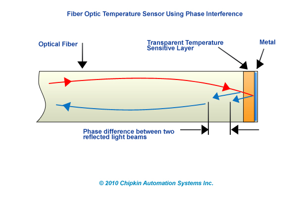
Battery temperature sensing
It is clear that battery temperature sensing was inadequate. To my mind, rather than an external temperature sensor, each cell needed an internal temperature sensor near its center of mass.
Rather than try to insert a thermistor type element with its conductive leads into this area of a battery, why not use a few strands of fiber optic glass down into the core of each battery cell.
The following pictures illustrate what is currently achievable.

Rather than try to insert a thermistor type element with its conductive leads into this area of a battery, why not use a few strands of fiber optic glass down into the core of each battery cell.
The following pictures illustrate what is currently achievable.
Join Date: Aug 2011
Location: hong kong
Age: 63
Posts: 93
Likes: 0
Received 0 Likes
on
0 Posts
@Lyman
A cell can be managed to not short. BTW, a cup of coffee can be managed to not spill or burn its contents consumer.
Link to exponent paper?
I have not read the materials report yet, it was hard to download. I will asap and get back.
Edit:
Browsed through materials and CT reports.
The cell case is stainless steel, stainless steel will be migrated inwards and deposited by arcing of internal parts to case.
The CT report shows cell bulging of main battery. This indicates that something is fundamentally wrong with battery management. This evidence of cell deterioration is a further step forward to figuring it out.
@syseng68k
Again, the BMU electronics in the same box is the better solution.
@syseng68k @whoever talked about 45A during 15 minutes
Please have a look at page 8 of recorders report 520291.pdf. The current of 40+A lasted only for 3-4 seconds
@Machinbird
3-4s of high current (45A) caused the conflagration! I estimate that BMS has less than 100ms to prevent electrically induced runaway after a cell short.
Thus am I afraid that temperature sensing will be too slow. Cell pressure sensing may be an interesting option.
Last edited by saptzae; 11th Mar 2013 at 11:02. Reason: Clarify
Join Date: Jul 2009
Location: Not far from a big Lake
Age: 81
Posts: 1,454
Likes: 0
Received 0 Likes
on
0 Posts
Originally Posted by saptzae
@Machinbird
3-4s of high current (45A) caused the conflagration! I estimate that BMS has less than 100ms to prevent electrically induced runaway after a cell short.
Thus am I afraid that temperature sensing will be too slow. Cell pressure sensing may be an interesting option.
3-4s of high current (45A) caused the conflagration! I estimate that BMS has less than 100ms to prevent electrically induced runaway after a cell short.
Thus am I afraid that temperature sensing will be too slow. Cell pressure sensing may be an interesting option.
Referring to the Boston battery failure,No one knows what temperature the cell that initially failed was at just prior to failure. The fact that the short appears to have occurred on the centerline of the plates is indicative of a temperature factor in the failure. If an overheated cell is detected early in the charge sequence (because the sensor is closely coupled to the cell), then current can be attenuated to that cell or the charge sequence aborted.
Once an actual failure begins to occur, then a pressure sensor or a rapidly responding current sensor can abort the charge and flag a battery malfunction, but that is after a failure. The main idea should be to never let the battery (as a whole and any portion of it) reach any of its limits.
My personal approach would be to charge the battery with a series of cell voltage chargers, each one floating at the potential of the actual cell it was charging.
Yes you would have more wires running into the battery, and you would have cell sensors running to the appropriate chargers, but there would be no need of a Battery monitoring unit in the battery itself. The chargers could record and control the status of each cell. If one cell required twice the time to accept a charge as its neighbor did while staying within temperature limits that fact could be accommodated and reported if appropriate.

Join Date: Feb 2011
Location: Nearby SBBR and SDAM
Posts: 875
Likes: 0
Received 0 Likes
on
0 Posts
Hi,
Mb @ #927
I fully agree with the concept of "parallel charging" you made implicit.
Actually i yet designed and yet using a prototype:
1) High current, through series config.
2) Low current, directly to each cell.
Good sugestions on ea. cell Temp and Pressure monitoring. Also agree should be considered in the redesign of 787 battery.
Join Date: Aug 2011
Location: hong kong
Age: 63
Posts: 93
Likes: 0
Received 0 Likes
on
0 Posts
The main battery at BOS shows cell deterioration, as per CT report.
The NTSB battery block diagram does not show cell balancing.
I was thinking that the block diagram is simplified. Perhaps block diagram is factual and battery has no cell balancing.
Without cell balancing, individual cell voltages can not be limited, and cell bulging and failure is to be expected.
Edit2:
If so, cell deterioration for lack of balancing, would be the long elusive cause of the Primary failure, the cell short.
Edit:
@Machinbird
General per cell temp monitoring will be of benefit to cell condition monitoring.
As to parallel charging. Just adds complexity at zero benefit, sorry.
@RR_NDB
Parallel low current discharge is whats needed to balance cells.
Last edited by saptzae; 11th Mar 2013 at 11:36. Reason: Edit
Join Date: Aug 2011
Location: Grassy Valley
Posts: 2,074
Likes: 0
Received 0 Likes
on
0 Posts
There are three cells in each of eight batteries.
Y'all are talking like each cell in each battery is not susceptible to this same imbalance failure, no? Each of the three cells is a unit made of differing quantities of "paste" applied to thin poly film.
Mechanical differences among these cells would seem to be the primary cause of failure. As small as one perforation or even ion by ion, the "Battery" is an accumulation of billions of cells, the electrode must collect and evenly distribute this energy to the connectors. Imbalance is the enemy, everywhere. Not just among eight gross boxes.
The failure is primary to a location on one of the three cells. Imbalance within the cell would seem to be the fault.
Moreover, each cell has millions of perforations on its separators, each one operating at a miniscule potential, and separate from all other perforations.
Balancing the batteries amongst themselves would NOT seem to be the answer.
This is a spontaneous failure. Spontaneous not meaning "Instantly".
Spontaneous as in "self creating". The charging exacerbates the failure it is not the genesis of the problem....
Conduction and resistance is causing the problem. Charging is just one of the roles of the system.
This battery is not happy with its work...
Copyrighted, found on the sidewalk....
http://www.nfpa.org/assets/files/pdf...rieshazard.pdf
Last edited by Lyman; 11th Mar 2013 at 14:20.
Join Date: Aug 2011
Location: Grassy Valley
Posts: 2,074
Likes: 0
Received 0 Likes
on
0 Posts
The use of copper as the current collector for the negative electrode has particular reliability and safety implications. At very low cell voltages (usually approximately 1 V for the cell), the potential at the copper current collector increases to the point where copper will begin to oxidize and dissolve as copper ions into the electrolyte. On subsequent recharge, the dissolved copper ions plate as copper metal onto negative electrode surfaces, reducing their permeability and making the cell susceptible to lithium plating and capacity loss. Usually, once a severe over- discharge event has occurred, cell degradation accelerates: once the negative electrode has become damaged by copper plating it will no longer be able to uptake lithium under �normal� charge rates. In such an instance, �normal� charge cycles cause lithium plating, which result in a greater loss of permeability of the surfaces. Ultimately, over-discharge of cells can lead to cell thermal runaway.
Out of my depth... But is this a precursor to the program of replacements? What would be the metric that alerts to the need to get the battery off the a/c ASAP?
Temperature logging? Inability to "take" a charge? What was the urgency in the replacement program? Reported is "over discharge". How many times and what was rhe evidence? What was the condition of the battery at removal? Any evidence of damage, potential hazards to continued presence onboard?
Certainly not "routine"......
Last edited by Lyman; 11th Mar 2013 at 14:11.
Join Date: Aug 2011
Location: hong kong
Age: 63
Posts: 93
Likes: 0
Received 0 Likes
on
0 Posts
@Lyman
I really do not understand your last two posts. All was discussed already.
No, there are 8 cells containing each 3 sub-cells, or elements in NTSB speak.
Not relevant. Cells are not to be discharged below 2.7V.
Why are you arguing against common engineering practice?
Why are we going in circles?
I really do not understand your last two posts. All was discussed already.
There are three cells in each of eight batteries.
Page 19
Why are you arguing against common engineering practice?
Why are we going in circles?
Join Date: Aug 2011
Location: Grassy Valley
Posts: 2,074
Likes: 0
Received 0 Likes
on
0 Posts
Howdy, thanks for responding.
Let me re-post what I think is important, and not at all argumentative (?)
Whatever the nomenclature, there are three wound cells in each of eight cases.
Any primary failure must have a point of origin. In the literature, one of these potential failures is at a perforation of the separator. It is one millimeter in diameter.
My take away from the discussion is that somehow, cell "balancing" (as to recharge) would solve the problem of runaway.
So my question: What locale is served by balancing? The electrode and collector must perform this on an instantaneous basis; any imbalance across the face of each electrode creates heat in addition to that of discharge/charge.
I see two issues. One, based on quality, is the potential for isolated and microscopic hot spots due to contamination and/or lack of care in assembly.
Two, the possibility of damage expressed as deformation of the electrode stack, this due to thermal and pressure cycling, and degradation of the paste(s), substrate, or separator elements.
Because that is what I hope for. I also believe that is what Boeing would hope for. Large format Lithium Ion Batteries might be the way of the future. If they are to be, Boeing is to be recognized for taking the step, FAA for allowing it, and the travelling public for placing trust in the system......
I do not think the charging issue or any other problem is related to this failure, except to say after the fact. Perhaps especially the default "CLOSED" contactors, which may have prevented takng the batteries off line....
NTSB: Single cell fault, No evidence of overcharge...(BTW, "overcharge" is not necessary, charging in and of itself produces heat, No?)
Take it away......
Join Date: Feb 2013
Location: Placerville, CA
Posts: 71
Likes: 0
Received 0 Likes
on
0 Posts
Lyman:
It is quite possible for there to be very localized heating at the ends of a high current arc without the entire surrounding area being at the same temperature.
The predicted temperature resulting from a thermal runaway is based entirely on the exothermic reactions at the anode and cathode and do not take into account either external power input or electrical heating resulting from internal or external short circuits that may occur during the process.
Is it reasonable to model the effects of two individually improbable simultaneous failure mechanisms (thermal runaway and short circuit)? Absolutely given that either one could induce the other!
Some comments were made about the inability of a single current sensor to detect a cell to case short circuit. In the Boston case at least, there is no evidence to suggest that the primary failure was a cell to case short circuit. Instead it appears to have been an internal short circuit of one cell.
In that case the + and - lead current of the series string would still be identical and the overvoltage applied to the non-shorted cells would affect cells on either side of the failed cell.
In the Narita case, the public information is not as clear as to just when in the sequence the cell to case short circuit took place.
Regarding the apparent damage to the electrodes of the main battery, I still feel that not enough attention has been publicly directed to the large amount (~10%) of volume expansion to be expected for the entire electrode stack between low voltage cutoff and high voltage cutoff charge levels. This is simply the result of chemical changes to the active material at the electrolyte surface and is in addition to any thermal expansion or contraction. The described problems leading to repeated over-discharge during ground operations has probably led to a greatly increased amount of cycling expansion and contraction compared to the predicted service life profile. Any additional complications from charge control anomalies and thermal expansion/contraction would only add to that.
They found spherical globules of Stainless Steel in the Combusted products within the identified cell, number 6. That means 2700 degrees, and most of Exponents' text refer to 1100 degrees as typical in thermal runaway.....
The predicted temperature resulting from a thermal runaway is based entirely on the exothermic reactions at the anode and cathode and do not take into account either external power input or electrical heating resulting from internal or external short circuits that may occur during the process.
Is it reasonable to model the effects of two individually improbable simultaneous failure mechanisms (thermal runaway and short circuit)? Absolutely given that either one could induce the other!
Some comments were made about the inability of a single current sensor to detect a cell to case short circuit. In the Boston case at least, there is no evidence to suggest that the primary failure was a cell to case short circuit. Instead it appears to have been an internal short circuit of one cell.
In that case the + and - lead current of the series string would still be identical and the overvoltage applied to the non-shorted cells would affect cells on either side of the failed cell.
In the Narita case, the public information is not as clear as to just when in the sequence the cell to case short circuit took place.
Regarding the apparent damage to the electrodes of the main battery, I still feel that not enough attention has been publicly directed to the large amount (~10%) of volume expansion to be expected for the entire electrode stack between low voltage cutoff and high voltage cutoff charge levels. This is simply the result of chemical changes to the active material at the electrolyte surface and is in addition to any thermal expansion or contraction. The described problems leading to repeated over-discharge during ground operations has probably led to a greatly increased amount of cycling expansion and contraction compared to the predicted service life profile. Any additional complications from charge control anomalies and thermal expansion/contraction would only add to that.
Join Date: Aug 2011
Location: Grassy Valley
Posts: 2,074
Likes: 0
Received 0 Likes
on
0 Posts
The LaminateLiner
inetdog
I think it would be instructive to look at the construction of each cell. Two metallic foil layers, two "paste" layers, and one "Separator", of polypropylene/polyethylene... Laid up flat, on a bench, no problem. But then it is required to "roll" this strip into a rectangular shape. What is the composition of the binders for each paste? One for Graphite, the other for LithiumCobalt Oxide?
How do these layers react to the stress of assembly?
More importantly, and given the telling photography of the MAIN Battery stacks, how does this laminated stack perform in service?
If the MAIN Battery (the "Exemplar"), shows such obvious signs of deformation, are we seeing the prelude to failure?
Poly is NOT resistant to heat, the perforations can shut, and the output can become disoriented to the electrode. That the Stainless enclosure is deformed is instructive of the stresses involved?
It is not a stretch to go here, NTSB made suggestive statements as to this avenue of the investigation, early on....
The described problems leading to repeated over-discharge during ground operations has probably led to a greatly increased amount of cycling expansion and contraction compared to the predicted service life profile. Any additional complications from charge control anomalies and thermal expansion/contraction would only add to that.
How do these layers react to the stress of assembly?
More importantly, and given the telling photography of the MAIN Battery stacks, how does this laminated stack perform in service?
If the MAIN Battery (the "Exemplar"), shows such obvious signs of deformation, are we seeing the prelude to failure?
Poly is NOT resistant to heat, the perforations can shut, and the output can become disoriented to the electrode. That the Stainless enclosure is deformed is instructive of the stresses involved?
It is not a stretch to go here, NTSB made suggestive statements as to this avenue of the investigation, early on....
Lyman.
I take your point about stresses at the folds and the quality control required to construct a device that works as advertised.
However, as single units these batteries (cells) appear to work well in other environments.
My understanding from previous posts, is that these battery 'cells' have been used extensively as individual units for many years without too many problems.
Bearing that in mind, I don't see how the construction of these individual 'batteries' can be at fault. It must be either the way they (all eight of them) interact as a group, whether that be thermally, electrically or physically, or there is a problem with the way they are being used (charged/discharged). Or indeed a combination of all these.
Its interesting to speculate about the battery failure modes and possible design improvements. But what is the service experience with the GS Yuasa LVP65 battery in other applications? Good? Bad?
If it is good, what is Boeing/Thales doing that other users are not?
In the final analysis, any technology will fail (spectacularly or otherwise) if pushed beyond its limits. If Boeing can't identify the particular conditions that exacerbate the failures, how can they be trusted to certify another design?
Join Date: Mar 2011
Location: engineer at large
Posts: 1,409
Likes: 0
Received 0 Likes
on
0 Posts
low voltage/high amperage arc...
thats easy...an arc welder
(another reason why when it gets going, it is difficult to stop)
thats easy...an arc welder
(another reason why when it gets going, it is difficult to stop)
Last edited by FlightPathOBN; 11th Mar 2013 at 17:10.