


Recording intercom and radio transmissions

Thread Starter
Joined: Jan 2008
Posts: 65
Likes: 0
From: Norway
A little update and a question. It turns out I have to order the attenuator since it doesn't seem to be available in any stores where I currently live. This is going to take some time (still haven't received the pick-up I ordered), and I was hoping to have something together by Tuesday. Therefor as someone suggested I got hold of a potensiometer and a regular mini jack cable and I was hoping to fashion out a variable resistor.

My question is about the brazing. The pot has three terminals and I've sliced the Right cable and connected the input to terminal 2 and the output to terminal 1, leaving the ground cable intact.
Have I done this correctly? So far I've only been able to test it with my Ipod and I can now control the volume with the pot.

Joined: Aug 2005
Posts: 1,693
Likes: 0
From: fairly close to the colonial capitol
Am I to understand the ground wire is unconnected to the pot Icenor?
If this is true, you have succeeded in introducing a resistance in the signal path, but technically not an attenuator. This may be sufficient but the chances are good that it will not be for your camera input.
To act as an attenuator lug #1 should be the input (from the audio panel) #2 the output (to the camera mic input) and #3 then the ground.
good luck!
edit: this illustrates the concept. The battery, on the left represents the output of your audio panel while the V (voltmeter) on the right is the intended camera input.
Last edited by vapilot2004; 2nd May 2010 at 23:35. Reason: clarity
Thread Starter
Joined: Jan 2008
Posts: 65
Likes: 0
From: Norway
Ok I just finished the pot and I belive it's now wired the way you described. I also build it inside a box so it wouldn't break that easily.

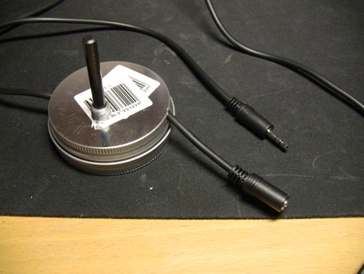
From the right side comes the input (audio panel) and out the left side goes the output (camera). The red wire is right-side audio in the stereo cable and the yellow is the ground.
Would it be possible for me to wire the left-side audio cable (white) to the right-side audio on the output side? That way the camera would record in stereo (it would still be from a mono source of course) and I wouldn't have to fix it in editing.
I also got the pick-up and I'll be testing both during a long flight tomorrow. I'll post the results for others to reference.
Thread Starter
Joined: Jan 2008
Posts: 65
Likes: 0
From: Norway
Nice work. Curious as to the source of the tin.

Heres the result from the telephone pick-up which was a great success. The first 25 seconds of the clip you hear exactly how it sounds when recorded on the camera. After 25 seconds I put the audio through some small editing to create stereo and I tried to remove that high pitch tone.
http://luftfartsfag.no/example3.wma
But when it came to the potentiometer, it wasn't as simple. It was hard to find the right setting because it wasn't possible to listen to the recording while in the aircraft due to the noise. I thought I'd found it by looking at the readings on my camera but you can hear what I ended up with here:
http://luftfartsfag.no/example4.wma
I'm guessing the low volume is a result of me setting to much resistance in the pot, and I just need to find the sweet spot between having to much or to little.


Fleet Manager

Joined: Apr 2001
Aviation Qualifications: ATPL
Posts: 7,448
Likes: 310
From: various places .....
It was hard to find the right setting because it wasn't possible to listen to the recording while in the aircraft due to the noise
Going back to what we use to do -
(a) always set up in the aircraft with things running using an earphone from the camera
(b) interestingly (and I have no idea why, being a greaser rather than queer trades fellow) for a given installation there was one pot setting which worked noticeably well
(c) you may have to try several resistance values to get a satisfactory result.
(d) I doubt that I have any archive audio but it certainly worked fine
Joined: May 2011
Posts: 1
Likes: 0
From: WPB Florida
I just made a simple cable that goes in line with the audio jack of my head set (or just plugged into an open audio plug of your intercom) and it works very well with a Drift HD recorder I am using to record aerobatic work. The circuit is VERY simple and consists of a 10K Ohm resistor tied to the audio source (tip of male audio plug) then a 10 microfarad ceramic capacitor in series with the other leg of the capacitor run to the mic input. The mic is then effectively capacitively coupled to your audio source which isolates the two circuits (protecting both). There is also a 10K source/load impediance (the 10K resistor) which limits any higher frquency current (again, protecting both devices).
so.... tip of male audio jack to one side of 10K 1/8th watt resistor.
other side of resistor to one side (either) of non-polarized 10 uF ceramic capacitor (5 to 25 or higher volts.... not critical)
other side of capacitor to mic level input of your recorder
so.... tip of male audio jack to one side of 10K 1/8th watt resistor.
other side of resistor to one side (either) of non-polarized 10 uF ceramic capacitor (5 to 25 or higher volts.... not critical)
other side of capacitor to mic level input of your recorder
Joined: Jul 2011
Posts: 2
Likes: 0
From: Sweden
I just made a simple cable that goes in line with the audio jack of my head set (or just plugged into an open audio plug of your intercom) and it works very well with a Drift HD recorder I am using to record aerobatic work. The circuit is VERY simple and consists of a 10K Ohm resistor tied to the audio source (tip of male audio plug) then a 10 microfarad ceramic capacitor in series with the other leg of the capacitor run to the mic input. The mic is then effectively capacitively coupled to your audio source which isolates the two circuits (protecting both). There is also a 10K source/load impediance (the 10K resistor) which limits any higher frquency current (again, protecting both devices).
so.... tip of male audio jack to one side of 10K 1/8th watt resistor.
other side of resistor to one side (either) of non-polarized 10 uF ceramic capacitor (5 to 25 or higher volts.... not critical)
other side of capacitor to mic level input of your recorder
so.... tip of male audio jack to one side of 10K 1/8th watt resistor.
other side of resistor to one side (either) of non-polarized 10 uF ceramic capacitor (5 to 25 or higher volts.... not critical)
other side of capacitor to mic level input of your recorder
1 question though.. Is the audio source and mic input grounded together?
// Space

Joined: Oct 2010
Posts: 422
Likes: 5
From: 5� above the Equator, 75� left of Greenwich
I'm planning to make videos of my flights as well. I've found two cables that might work.
XCOM STEREO <br>VIDEO PATCH CABLE from Aircraft Spruce
AIRCRAFT INTERCOM RECORDING CABLE from Aircraft Spruce
Could anyone give me an opinion about these two?
Thanks in advance
XCOM STEREO <br>VIDEO PATCH CABLE from Aircraft Spruce
AIRCRAFT INTERCOM RECORDING CABLE from Aircraft Spruce
Could anyone give me an opinion about these two?
Thanks in advance
