


B747 & B707 Pointy things.

Thread Starter
Joined: Jul 2009
Posts: 62
Likes: 0
From: In a hotel (again)
B747 & B707 Pointy things.
Hi got a question about some of the older model B747 aircraft pre 400 model ie before winglets. On these older model 747s at the wing tips on the trailing edge there are long pointy things sticking out what are they?
Also on the B707 at the top of the tail there is also a long pointy thing it facing forwards looks somewhat like a pitot tude what are these ?
Sorry for my technical jargon about the pointy things just curiosity really.
Also on the B707 at the top of the tail there is also a long pointy thing it facing forwards looks somewhat like a pitot tude what are these ?
Sorry for my technical jargon about the pointy things just curiosity really.

Joined: Aug 2007
Posts: 118
Likes: 0
From: Seattle KBFI
pre-400 or "Classic" 747-100/200/300 has the High Freq (HF) antenna extending aft from the wingtip. On the -400, they are enclosed in the leading edge of the tailfin or vert stab.
I believe it IS the pitot tube on the 707/720, that looks like a pitot tube on the tail.
I believe it IS the pitot tube on the 707/720, that looks like a pitot tube on the tail.

Joined: Oct 2005
Posts: 3,218
Likes: 2
From: USA
What you see there is actually just the tip of the antenna, too. The tuner includes the majority of the antenna, and it's a long metal tape (I forget how long, but long) wound up on a drum inside the wingtip).
If you have a model of the 747, the HF antennas are usually the first part to break.
If you have a model of the 747, the HF antennas are usually the first part to break.

Joined: Jul 1999
Posts: 3,040
Likes: 0
From: 58-33N. 00-18W. Peterborough UK
.... it's a long metal tape (I forget how long, but long) wound up on a drum inside the wingtip).

Joined: Jul 1999
Posts: 3,040
Likes: 0
From: 58-33N. 00-18W. Peterborough UK
Calm down you lot! Guppy's comment 'The tuner includes the majority of the antenna, and it's a long metal tape (I forget how long, but long) wound up on a drum inside the wingtip)' should have appeared in quotes. Ask the server why it wasn't. Anyway, we were talking 707 747 here and there is no ' long metal tape (I forget how long, but long) wound up on a drum inside the wingtip'
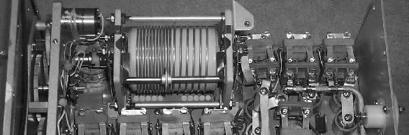
See here .... the inside of a coupler with the 'longest' bit shown. ( I still think Guppy was talking trailing aerials.)
See here .... the inside of a coupler with the 'longest' bit shown. ( I still think Guppy was talking trailing aerials.)
Joined: Oct 2005
Posts: 3,218
Likes: 2
From: USA
I thought for a moment you were talking about trailing antennas.You weren't ....... were you?
Certain HF antenna tuners can have a couple hundred feet of tape in them, internal to a drum, and this is true in the 747 Classic.
Joined: Nov 2006
Posts: 896
Likes: 2
From: SoCalif
The 707, 727 and 747 use the same basic concept probe (high voltage) antenna. It's at the top of the fin pointed forward in the 707; pointed aft in the 727. The 707 and 727 use the Collins 180R-12 antenna coupler, similar inside to above, and the 747 uses the 180R-17, which is just the same only different.
Some couplers have a beryllium copper tape about 0.5 cm wide, but I can't remember which ones. I'm pretty sure the 180R-17 uses the variable inductor on a drum, as above.
If you've ever watched the wingtip of a 747 at work, you know what torture those electromechanical couplers have to endure. They are usually failed or ready for overhaul by 2,000 hours.
The retrofit leading edge (high current) antenna was developed by a Brit engineer at Douglas for the DC-10, concurrent with similar development on the L-1011, and availability of high current couplers. The notch (high current) antenna up the vertical was developed by Eastern Airlines for their 727 fleet, and sold widely. Boeing eventually adopted that one for their 727 and 737 production, and on into the 747-300. All current generation airliners use the same high current antenna and coupler concept.
GB
Thread Starter
Joined: Jul 2009
Posts: 62
Likes: 0
From: In a hotel (again)
Firstly thanks for all the replies
But I am now more confused than ever I now know that they are part of the HF antennas but I am totally confused about it so its just the start of a long antenna that is much bigger than which is actually visable on the outside? its the moving bit that confues me, what moves ?
Funnily enough it actually turned out to be quite relevent to me as I have been using HF recently and the HF is not working very well in my aeroplane ( light twin and I know that is how most things work on them especilly the avionics ) at first I thought it was just a bad HF but it receives really quite well but no one can seem to hear me, I was told if I speak into it quiety and really softley it will work as it is over modulating ( to be honest might as well be alien talk to me but I would like to know more ) but it has seemed to resolve the problem by a small margin what do you all think.
Off topic slightly from my origin post I know but probably still relevent.any info would be great.

Joined: Feb 2004
Posts: 1,410
Likes: 37
From: Australia
But I am now more confused than ever I now know that they are part of the HF antennas but I am totally confused about it so its just the start of a long antenna that is much bigger than which is actually visable on the outside? its the moving bit that confues me, what moves ?
There are sliding contacts on the wire coil inside the "tuner" or "coupler" as these boxes are usually called. These contacts "tap off" a section of coiled wire corresponding to the correct length required for best transmission.
I suppose there could be something wrong with your tuner. It's the part most likely to fail. By the way, what sort of antenna do you have? Is it strung between the fuselage and the tail?


Joined: Jul 2008
Posts: 1,146
Likes: 31
From: Skating away on the thin ice of a new day.
NSEU is right. The tuner presents the transceiver with a matched load ie 50 ohms where it is designed to operate efficiently.
In effect the tuner makes the antenna look like the right length for the frequency your are transmitting on.
In aircraft the antenna is generally very very short for the wavelength so the tuner has some work to do to make it "look" longer.
They are a compromise, a short inefficient antenna but it is aerodynamic.So they pump in hundreds of watts and tune the blazes out of it to make it work.
As for your over modulation.Sounds a bit odd , aero mics generally need to be close talked to work well so that they dont pick up all the cr@p from the motors etc. Maybe the gain is a little hi on your headset? You shouldnt need to talk really quietly to make yourself readable.
Can you try another headset / mic perhaps?
As for bits moving.It all happens inside the tuner / coupler .(another word same thing).Some have little motors driving coils slugs and capacitors to make the antenna look resonant.More modern ones switch/tune very quickly. The antenna is just a fixed length bit of leading edge/cavity or wire in your case on light aircraft.
Have a read about tuned circuits, antenna theory, and resonance.
Thread Starter
Joined: Jul 2009
Posts: 62
Likes: 0
From: In a hotel (again)
My antenna is hung between the tail and the fuselage, I have tried two headsets my self with it and about 3 or 4 other Pilots from my company have had the same problem as well, its been tested at least 4 times that I can remember but it bench tests ok apparently? They decided to replace it at one point but one guy flying it said it worked fine so they didnt.(Belive me it dont I say but one good report seems to be enough but 10 bad ones is not quite enough ! )
Anyway point is I really dont know much about the subject so Ill do a bit of reading.
Cheers pistinaround.
Anyway point is I really dont know much about the subject so Ill do a bit of reading.
Cheers pistinaround.
Joined: Jan 2005
Posts: 2,315
Likes: 10
From: France
As already mentioned above, some aircraft have "slot" or "notch" HF antennas in the vertical tail. Not overly efficient, HF-wise, but they have the advantage of not causing drag.
Usually they're painted over, so you can't see them, and it's difficult to imagine what they look like.
Here's an exception, the British Concorde prototype 002.

Concorde had two separate HF transmitter-receivers, hence the two separate notches (plastic-covered) in the forward part of the vertical tail..
History doesn't tell why on Concorde 002 they were not painted until shortly before the end of its career.... on all other Concordes they were painted over.
Us aficionados apreciate it.... it often makes it possible to identify 002 in a photo, even in the absence of other clues.
A closely related tale....
As already mentioned too, notch antennas are very low-impedance, hence very high HF currents are induced in the structure around it.
During early flight tests it was noted that whenever somebody talked on the HF...... Concorde slightly wagged its tail!
After having some long and hard looks at the flight test recordings, we traced it to the yaw rate gyros (mounted in the tail) of the autostab system. The HF currents in the area were such, that the gyros picked it up and produced a spurious yaw rate signal.
Once we'd found the source, some additional RFI filtering took care of the phenomenon.
CJ
Usually they're painted over, so you can't see them, and it's difficult to imagine what they look like.
Here's an exception, the British Concorde prototype 002.
Concorde had two separate HF transmitter-receivers, hence the two separate notches (plastic-covered) in the forward part of the vertical tail..
History doesn't tell why on Concorde 002 they were not painted until shortly before the end of its career.... on all other Concordes they were painted over.
Us aficionados apreciate it.... it often makes it possible to identify 002 in a photo, even in the absence of other clues.
A closely related tale....
As already mentioned too, notch antennas are very low-impedance, hence very high HF currents are induced in the structure around it.
During early flight tests it was noted that whenever somebody talked on the HF...... Concorde slightly wagged its tail!
After having some long and hard looks at the flight test recordings, we traced it to the yaw rate gyros (mounted in the tail) of the autostab system. The HF currents in the area were such, that the gyros picked it up and produced a spurious yaw rate signal.
Once we'd found the source, some additional RFI filtering took care of the phenomenon.
CJ
Joined: Nov 2006
Posts: 896
Likes: 2
From: SoCalif
Notch/slot antennas on commercial aircraft are single, fed by two transceivers and two tuners/couplers wired in parallel to that single antenna.
They are much more efficient, as they excite the entire airplane into an antenna, vs. just a probe. That's the reason so many 727 and some 747 were converted from probe to notch antennas, and why the DC10-11 have superior HF performance.
I don't understand all I know about it, but the 757/767 and other Boeing HF is often lacking. Boeing just hasn't understood and applied the principles, such as total resistance, which must be less than ten milli-ohms. I've had the good fortune to know Ben Hornby, ex-pat Brit at McDouglas, who was responsible for the DC-10 HF antenna, and some Brit plane before that, possibly the Trident.
There also must be as much structure as possible above the antenna, as in the DC-10, where the antenna is just below the number two engine, and the 727 with its T-tail. Other a/c aren't so well endowed for HF.
After the AA A300 accident, the awfully high currents involved set me to wondering about HF antennas in carbon fiber vertical fins, and possible long term deterioriation of the structure.
GB