


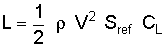
Lift Formula - IAS, CAS or EAS

Join Date: Jul 2006
Location: Earth
Age: 61
Posts: 66
Likes: 0
Received 0 Likes
on
0 Posts
TAS... see below...
where
lift force English:
slugs/ft3 Metric:
kg/m3
Air density
Air density changes as a function of altitude, so the value of this variable depends on the height you want to find the lift at. You can find tables of the air properties at different altitudes in the appendices of any elementary aerodynamics book, and you can also compute these properties at the Aerospaceweb.org Atmospheric Properties Calculator. All you need to do is enter the altitude you want and the script will compute the temperature, density, pressure, speed of sound, and other properties at that height. The other input values, like velocity and reference length, are not necessary unless you want to perform the rest of the calculations available.
Aircraft velocity
The form of velocity applicable to the lift equation is the true airspeed. True airspeed is defined as the actual speed of the aircraft through the air and includes corrections for density, compresibility, and instrumentation error.
Reference area
For an airplane, the reference area is the area of the wing when viewed from overhead. This can be somewhat confusing because it includes the area of the wing if it were extended through the fuselage: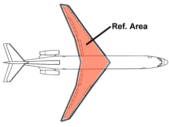
For a helicopter, reference area is the rotor disk area, or the area of the circle through which the rotor blades turn: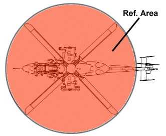
These values are provided for many aircraft at The Aircraft Museum. CL -
Coefficient of lift
This variable is a non-dimensional value that changes with speed as well as angle of attack and is dependent on the aircraft. Although CL is usually determined from wind tunnel experiments (or from computational methods that are beyond the scope of this question), the lift coefficient can be estimated fairly accurately for most aircraft. The following graph compares wind tunnel data for two actual aircraft. One set of is based on the Cessna 172, a low-speed plane with a single piston engine. The other set of data is for the BAC Lightning, a Mach 2 jet-powered British fighter with a wing sweep of 60�. Planforms of these aircraft are shown along with their lift coefficient results.
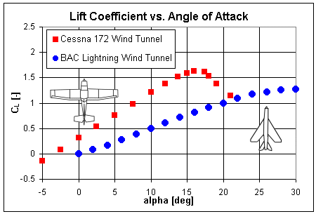
Most aircraft will be behave similarly to the Cessna 172 while high-speed planes with short wingspans, like fighters, will more closely resemble the Lightning data.
This answer came from - Jeff Scott, thus any credit of comment should directed to him. http://www.aerospaceweb.org/about/bios/jeffscott.shtml
where
lift force
English:slugs/ft3 Metric:
kg/m3
Air density
Air density changes as a function of altitude, so the value of this variable depends on the height you want to find the lift at. You can find tables of the air properties at different altitudes in the appendices of any elementary aerodynamics book, and you can also compute these properties at the Aerospaceweb.org Atmospheric Properties Calculator. All you need to do is enter the altitude you want and the script will compute the temperature, density, pressure, speed of sound, and other properties at that height. The other input values, like velocity and reference length, are not necessary unless you want to perform the rest of the calculations available.
Aircraft velocity
The form of velocity applicable to the lift equation is the true airspeed. True airspeed is defined as the actual speed of the aircraft through the air and includes corrections for density, compresibility, and instrumentation error.
Reference area
For an airplane, the reference area is the area of the wing when viewed from overhead. This can be somewhat confusing because it includes the area of the wing if it were extended through the fuselage:
For a helicopter, reference area is the rotor disk area, or the area of the circle through which the rotor blades turn:
These values are provided for many aircraft at The Aircraft Museum. CL -
Coefficient of lift
This variable is a non-dimensional value that changes with speed as well as angle of attack and is dependent on the aircraft. Although CL is usually determined from wind tunnel experiments (or from computational methods that are beyond the scope of this question), the lift coefficient can be estimated fairly accurately for most aircraft. The following graph compares wind tunnel data for two actual aircraft. One set of is based on the Cessna 172, a low-speed plane with a single piston engine. The other set of data is for the BAC Lightning, a Mach 2 jet-powered British fighter with a wing sweep of 60�. Planforms of these aircraft are shown along with their lift coefficient results.
Most aircraft will be behave similarly to the Cessna 172 while high-speed planes with short wingspans, like fighters, will more closely resemble the Lightning data.
This answer came from - Jeff Scott, thus any credit of comment should directed to him. http://www.aerospaceweb.org/about/bios/jeffscott.shtml

Join Date: Jun 2004
Location: Australia
Posts: 1,843
Likes: 0
Received 0 Likes
on
0 Posts
Now THAT was the complete answer to end all answers. 
 It's also TRUE, just like the V in the formula is TRUE.
Seeing as you mentioned EAS, EAS = TAS / SQR(Inverse Density Ratio), (mentioned because someone in the RAF once taught that the V was EAS).
As for IAS, forget it!
Regards,
Old Smokey
It's also TRUE, just like the V in the formula is TRUE.Seeing as you mentioned EAS, EAS = TAS / SQR(Inverse Density Ratio), (mentioned because someone in the RAF once taught that the V was EAS).
As for IAS, forget it!
Regards,
Old Smokey
Last edited by Old Smokey; 30th Jul 2006 at 15:11.
Join Date: May 2003
Posts: 409
Likes: 0
Received 0 Likes
on
0 Posts
Two quick questions that you gurus should be able to answer, if not quibble back and forth about:
1. If the slats/flaps are the type that move forward, and aft, of the wing, then does the wing reference area change? (When using the formula L = .5 * rho * V sq * Sref * Cl ) ? Or is the convention to keep the same Sref?
2. With respect to the graph of aoa VS Cl, what is the convention for measuring the aoa? For example 1, consider an aircraft straight and level without slat or flap, and at 5 degrees pitch. Now consider example 2, where the aircraft is slower, still straight and level, but now WITH slat and flap, and at the same 5 degrees pitch. Is the aoa the same for the two examples? After all, the chord angle is now entirely different once slat/flap are added. However, I'm wondering if the chord angle, by convention, is taken in the clean config, and not adjusted for high lift devices?
Hawk
Join Date: Sep 2002
Location: La Belle Province
Posts: 2,179
Likes: 0
Received 0 Likes
on
0 Posts
1. Same Sref. Bear in mind it's purely a reference area, you could use 1 sq ft (1 sq m) if you like; as long as you stay consistent it doesn't matter. Its not uncommon to leave Sref unchanged even if you actually change the wing area of a type, either in development or as a variant.
2. Alpha is generally measured against the fuselage reference line for a given type - changes to the local chordline are ignored. (Apart from anything else, most wings dont have the same chordline along the span - washout - and most flaps and slats only cover a portion of the wing, so it'd be almost impossible to define a single value for the whole wing.
2. Alpha is generally measured against the fuselage reference line for a given type - changes to the local chordline are ignored. (Apart from anything else, most wings dont have the same chordline along the span - washout - and most flaps and slats only cover a portion of the wing, so it'd be almost impossible to define a single value for the whole wing.
Join Date: May 2003
Posts: 409
Likes: 0
Received 0 Likes
on
0 Posts
MFS, thanks for your interesting input. If wing reference area can be so loosely defined, then I would expect that companies like Boeing and Airbus can then boast somewhat erroneously on the capabilities of their wings. For example, using a slat system that gives increased chord, and flaps that extend not only down, but back as well, actually is a new airfoil, with an increased area. To use the original reference area allows the manufacturer to therefore be able to claim their wing is able to attain a higher coefficient of lift than the true wing area would allow. Further, if the reference area may be left the same even when changes to the wing size take place, then adding an extra 10 feet to a wing can really skew the Cl values.
Is my logic invalid?
Re point 2, just to make sure I understand what you've written, is it correct to say then that an aircraft straight and level, with the 2 different configurations I gave in examples 1 and 2, and both at 5 degrees pitch, will therefore be considered to be at the same aoa?
Hawk
Is my logic invalid?
Re point 2, just to make sure I understand what you've written, is it correct to say then that an aircraft straight and level, with the 2 different configurations I gave in examples 1 and 2, and both at 5 degrees pitch, will therefore be considered to be at the same aoa?
Hawk
Join Date: Feb 2005
Location: flyover country USA
Age: 82
Posts: 4,579
Likes: 0
Received 0 Likes
on
0 Posts
Originally Posted by Mad (Flt) Scientist
...Its not uncommon to leave Sref unchanged even if you actually change the wing area of a type, either in development or as a variant...
I'm thinking of a light (well, MTOW=4100#) type originally certified in 1937 with A=185 sq.ft., excluding the projected area across the fuselage.
In 1940 a derivative type was certified with a widened fuselage, but identical chord, span, tip shape etc. But this time the area quoted was 210 sq.ft. including the projected area across the fuselage. This despite the fact the wing assemblies were slightly smaller!

Moderator
Some points being missed in the last posts ..
(a) S doesn't matter .. it's just a quantity necessary to make the units right in a non-dimensional parameter and is for OEM convenience .. at the end of the day CL is just a number and, as you have observed by inference, comparison of CL is not normally the mode of rating competing aircraft. Having said that, most OEM use similar (if not identical) definitions so notional comparisons are not unreasonable.
(b) the OEM sells aircraft based not on absolute CL values but hard dollar quantities which involve aerodynamic parameters .. eg take off and landing distances, fuel burn, econ speeds, etc. The customer out there in the marketplace really isn't too fussed about what CL values the OEM plays with ...
Join Date: Sep 2002
Location: La Belle Province
Posts: 2,179
Likes: 0
Received 0 Likes
on
0 Posts
Originally Posted by hawk37
Re point 2, just to make sure I understand what you've written, is it correct to say then that an aircraft straight and level, with the 2 different configurations I gave in examples 1 and 2, and both at 5 degrees pitch, will therefore be considered to be at the same aoa?
Now, if I'm doing detailed fluid-dynamics design work and endeavouring to, say, tailor the natural stall breakdown across the wing then consideration of local flow angles is important, but you have to really get into the weeds for that to matter, and nowadays it'd be done by 3d CFD, again using the aircraft-level AoA rather than worrying about the local conditions
To address J_T's points: yes, OEMs all use much the same definitions for Sref, so you can ROUGHLY compare CL-max across products. But I've been involved in some significant wing changes which added wing area where we chose not to change Sref (or the MAC definition) to keep data comparisons simple. Now, anyone marvelling at how we increased CLmax by 10% without spotting we had increased the area by 5% would be misled, but since as J_T also says no-one outside of the CFD bragging-rights wing design community gives two cents who has the "highest CL" it doesnt matter.
And if you think Sref is subject to a bit of creative accounting, just try to compare fin areas ....
