


Why are aircraft engines slightly tilted down?


Paging tdracer ...
But till he arrives, I am going to say that because aircraft typically cruise a few degrees nose-up, with the engine thrustline tilted downwards slightly on the ground, this places the engines thrust vector completely horizontal in the cruise thereby eliminating any 'wastage' of fuel that would otherwise be converted into in an unnecessary vertical component if they were indeed parallel to the waterline...
But till he arrives, I am going to say that because aircraft typically cruise a few degrees nose-up, with the engine thrustline tilted downwards slightly on the ground, this places the engines thrust vector completely horizontal in the cruise thereby eliminating any 'wastage' of fuel that would otherwise be converted into in an unnecessary vertical component if they were indeed parallel to the waterline...
There is upwash as the subsonic plane moves through the air because the air is being shoved forward. See Figure 4.3 in https://www.aircraftspruce.com/catalog/pdf/13-08723.pdf and
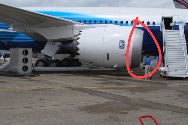
The majority of the explanations in that link are suspect as the engine core is clearly parallel to the fuselage. It is only the inlet that is tilted.
The majority of the explanations in that link are suspect as the engine core is clearly parallel to the fuselage. It is only the inlet that is tilted.

Aircraft body is tilt up a bit in level flight. In addition you compensate with the thrust vector downward, if the engines are forward of the CG that the engines below create a nose up force.
With props at the nose it is the same, they are tilted downward a bit too, to compensate for nose up in high throttle settings. In optimum you want a neutral reaction for different throttle settings.
With props at the nose it is the same, they are tilted downward a bit too, to compensate for nose up in high throttle settings. In optimum you want a neutral reaction for different throttle settings.
The inlet has a downward cant but I think the engine and exhaust are parallel to the waterline. Perhaps on the ground all that engine weight hanging from a beam ahead of the wing leading edge gives it a bit of a droop, the pods do dance about in turbulence, the wing too is a flexible structure.

Last edited by megan; 8th Nov 2023 at 06:00.
[QUOTE=ddanu9015;11535238]Hey Mates.. Have you noticed that aircraft engines are slightly tilted down ?
Why are aircraft engines slightly tilted down?
QUOTE]
That's only when viewed resting on flat ground. When viewed in flight they are correct. - thankfully some clever Aeronautical Engineers saw to that!
Why are aircraft engines slightly tilted down?
QUOTE]
That's only when viewed resting on flat ground. When viewed in flight they are correct. - thankfully some clever Aeronautical Engineers saw to that!

Tabs please !
Ann Hedral (Dai's sister) will be along shortly.
If the engines were mounted above the wings and thrust line then they would need to be tilted up. If they are in the thrust line like a Comet then neutral thrust line and if like most airliners when mounted below thrust line then down tilt needed as if they were not tilted there would be a big upward tilt on thrust being applied. Typed after lots of wine beer and sake so seems factually correct right now.
Because they are flexible cantilever beams and carrying the weight of the engines. When they generate lift, they "bend" straight. If the engines weren't there they'd bend upwards and would need to be much stronger cantilevers. The weight of the engines however gives them "bending relief".
The weight they have to carry is loaded along the length of the wing. If all the lift had to be transferred to the fuselage at the wing root, they'd have to be built like a brick outhouse. I image Comets, 1-11s, Tridents and VC10s had much stronger wings to resist bending than most Boeings.
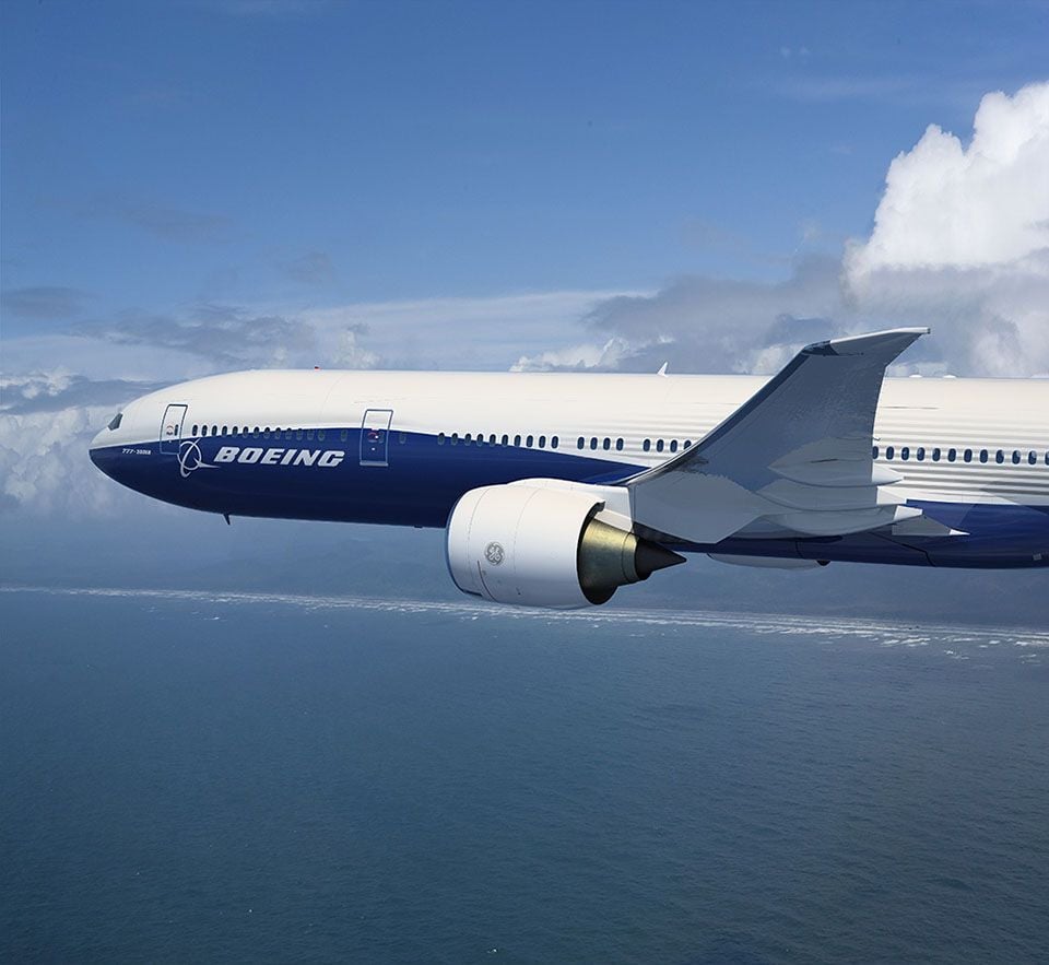
But look at the 787 which has a decided upward bend in flight.
The weight they have to carry is loaded along the length of the wing. If all the lift had to be transferred to the fuselage at the wing root, they'd have to be built like a brick outhouse. I image Comets, 1-11s, Tridents and VC10s had much stronger wings to resist bending than most Boeings.
But look at the 787 which has a decided upward bend in flight.
Last edited by Dave Gittins; 8th Nov 2023 at 12:26.
If the engines were mounted above the wings and thrust line then they would need to be tilted up. If they are in the thrust line like a Comet then neutral thrust line and if like most airliners when mounted below thrust line then down tilt needed as if they were not tilted there would be a big upward tilt on thrust being applied. Typed after lots of wine beer and sake so seems factually correct right now.
That's entirely separate from the thrust-line-in-the-cruise issue discussed above.
Join Date: Mar 2005
Location: UK
Posts: 551
Likes: 0
Received 0 Likes
on
0 Posts
I don't think it's really 'angled down' as such. It's just the bottom half of the intake is set further back than the top. This is so that at high angles of attack the lower lip doesn't shroud the oncoming air and disrupt it resulting in a possible compressor stall.
The inlet has a downward cant but I think the engine and exhaust are parallel to the waterline. Perhaps on the ground all that engine weight hanging from a beam ahead of the wing leading edge gives it a bit of a droop, the pods do dance about in turbulence, the wing too is a flexible structure.
While the droop does help a bit with preventing inlet separation at high AOA (takeoff) - that's not the primary reason why it's there. Inlet lip separation at very high AOA (actually prevention of the separation) is a major design criteria for the inlet and is addressed at the overall inlet design stage, since the absolutely last thing you want to have happen if there is an over-rotation at TO is for the engines to surge due to inlet separation. The original JT9D installation on the 747 was particularly prone to inlet separation at high AOA, and there were a couple close calls when outboard engine's surged due to a takeoff over-rotation (outboard engines were more prone due to the wing flex).
Years ago, Pratt came in with a proposal to do a 'cambered' inlet instead of a drooped inlet (basically incorporating the inlet droop over the entire length of the inlet, rather than the typical droop design which incorporates it over a short length of the inlet). Claimed they could get something like a half a percent to one percent improved fan efficiency. Our inlet people looked at it and said 'no measurable improvement', but Pratt persisted with a bunch of ground testing they claimed validated the concept. Then they did some back-to-back flight testing (A310 IIRC) and couldn't measure any change. They quietly dropped the concept after that
Join Date: Jan 2001
Location: Deepest darkest Inbredland....
Posts: 606
Likes: 0
Received 0 Likes
on
0 Posts
Megan basically has it - the engine centerline is generally parallel to the aircraft 'waterline' (although some aircraft installations do have a slight angle - it's considerably less than what you see at the inlet). The front of the inlet is 'drooped' to better align with the airflow at a typical cruise AOA. This gives the inlet a slightly better pressure recovery at cruise (and hence slightly better fuel burn). And inlet pressure recovery is a huge design consideration - especially at cruise - since it has an outsized effect on fuel burn (reduced ram drag and increased thrust).
While the droop does help a bit with preventing inlet separation at high AOA (takeoff) - that's not the primary reason why it's there. Inlet lip separation at very high AOA (actually prevention of the separation) is a major design criteria for the inlet and is addressed at the overall inlet design stage, since the absolutely last thing you want to have happen if there is an over-rotation at TO is for the engines to surge due to inlet separation. The original JT9D installation on the 747 was particularly prone to inlet separation at high AOA, and there were a couple close calls when outboard engine's surged due to a takeoff over-rotation (outboard engines were more prone due to the wing flex).
Years ago, Pratt came in with a proposal to do a 'cambered' inlet instead of a drooped inlet (basically incorporating the inlet droop over the entire length of the inlet, rather than the typical droop design which incorporates it over a short length of the inlet). Claimed they could get something like a half a percent to one percent improved fan efficiency. Our inlet people looked at it and said 'no measurable improvement', but Pratt persisted with a bunch of ground testing they claimed validated the concept. Then they did some back-to-back flight testing (A310 IIRC) and couldn't measure any change. They quietly dropped the concept after that") .
.
While the droop does help a bit with preventing inlet separation at high AOA (takeoff) - that's not the primary reason why it's there. Inlet lip separation at very high AOA (actually prevention of the separation) is a major design criteria for the inlet and is addressed at the overall inlet design stage, since the absolutely last thing you want to have happen if there is an over-rotation at TO is for the engines to surge due to inlet separation. The original JT9D installation on the 747 was particularly prone to inlet separation at high AOA, and there were a couple close calls when outboard engine's surged due to a takeoff over-rotation (outboard engines were more prone due to the wing flex).
Years ago, Pratt came in with a proposal to do a 'cambered' inlet instead of a drooped inlet (basically incorporating the inlet droop over the entire length of the inlet, rather than the typical droop design which incorporates it over a short length of the inlet). Claimed they could get something like a half a percent to one percent improved fan efficiency. Our inlet people looked at it and said 'no measurable improvement', but Pratt persisted with a bunch of ground testing they claimed validated the concept. Then they did some back-to-back flight testing (A310 IIRC) and couldn't measure any change. They quietly dropped the concept after that