


Ethiopian airliner down in Africa

Join Date: Oct 2011
Location: Lower Skunk Cabbageland, WA
Age: 74
Posts: 354
Likes: 0
Received 0 Likes
on
0 Posts
Here is an interesting piece on the STM :
"• Boeing 737NG • Improve field reliability of the Horizontal Stabilizer Trim Motor (STM) • Solder joint fatigue of the memory chip • 6355C0001-01 to 6355C0001-02
""Joint investigation into the STM’s field reliability with Boeing, along with lessons learned from 737MAX qualification, have yielded design improvements to the Control PWA.".
The link is at:
file:///C:/Users/Tony/Downloads/Jay%...A302_FINAL.pdf


Join Date: Jan 2008
Location: Hotel Sheets, Downtown Plunketville
Age: 76
Posts: 0
Likes: 0
Received 0 Likes
on
0 Posts
Apologies for that, it is a pdf file on www.eaton.eu
Here is the slide :
Boeing 737NG • Improve field reliability of the Horizontal Stabilizer Trim Motor (STM) • Solder joint fatigue of the memory chip • 6355C0001-01 to 6355C0001-02 5 © 2018 Eaton. All Rights Reserved.. Background Part history • Eaton has been the provider of the Stabilizer Trim Motor used on the Boeing 737NG since 1996. • 6355B0001-02/-03:1996 - 2003 • 6355C0001-01: 2003 - 2017 • 6355C0001-02: 2017 - Present • 6355D0001-01: 2016 - Present • Unique to the 737MAX and not interchangeable with 6355B/C configurations 6 © 2018 Eaton. All Rights Reserved.. Background • Stabilizer Trim Motor (STM) exceeds Boeing’s reliability requirements. However, in partnership with Boeing and using Eaton’s continuous improvement process and operator feedback, design improvements have been made to further improve field reliability. • Primary failure mode is solder joint fatigue of the non-volatile memory (NVM) chip due to a combination of uncontrolled environmental conditions causing bending, vibration and thermal expansion stresses. • Eaton implemented a shimming procedure that will ensure the control printed wire assembly (PWA) is held flat, so that all component leads, including the NVM, are free from mechanical bending stress. This change is identified on 6355C0001-01 units as Modification 9 (“Mod 9”). • Boeing has performed an in-depth analysis of the Horizontal Stabilizer Trim System Wiring design to include ships wiring, switches and production breaks and splices. The results of the Boeing Study show that operators may reduce the No Fault Found test results for the STM by checking the airplane wiring and switching components prior to removal. 7 © 2018 Eaton. All Rights Reserved.. Solution • Joint investigation into the STM’s field reliability with Boeing, along with lessons learned from 737MAX qualification, have yielded design improvements to the Control PWA. • Modifications to the NVM chip package which is significantly more robust to vibration and thermal expansion. • Control PWA changes include NVM component replacement, component land pattern optimization, component height spacers, copper balancing of the PWB, reduction of hand soldering operations and addressing potential obsolescence concerns. • An upgrade of a 6355C0001-01 to a 6355C0001-02 will require a new Control PWA (the PWA itself can not be upgraded). • Long term lab testing of the 6355C0001-02 shows that the failure mode of solder joint fatigue of the Non-Volatile Memory (
This illustrates my point that the stab runaway checklist is unsuitable for the false MCAS operation case. Point two in the stab runaway checklist presumed that AP was on and that AP trim was the trouble maker, if runaway stops after disconnecting, so now try thumb trim etc.
You can’t just pick bits out of a drill and say “I’ll use this point now”.
What is needed is a QRH checklist with memory items to cover the specific fault, including possible accompanying distracting indications.
As MCAS logic is in the process of being modified, a checklist which might have covered the two fatal cases may well not be suitable for the new mod.
What these men were faced with was a checklist for a different situation, nevertheless recommended by Boeing - no time to reflect on its merits and no ground study of any other suitable procedure.
We can all sit here and sort out measures at our leisure, which those pilots couldn’t.
A new and case specific drill needs to be made before further ops.
Join Date: Mar 2019
Location: Bavaria
Posts: 20
Likes: 0
Received 0 Likes
on
0 Posts
He did say one strange thing though: if it is correct in translation, he asked the F/O "to trim up with him". This was after the second MCAS. He had only responded to the first MCAS with a relatively short "blip" (2.1 to 2.4 units). The response to the second MCAS (presumably with the F/O "helping") was around 11 seconds and took it from 0.4 to 2.3 units (if only they'd kept going another 11 seconds).
So why did he need the F/O's help to activate main electric trim? It's a thumb switch. Was the stick-shaker that annoying he couldn't activate the thumb switch? Could this mystery have anything to do with the two fatally short "blips" near the end of the flight?
So why did he need the F/O's help to activate main electric trim? It's a thumb switch. Was the stick-shaker that annoying he couldn't activate the thumb switch? Could this mystery have anything to do with the two fatally short "blips" near the end of the flight?
I already raised the questions if the short blips are short because nothing happened. This woult be in line with the CVR. And maybe the Lion Air PF handed over control because he lost control of the el. trim?
So maybe either:
-> the motor overheatet after x cycles / went into thermal protection
-> Aerodynamic forces blocked the motor
-> The jackscrew got damaged (blocking ANU completely)
Both flights showed such blips before things went wrong completely. Such things will probably never show up in the simulator and you presumably won't try them out on test flights either...
Second mystery: Why were 3 AoA sensors damaged or 'misinterpreted' within 5 months? And why are there so many similarities in both maintainence logs? Is this the second bug they found? Data acquisition?
Join Date: Mar 2010
Location: L.A.
Age: 56
Posts: 579
Likes: 0
Received 0 Likes
on
0 Posts
These incidents are simply a continuation of the basic 737 problem - that the design is too old, and would not pass modern certification. So we had...
Single rudder actuators, that had a tendency to turn the aircraft upside down.
Patched.
The same warning horn for config and high altitude, resulting in crews running out of oxy.
Patched.
Speedbrakes that caused elevator vibrations and flight control problems.
Patched.
Wing too close to ground for modern fan engines.
Patched.
Fuel pumps relocated into the center tanks, which overheated and exploded.
Patched (sort of).
Stab-trimmer becomes inoperative with high flight loads.
Forgotten about.
Elevators unable to be separated if jammed.
Forgotten about.
Anti-stall trimmers, which fly the aircraft into the ground.
Awaiting a patch.
But how many band-aids can you stick on a 60 year old design?
Silver
Salute!
PEI. And Hans.....
Hans is describing my old VooDoo approach to the infamous “pitchup”. The stick got lighter and if you ignored the wing rock and buffet and then pulled more, then guess what? Duhhhhh. We had a manual limiter when not in AP control stick steering, and it took over 60 pounds to overcome. Then you hit the pusher.
The Viper control laws did not command any control surface opposite pilot input until AoA was above 30 digs or so. Then it removed your pitch and roll authority! It then applied anti-spin rudder. Meanwhile, your stab was fully deflected to get the nose down but could not help - you were in a deep stall. Engage and hold the pitch override switch and rock out of the stall. It was hard to get there, but after the new switch we could get out fairly quickly with 10,000 feet or so below. Maybe sooner if you had practiced, heh heh.
So bottomline, is unlike the MCAS, our FBW did not put in commands except as described above. It limited rates, gee and AoA. No matter how much you yanked and banked. About 35 pounds back stick and 17 pounds for roll.
Later, and we can move to Tech Log
Gums sends...
Join Date: May 2010
Location: Boston
Age: 73
Posts: 443
Likes: 0
Received 0 Likes
on
0 Posts
Also Memberberry and Derfed,
This illustrates my point that the stab runaway checklist is unsuitable for the false MCAS operation case. Point two in the stab runaway checklist presumed that AP was on and that AP trim was the trouble maker, if runaway stops after disconnecting, so now try thumb trim etc.
You can’t just pick bits out of a drill and say “I’ll use this point now”.
What is needed is a QRH checklist with memory items to cover the specific fault, including possible accompanying distracting indications.
As MCAS logic is in the process of being modified, a checklist which might have covered the two fatal cases may well not be suitable for the new mod.
What these men were faced with was a checklist for a different situation, nevertheless recommended by Boeing - no time to reflect on its merits and no ground study of any other suitable procedure.
We can all sit here and sort out measures at our leisure, which those pilots couldn’t.
A new and case specific drill needs to be made before further ops.
Reading the emergency AD and revised runaway trim checklist issued after the Lion Air accident it is hard to avoid a conclusion that it was carefully crafted to address the newly revealed MCAS system while preserving the 'party line' that the existing checklist would have worked, hence no blame to Boeing.
Especially for english as a second language crews it would be difficult to 'read between the lawyerse lines' to extract the needed critical information, only some of which was in a 'note' not part of the flow.
Had a new clear and forcefull MCAS misbehave checklist been issued at that time we almost certainly would not be 3500 posts into a discussion of an event that cost 157 lives and billions of dollars.
Plenty of good suggestions here so I will add just one for what should have been in the checklist:
In case of a suspected MCAS issue momentary activation of up then down trim every 3 seconds will effectively disable the MCAS system.
The trim and other issues can be addressed in the normal manner while this sequence is continued.
Last edited by MurphyWasRight; 6th Apr 2019 at 22:01. Reason: Typo in Boeing, minor mod on note line.
Join Date: Jul 2009
Location: France
Age: 62
Posts: 98
Likes: 0
Received 0 Likes
on
0 Posts
Broken Thumbswitch?
...He did say one strange thing though: if it is correct in translation, he asked the F/O "to trim up with him". This was after the second MCAS. He had only responded to the first MCAS with a relatively short "blip" (2.1 to 2.4 units). The response to the second MCAS (presumably with the F/O "helping") was around 11 seconds and took it from 0.4 to 2.3 units (if only they'd kept going another 11 seconds).
So why did he need the F/O's help to activate main electric trim? It's a thumb switch. Was the stick-shaker that annoying he couldn't activate the thumb switch? Could this mystery have anything to do with the two fatally short "blips" near the end of the flight?
So why did he need the F/O's help to activate main electric trim? It's a thumb switch. Was the stick-shaker that annoying he couldn't activate the thumb switch? Could this mystery have anything to do with the two fatally short "blips" near the end of the flight?
At 5:40:15 after the first MCAS ND he trims again up for appr. 3 s. The stab movement is barely visible now on the chart. Then, unusual:
At 05:40:27, the Captain advised the First-Officer to trim up with him.
Why? Is his switch not working correctly?
The trim up (together or) by the FO is the only long one in the entire FDR recording. It shows again a stab movement at appr 1 U / 3 s. It is followed by STAB TRIM CUTOUT.
Is it possible that the PF had a broken trimswitch?

Last edited by spornrad; 6th Apr 2019 at 22:57.
Join Date: Feb 2011
Location: Grand Turk
Age: 61
Posts: 69
Likes: 0
Received 0 Likes
on
0 Posts
Join Date: May 2010
Location: Boston
Age: 73
Posts: 443
Likes: 0
Received 0 Likes
on
0 Posts
An interesting outcome of the inevitable legal discovery actions will be the internal Boeing discussions leading to the AD and revised checklist. How much pressure to "keep it in type" and similar.
Last edited by MurphyWasRight; 6th Apr 2019 at 22:22. Reason: typo
So we're test pilots too now? No mention anywhere by Boeing of keeping the speed down, these guys were probably totally focussed on the MCAS issue, not your bog-standard UAS/80%. Ask yourself: when did you last pull off a handful of thrust at 1000ft above ground, straight after takeoff with the stick shaker going? I would suggest that some pilots don't even touch the thrust levers after takeoff normally, let alone have it in their muscle memory to do it when all hell has just broken loose.
Any professional pilot would already have a very good visual concept of what happened here. Absolutely no need to watch someone dying, thanks.
Any professional pilot would already have a very good visual concept of what happened here. Absolutely no need to watch someone dying, thanks.
Join Date: May 2016
Location: Nantes
Posts: 63
Likes: 0
Received 0 Likes
on
0 Posts
You need to go and read step 2 again. It wasn't completed, at any point after the MCAS AND.
What would disconnecting the autothrottle have achieved? Well you could set thrust to something more sensible and fly the aircraft.
You mean page 2 of the memo that gave specific operating instructions to crew? It even included a note (obvious to most with any common sense!) to put the aircraft in trim, then cut out the stabs.
Never is said to use electric trim to full trim before cutout, nor any warning that manuel trim might be impossible at higher mistrim/speeds
Join Date: May 2016
Location: Nantes
Posts: 63
Likes: 0
Received 0 Likes
on
0 Posts
The takeoff ground speed, engine power, and pitch attitude in the climb, would probably all have been higher, to compensate for the lower air density (about 80% of sea level pressure). Not a pilot, but I can't think of any other differences, once they were airborne.
You can look for yourself at the LionAir preliminary report and notice the frequent truncated AND automatic trim pulses coincident with manual ANU trim pulses beginning. This was during the period when the captain was maintaining good trim on average for several minutes.
http://www.flightradar24.com/blog/wp...ary-Report.pdf
Edited to add:-
https://theaircurrent.com/aviation-s...ion-air-crash/
Has an image of what appears to be a Boeing document that includes the text "The nose down stabilizer trim movement can be stopped and reversed by the use of the electric stabilizer trim switches ... but may restart ...". See the Orange marked section below.
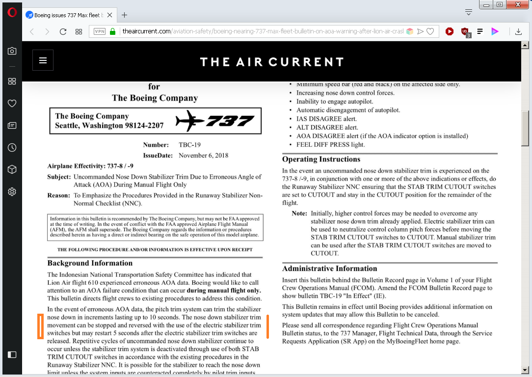
Last edited by jimjim1; 6th Apr 2019 at 23:51.
Join Date: May 2016
Location: Nantes
Posts: 63
Likes: 0
Received 0 Likes
on
0 Posts
The pilots of the 2 last Lion Air flights did it. The Copilot in Lion Air crash and the Captain in ET302 did not. That's only 50% !
By the way, when speaking that an "average pilot" should be enough to succeed avoiding a crash, it implies that the crash probability is very near 50%, since by definition 49,99% of the pilots are higher than average and 49,99% under average

Join Date: Jun 2001
Location: Rockytop, Tennessee, USA
Posts: 5,898
Likes: 0
Received 1 Like
on
1 Post
Here's an explanation of the EASA position on the observation that the yoke trim switches on the MAX don't work throughout the entire speed envelope (with some highlighted text):
From: https://www.easa.europa.eu/sites/def...20ISS%2010.pdf
Explanatory Note to TCDS IM.A.120 – Boeing 737 Issue 10
EQUIVALENT SAFETY FINDING:
B-05/MAX: Longitudinal trim at Vmo
APPLICABILITY: Boeing B737-7/-8/-9 REQUIREMENTS: CS 25.161(a), CS 25.161(c)(3), CS 25.1301(a) and CS 25.1309(a) ADVISORY MATERIAL: N/A
STATEMENT OF ISSUE
The aisle stand trim switches can be used to trim the airplane throughout the flight envelope and fully complies with the reference regulation. Simulation has demonstrated that the thumb switch trim does not have enough authority to completely trim the aircraft longitudinally in certain corners of the flight envelope, e.g. gear up/flaps up, aft center of gravity, near Vmo/Mmo corner, and gear down/flaps up, at speeds above 230 kts. In those cases, longitudinal trim is achieved by using the manual stabilizer trim wheel to position the stabilizer. The trim wheel can be used to trim the airplane throughout the entire flight envelope. In addition, the autopilot has the authority to trim the airplane in these conditions. The reference regulation and policy do not specify the method of trim, nor do they state that when multiple pilot trim control paths exist that they must each independently be able to trim the airplane throughout the flight envelope. Boeing did not initially consider this to be a compliance issue because trim could always be achieved, even during the conditions where use of the aisle stand trim switch was required. Subsequent to flight testing, the FAA-TAD expressed concern with compliance to the reference regulation based on an interpretation of the intent behind “trim”. The main issue being that longitudinal trim cannot be achieved throughout the flight envelope using thumb switch trim only.
EASA POSITION
Boeing set the thumb switch limits in order to increase the level of safety for out-of-trim dive characteristics (CS 25.255(a)(1)). The resulting thumb switch limits require an alternative trim method to meet CS 25.161 trim requirements in certain corners of the operational envelope.
The need to use the trim wheel is considered unusual, as it is only required for manual flight in those corners of the envelope.
The increased safety provided by the Boeing design limits on the thumb switches (for out-of-trim dive characteristics) provides a compensating factor for the inability to use the thumb switches throughout the entire flight envelope. Furthermore, the additional crew procedures and training material will clearly explain to pilots the situations where use of the trim wheel may be needed due to lack of trim authority with the wheel mounted switches.
The trim systems on the 737Max provide an appropriate level of safety relative to longitudinal trim capability.
Page 15 of 114
Not so. Step 2 is "Autopilot (if engaged) disengage". A/P was no longer engaged. So forget Step 2. Even if you don't, it says "Control pitch with column and trim". The pitch has been controled, the trim was back at the limit of green band though a significative column force remained.
Never is said to use electric trim to full trim before cutout, nor any warning that manuel trim might be impossible at higher mistrim/speeds
Never is said to use electric trim to full trim before cutout, nor any warning that manuel trim might be impossible at higher mistrim/speeds
Join Date: May 2016
Location: Nantes
Posts: 63
Likes: 0
Received 0 Likes
on
0 Posts
At the end of the flight they got -2g with still both pilots applying full aft force !