


Air Canada A320 accident at Halifax

Join Date: Mar 2015
Location: Coastal Georgia
Age: 71
Posts: 40
Likes: 0
Received 0 Likes
on
0 Posts
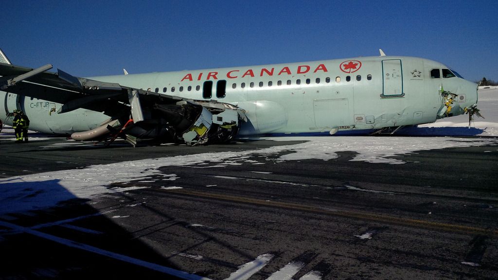
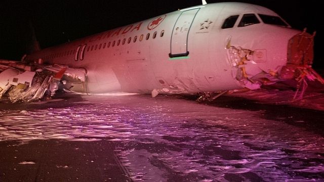
RH Wing Too
To collect what looks to be part of the 23 ILS localiser array with the radome they must have touched down a fair distance short of the threshold.

Join Date: Aug 2006
Location: Canada
Posts: 14
Likes: 0
Received 0 Likes
on
0 Posts
Jet Jockey A4 We don't have the info for the runway conditions but I wonder why they didn't use RWY 32 with those winds?
29th Mar 2015 15:16
CYHZ RSC 05/23 120 FT CL 70 PCT WET SN TRACE, 30 PCT BARE AND DAMP.
REMAINING WID 100 PCT WET SN 0.75 INS. RMK: SNOW REMOVAL IN
PROGRESS.. 2 FT SN BANK 10 FT OUTSIDE NORTH AND SOUTH RWY EDGE.
1503290115
CYHZ CRFI 05/23 -5C .36 1503290115
CYHZ RSC 14/32 80 PCT SN DRIFTS 1.5 INS, 20 PCT BARE AND DAMP. 2 FT
SN BANK 10 FT OUTSIDE EAST AND WEST RWY EDGE. 1503290117
RMK: TWY ALPHA, JULIET, KILO, WET SNOW 100 PCT, TRACE BRAVO,
CHARLIE, WET SNOW 100 PCT, 1 1/2IN DELTA LONG, ECHO, FOXTROT, GOLF,
HOTEL, MIKE, WET SNOW 100 PCT, 1IN DELTA SHORT, WET SNOW 100 PCT,
1/8IN
Join Date: May 2010
Location: Wheaton, IL
Posts: 7
Likes: 0
Received 0 Likes
on
0 Posts
Re: voltage of power lines and burying them
I'm afraid I can't remember the voltage used - that found across the top outer wires - but I'm fairly sure it's in the thousands. It's hard to bury that kind of voltage, and to drop it, and then raise it again, would be horribly expensive.
It is extremely common and is very feasible to bury 12.9kV or 20kV conductors. This is done all the time for commercial underground service drops in more urban areas. An airport near where I live has several 34.5kV circuits that are in fact buried just at the point that they cross the runway even though they are several hundred feet past the airport fence. The bottom line is it would be very, very feasible to bury the lines around the ends of the airport (or simply route them in a different route away from the runways.) That said, the top of the power lines appear to be about level with the runway in this case and I imagine that the designers figured that hitting the power lines was probably the least of their concerns on this particular approach since there appears to be terrain and antennas that the plane would also impact if it were that low.
Join Date: Aug 2008
Location: KSAN
Age: 62
Posts: 27
Likes: 0
Received 0 Likes
on
0 Posts
Even less expensive would be clearing a new right-of-way and running that line further downhill. However, those lines are already significantly below threshold height.
Maybe a better investment would be RNAV capability in all AC 320s?
Maybe a better investment would be RNAV capability in all AC 320s?

Join Date: Mar 2015
Location: Canada
Posts: 1
Likes: 0
Received 0 Likes
on
0 Posts
LOC antenna
The burm on which the LOC antenna is placed is aprx 1000ft from the runway threshold. This aircraft had to be quite low to clean out portions of the antenna. This investigation will be interesting for sure.
Join Date: Aug 2012
Location: Hawarden (near EGNR)
Age: 74
Posts: 84
Likes: 0
Received 0 Likes
on
0 Posts
In the UK, 33 kV 3-phase on wooden poles are common. Similar height. And often re-routed underground for new housing or other development.
Typically, the 33 kV then reduced to 11 kV for local distribution to either ground or pole mounted 11 kV to 400/230 volt for houses and commercial use.
(When at sea, on my last few containerships we generated at 6.6 kV with a total capacity of about 10 MW - not that we would have all running at once! This was for cargo refrigeration etc NOT for propulsion, we had a circa 30 MW slow speed diesel for that)
Join Date: Nov 2004
Location: Home
Posts: 21
Likes: 0
Received 0 Likes
on
0 Posts
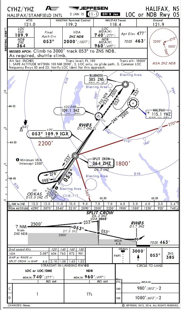
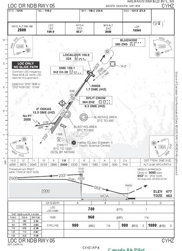
Approach Chart for LOC/DME RWY 05
Please, can someone post an image of the Jeppesen approach chart for runway 05.
I'd like to do some calculations.
Non Precision Approaches continue to present problems, and are statistically responsible for the majority of CFIT accidents.
Someone mentioned earlier UPS and Birmingham. There seem to be many similarities.
Does the approach chart have a height/distance table? I would guess not. This would have greatly helped situational awareness, as it would have in Birmingham.
Join Date: Jan 2008
Location: Bracknell, Berks, UK
Age: 52
Posts: 1,133
Likes: 0
Received 0 Likes
on
0 Posts
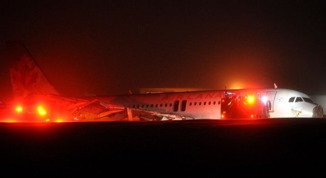
Air Canada plane passenger: 'I thought we were goners' - BBC News and specifically the second interview with a passenger seems to imply that it was forced up into the belly of the aircraft during one of the bounces.
Join Date: Jun 2008
Location: Ventura, California
Age: 65
Posts: 262
Likes: 0
Received 0 Likes
on
0 Posts
Google Earth shows the road being about 2290 feet southwest and 31 feet below the TDZ. I wonder if they mistook something else for the runway and descended below MDA too soon. Or it could have been power loss, or, or, or.......
Join Date: May 2002
Location: Sale
Posts: 374
Likes: 0
Received 0 Likes
on
0 Posts
Looking at the chart, I can't, immediately, see any difficulties.
Interesting to note, MSA 2800 ft within 100nm. i.e. pretty flat.
That doesn't mean that there aren't obstacle threats close to the runway.
It will be interesting to see what went wrong on this particular day.
Interesting to note, MSA 2800 ft within 100nm. i.e. pretty flat.
That doesn't mean that there aren't obstacle threats close to the runway.
It will be interesting to see what went wrong on this particular day.
Join Date: Nov 2004
Location: Home
Posts: 21
Likes: 0
Received 0 Likes
on
0 Posts
Threshold Distance or Localizer Distance?
It is interesting to note that if the threshold distance was used in error instead of the localizer distance, then when following the height/distance table, the aircraft would be approx 550' low at every height/distance check point.
The figures look like this:
Using THR 05 distance, this is the required height/distance:
6/2470, 5/2150, 4/1820, 3/1490, 2.4/1298.
Using IHZ DME, this is the required height/distance:
6/1900, 5/1580, 4/1250, 3/920, 2.4/740.
So by using threshold distance and flying the corresponding height for localizer distance, the aircraft will fly a similar descent angle but will be approx 550' low.
Not saying this is what happened, but it is a possible scenario.
Join Date: Dec 2004
Location: In Hyperspace...
Posts: 395
Likes: 0
Received 0 Likes
on
0 Posts
IHZ DME is the reference quoted on the plate descent profiles, ending at 2.4 miles @ 740' - seems right for a std 3 deg appch. The plates don't make it obvious, however, that the DME isn't zeroed @ threshold.
Still, shouldn't one level @MDA if you don't have vis refs? And if you have vis refs, it's difficult to explain landing short in the absence of any other problem?
Still, shouldn't one level @MDA if you don't have vis refs? And if you have vis refs, it's difficult to explain landing short in the absence of any other problem?
Join Date: Jul 2004
Location: Found in Toronto
Posts: 615
Likes: 0
Received 0 Likes
on
0 Posts
@N707ZS,
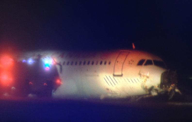
If the plane was doing about 150mph at the time, that's 240km/h, approx 60meter/sec. With 60Hz mains in Canada that would be a full cycle of AC mains electricity every meter travelled by the aircraft. If there were an arc generated at the peak +ve & -ve voltage that would occur at 120Hz, or about every 50 centimeter travelled by the aircraft.
I'd say that's a pretty close correlation to the apparent spacing between the "burn marks" in that photo, so I fear that that is what they actually are.
Join Date: Jun 2005
Location: Canada
Posts: 5
Likes: 0
Received 0 Likes
on
0 Posts
FlyinTrim....the FPA isnt calculated off the DME. This approach would be flown in LOC/FPA. You would descend down to 2000' for the FAF and then at the FAF it would be FPA -3.0 (plus temp correction) down to your MDA. The only DME you would need is where you can descend down to 2000' but that doesn't seem to be the problem here.
Or am I missing what you are saying?
Or am I missing what you are saying?