


Emirates A330 Fan Blade - DXB 18 Oct

Join Date: Feb 2005
Location: flyover country USA
Age: 82
Posts: 4,579
Likes: 0
Received 0 Likes
on
0 Posts
I think you have most of the elements in place, but I might propose a slightly different sequence:
At low power during descent & approach, the bleed air isn't so hot. But if it was stuck on during the long cruise, that could have damaged the regulating servo in the valve.
But then in the GA with hot ambient, the overtemp/overpressure from the failed regulator could have blown things apart.
See my comments above.
This is only a postulation that might serve to provide some additional thoughts and checks to some confirmed reasoning.
May I borrow your disclaimer? 
But then in the GA with hot ambient, the overtemp/overpressure from the failed regulator could have blown things apart.
Then if the engine were increased to very high power while the aircraft was at low speed, with less ram air into the inlet, the sucking pressure drop across the inlet would act on inner panels and possibly delaminate them at their attachments. Since the inlet walls are made as panels, only the weakest one would fail.
This is only a postulation that might serve to provide some additional thoughts and checks to some confirmed reasoning.

Join Date: Oct 2006
Location: in a house
Posts: 5
Likes: 0
Received 0 Likes
on
0 Posts
The Intake wasnt bumped at bhx,there are too many people around to not notice let alone thinking they could get away with it.A reliable source tells me.
Why not wait until the official report as these wild theories are just that WILD.
Why not wait until the official report as these wild theories are just that WILD.
Join Date: Dec 1998
Location: .
Posts: 2,997
Likes: 0
Received 0 Likes
on
0 Posts
From the Airbus manual: (well I put the pics in!)
In my opinion very unlikely that the NAI system caused the damage, as it's not really anywhere near where the damage has occured, even if the NAI valve was stuck open it just vents overboard anyway.
30-21-00 PB 001 - ENGINE AIR INTAKE ICE PROTECTION - DESCRIPTION AND OPERATION
1. General
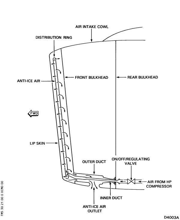
The engine air intake ice protection system gives a flow of hot air from the engine to the intake cowl. The system is in two parts:
- On the core engine: A duct goes from the engine off-take (the 3rd stage of the HP compressor) to the intake cowl interface.
- In the intake cowl, from the interface to a distribution ring in the space behind the lip skin
3. System Description
Between the core engine and the distribution ring the system has two venturis and an engine air intake cowl anti-ice valve (4000DN). Bolts attach one of the ducts to the core engine. Clamps hold the ducts together. Clamps also keep the ducts in position at the rear bulkhead of the intake cowl. A seal is installed in the joints between the ducts. There are two bleed points that are downstream of the engine air intake cowl anti-ice valve (4000DN). One bleed point goes to a high pressure switch (4069KS) on the valve. The other bleed point goes to a low pressure switch (4001DN) on the valve.
In the intake cowl the system has a distribution ring and an inter-bulkhead assembly. The distribution ring is installed between the front bulkhead and the lip skin. It cannot be removed. The inter-bulkhead assembly is in two parts, the inner duct and the outer duct. Each part can be removed. Seals prevent air leakage around the ends of the two ducts.
5. Interface
The system has interfaces with the core engine, the aircraft electrical system and the aircraft instrument system. The low pressure switch (4001DN) gives an indication to the aircraft instrument system when; the valve has opened and there is pressure in the duct downstream of the valve. This signal is stopped when the valve is closed and the duct pressure downstream of the valve decreases.
The high pressure switch (4069KS) gives a signal to the aircraft instrument system when these conditions occur; there is too much pressure downstream of the valve and, if the control function of the valve does not operate correctly. The interface with the core engine gives the system continuity of airflow between the areas that follow; the HP compressor off-take and the lip skin. The engine air intake cowl anti-ice valve (4000DN) has interfaces with the aircraft electrical system and the aircraft instrument system.
6. Component Description
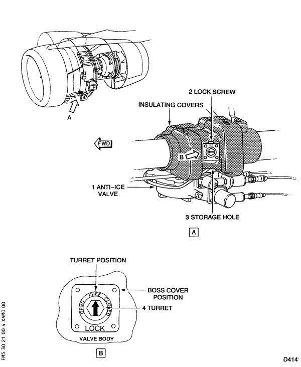
A. The Engine Air Intake Cowl Anti-Ice Valve (4000DN):
The primary components of the engine air intake cowl anti-ice valve (4000DN) are:
- the valve body
- the butterfly shut-off valve
- the pneumatic actuator/regulator
- the electrical solenoid
- the HP and LP pressure switches (4069KS and 4001DN).
All the components are attached to, or installed in, the valve body. A 'direction of flow' arrow on the valve body shows the correct position to install and align the valve. The spindle of the butterfly shut-off valve has a hexagon end for manual operation of the valve. The valve locking pin can be installed through the pointer handle and into a flange on the valve body. This will stop the movement of the butterfly valve.
The valve body has a machined flange at each end to connect the anti-icing ducts. The butterfly shut-off valve is a precision fit in the valve body. The shut-off valve can seal the airflow through the engine air intake cowl anti-ice valve (4000DN). The pneumatic actuator is attached to the valve body. It is mechanically connected to the butterfly shut-off valve and the position switch.
B. The Inter-Bulkhead Assembly (The Inner and Outer Ducts):
The inner duct is made from two different diameters of tube that are welded together. These make a divergent venturi at the forward end. There is a mechanical connection welded to each end of the inner duct. One end connects to the distribution ring, the other end connects to the bulkhead attachment.
The connections at the ends of the inner duct can move to let the inner duct become longer when it gets hot. The bulkhead attachment makes a converging venturi which is a flow restrictor during system operation.
The outer duct is a rigid assembly with three openings. The small opening at the aft bulkhead has a machined connection welded to it. This opening is installed into the bulkhead attachment and can move (to let the outer duct get longer when it becomes hot). The larger opening at the forward bulkhead is attached by a clamp to a connection. This connection is attached to the forward bulkhead by rivets.
The opening on the side of the duct has a seal around it. This seal is pushed against the anti-ice air outlet-grille on installation. An insulation blanket covers the side of the outer duct that is nearest to the inner barrel (of the intake cowl). This prevents damage to the inner barrel (caused by the high temperatures of the outer duct).
C. The Distribution Ring:
The distribution ring is a rigid duct which is permanently attached to the intake cowl. It is in the space behind the lip skin and it connects with the inner duct of the inter-bulkhead assembly. The distribution ring has rows of small supply holes around it.
7. Operation/Control and Indicating
Air from the 3rd stage of the HP compressor flows to the engine air intake cowl anti-ice valve (4000DN) through the anti-ice ducts. The first venturi assembly (which is under the left fan cowl) limits the quantity of airflow through the ducts. This makes sure that the engine keeps the necessary performance if the system gets a leak downstream of the first venturi. The first venturi does not affect the satisfactory operation of the system.
The engine air intake cowl anti-ice valve (4000DN) uses the upstream air pressure for its pneumatic operation. The electrical solenoid controls the flow of the upstream air into the pneumatic actuator. When the system is pressurized and the electrical power is removed from the electrical solenoid, the valve controls the pressure to 62 PSIg (427KPa). If the system stays pressurized, and the electrical solenoid is energized, the valve will close. With no upstream air pressure the valve stays open if the electrical solenoid is energized or has its electrical power removed.
The air from the engine air intake cowl anti-ice valve (4000DN) flows through the anti-ice ducts to the inter-bulkhead assembly. The inner duct of the inter-bulkhead assembly connects the distribution ring to the anti-ice ducts.
The air in the distribution ring flows out through small supply holes and into the space between the lip skin and the front bulkhead. The hot air increases the temperature of the lip skin and gives ice protection to the air intake.
Used anti-ice air flows to the anti-ice outlet-grille through the outer duct of the inter-bulkhead assembly (Ref. Fig. 003). The seals on the connections of the inter-bulkhead assembly prevent the flow of anti-ice air to other areas of the air intake.
With no upstream air pressure, the engine air intake cowl anti-ice valve (4000DN) can be manually operated with an applicable hand wrench. If the valve is put in the fully open position, the locking pin can be installed in the lock hole. The locking pin can also be installed in the lock hole when the valve is in the fully closed position. With the locking pin in the lock hole the pneumatic actuator (and thus the valve) is locked in position.
1. General
The engine air intake ice protection system gives a flow of hot air from the engine to the intake cowl. The system is in two parts:
- On the core engine: A duct goes from the engine off-take (the 3rd stage of the HP compressor) to the intake cowl interface.
- In the intake cowl, from the interface to a distribution ring in the space behind the lip skin
3. System Description
Between the core engine and the distribution ring the system has two venturis and an engine air intake cowl anti-ice valve (4000DN). Bolts attach one of the ducts to the core engine. Clamps hold the ducts together. Clamps also keep the ducts in position at the rear bulkhead of the intake cowl. A seal is installed in the joints between the ducts. There are two bleed points that are downstream of the engine air intake cowl anti-ice valve (4000DN). One bleed point goes to a high pressure switch (4069KS) on the valve. The other bleed point goes to a low pressure switch (4001DN) on the valve.
In the intake cowl the system has a distribution ring and an inter-bulkhead assembly. The distribution ring is installed between the front bulkhead and the lip skin. It cannot be removed. The inter-bulkhead assembly is in two parts, the inner duct and the outer duct. Each part can be removed. Seals prevent air leakage around the ends of the two ducts.
5. Interface
The system has interfaces with the core engine, the aircraft electrical system and the aircraft instrument system. The low pressure switch (4001DN) gives an indication to the aircraft instrument system when; the valve has opened and there is pressure in the duct downstream of the valve. This signal is stopped when the valve is closed and the duct pressure downstream of the valve decreases.
The high pressure switch (4069KS) gives a signal to the aircraft instrument system when these conditions occur; there is too much pressure downstream of the valve and, if the control function of the valve does not operate correctly. The interface with the core engine gives the system continuity of airflow between the areas that follow; the HP compressor off-take and the lip skin. The engine air intake cowl anti-ice valve (4000DN) has interfaces with the aircraft electrical system and the aircraft instrument system.
6. Component Description
A. The Engine Air Intake Cowl Anti-Ice Valve (4000DN):
The primary components of the engine air intake cowl anti-ice valve (4000DN) are:
- the valve body
- the butterfly shut-off valve
- the pneumatic actuator/regulator
- the electrical solenoid
- the HP and LP pressure switches (4069KS and 4001DN).
All the components are attached to, or installed in, the valve body. A 'direction of flow' arrow on the valve body shows the correct position to install and align the valve. The spindle of the butterfly shut-off valve has a hexagon end for manual operation of the valve. The valve locking pin can be installed through the pointer handle and into a flange on the valve body. This will stop the movement of the butterfly valve.
The valve body has a machined flange at each end to connect the anti-icing ducts. The butterfly shut-off valve is a precision fit in the valve body. The shut-off valve can seal the airflow through the engine air intake cowl anti-ice valve (4000DN). The pneumatic actuator is attached to the valve body. It is mechanically connected to the butterfly shut-off valve and the position switch.
B. The Inter-Bulkhead Assembly (The Inner and Outer Ducts):
The inner duct is made from two different diameters of tube that are welded together. These make a divergent venturi at the forward end. There is a mechanical connection welded to each end of the inner duct. One end connects to the distribution ring, the other end connects to the bulkhead attachment.
The connections at the ends of the inner duct can move to let the inner duct become longer when it gets hot. The bulkhead attachment makes a converging venturi which is a flow restrictor during system operation.
The outer duct is a rigid assembly with three openings. The small opening at the aft bulkhead has a machined connection welded to it. This opening is installed into the bulkhead attachment and can move (to let the outer duct get longer when it becomes hot). The larger opening at the forward bulkhead is attached by a clamp to a connection. This connection is attached to the forward bulkhead by rivets.
The opening on the side of the duct has a seal around it. This seal is pushed against the anti-ice air outlet-grille on installation. An insulation blanket covers the side of the outer duct that is nearest to the inner barrel (of the intake cowl). This prevents damage to the inner barrel (caused by the high temperatures of the outer duct).
C. The Distribution Ring:
The distribution ring is a rigid duct which is permanently attached to the intake cowl. It is in the space behind the lip skin and it connects with the inner duct of the inter-bulkhead assembly. The distribution ring has rows of small supply holes around it.
7. Operation/Control and Indicating
Air from the 3rd stage of the HP compressor flows to the engine air intake cowl anti-ice valve (4000DN) through the anti-ice ducts. The first venturi assembly (which is under the left fan cowl) limits the quantity of airflow through the ducts. This makes sure that the engine keeps the necessary performance if the system gets a leak downstream of the first venturi. The first venturi does not affect the satisfactory operation of the system.
The engine air intake cowl anti-ice valve (4000DN) uses the upstream air pressure for its pneumatic operation. The electrical solenoid controls the flow of the upstream air into the pneumatic actuator. When the system is pressurized and the electrical power is removed from the electrical solenoid, the valve controls the pressure to 62 PSIg (427KPa). If the system stays pressurized, and the electrical solenoid is energized, the valve will close. With no upstream air pressure the valve stays open if the electrical solenoid is energized or has its electrical power removed.
The air from the engine air intake cowl anti-ice valve (4000DN) flows through the anti-ice ducts to the inter-bulkhead assembly. The inner duct of the inter-bulkhead assembly connects the distribution ring to the anti-ice ducts.
The air in the distribution ring flows out through small supply holes and into the space between the lip skin and the front bulkhead. The hot air increases the temperature of the lip skin and gives ice protection to the air intake.
Used anti-ice air flows to the anti-ice outlet-grille through the outer duct of the inter-bulkhead assembly (Ref. Fig. 003). The seals on the connections of the inter-bulkhead assembly prevent the flow of anti-ice air to other areas of the air intake.
With no upstream air pressure, the engine air intake cowl anti-ice valve (4000DN) can be manually operated with an applicable hand wrench. If the valve is put in the fully open position, the locking pin can be installed in the lock hole. The locking pin can also be installed in the lock hole when the valve is in the fully closed position. With the locking pin in the lock hole the pneumatic actuator (and thus the valve) is locked in position.
The NAI is designed to add BTU's to the inlet system to raise the inner air temp quite a bit above freezing, such that it is effective at shedding ice on the inner barrel before it builds up enough to seriously damage the engine. This already presumes the flow in the diagram you posted. So if the skin temp against the ice is already 80 deg C. the delta rise on the inside where the anti-ice-air is will be quite a bit above this.
Secondly the system is designed to provide uniform heating even with the inlet and exit flow (baffles etc.) so to me it's a toss up what inner panel is the weakest and fail first.
I realize that I am not adding any more insight here, but rather just extending my original postulation.
Of course I am entirely prepared for a crow sandwich when Airbus releases an all operator letter on this blaming something else
Spanneratcx's description of the NAI system indicates that there should be no anti-ice air in the cowl between the front bulkhead and the rear bulkhead on the diagram. The anti-ice air should be confined to the cowl lip area only if I have understood the description correctly. Yet the area that suffered the failure of both inner and outer skins in the incident engine is behind the forward bulkhead.
Question; if high pressure anti-ice air at regulated 62 PSI (or higher if unregulated), entered the area between the forward and rear bulkheads, where could this air escape to atmosphere such that a destructive overpressure could not build up in the subject area?
What failure mode of the NAI delivery ducting or regulating valve could result in allowing pressure-regulated anti-ice air or unregulated pressure into this area?
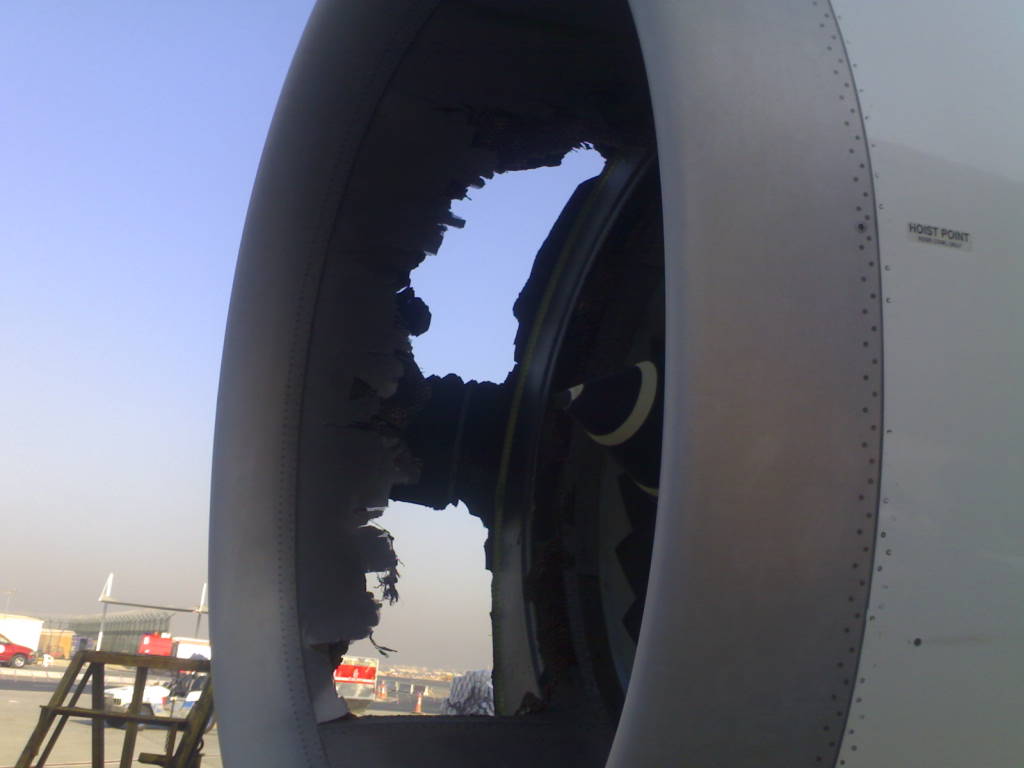
paulkinm's photo
Question; if high pressure anti-ice air at regulated 62 PSI (or higher if unregulated), entered the area between the forward and rear bulkheads, where could this air escape to atmosphere such that a destructive overpressure could not build up in the subject area?
What failure mode of the NAI delivery ducting or regulating valve could result in allowing pressure-regulated anti-ice air or unregulated pressure into this area?
paulkinm's photo
Join Date: May 2003
Location: eastmidlands
Age: 62
Posts: 41
Likes: 0
Received 0 Likes
on
0 Posts
Wrong!!!

Steve to clarify!
Emirates reported no damage at BHX but are investigating - Some sort of doubt?
However, an earlier post was most likely on the right lines:-
Some sort of hidden cowl defect or a combination of both a defect and the engine overspeeding, with the engine ingesting its own cowling on approach.
The runways were switched at last minute and the aircraft ended up out of shape on the approach with the crew attempting a go round at 400ft and its engine ending up overspeeding (107%).
Join Date: Jan 1999
Location: hongkong
Posts: 187
Likes: 0
Received 0 Likes
on
0 Posts
Would have thought that the overspeed was a result of the blocked inlet not the other way around.
If a depression at the fan was the reason why didn't the cowl 'let go' at BHX when the a/c spooled up for T/O and the depression was the greatest?
At 140 knots or so when the G/A would have been initiated there would have been lots of pressure in the inlet methinks even with the engine going full tilt!
Join Date: Mar 2005
Location: Earth
Posts: 62
Likes: 0
Received 0 Likes
on
0 Posts
if not already mentioned:
http://www.flickr.com/photos/98001721@N00/
http://www.flickr.com/photos/98001721@N00/
Thread Starter
Join Date: Mar 2004
Location: Hull
Posts: 8
Likes: 0
Received 0 Likes
on
0 Posts
What was the reason for the G/A?
Earlier in this thread, someone mentioned that the GA was initiated due to a late runway change by ATC. Isn't their only one active RW at DXB at the moment? It looked to me like the other one was a mass of sand and hardcore....
Join Date: Feb 2007
Location: St Sardos, France
Posts: 69
Likes: 0
Received 0 Likes
on
0 Posts
Indeed when we saw these pics on the corporate site it was a case of WOW how did that happen. It wouls be nice to see the final report. RR also said that the engine performed normally post incident well thats good to hear anyway.
