


Category A PC1 or PC2


Joined: May 2003
Posts: 921
Likes: 30
From: Europe
My apologies for intruding on other threads but a revised document that includes more figures is now available.
The introduction and evolution of Category A procedures - from runways to heliports in city centres
Enjoy - and feel free to circulate.
Jim
The introduction and evolution of Category A procedures - from runways to heliports in city centres
Enjoy - and feel free to circulate.
Jim

Joined: May 2003
Posts: 921
Likes: 30
From: Europe
During the middle part of this thread, there was a discussion on the graphs and other data included in the Category A Supplements. Given that discussion, and after a conversation with a friend with more knowledge than I could ever have, the following is offered in explanation of the process of producing, and the contents of, those Supplements.
Hopefully, others will take the opportunity to add their comments and experiences.
Exploring Category A design and testing and the contents of the Category A Supplement
The design, development, testing and certification of a Category A procedure � other than the clear area/runway, which is a basic element of Category A certification, is an expensive undertaking for which recovery of cost can be achieved only through the sale of aircraft. It results from an operational requirement that is either part of the perceived role of a type (such as air ambulance in the case of the small and medium twins) or, as a request from an important user group (such as the oil companies in the case of offshore operations).
The design and testing process
The design and testing process for each of the procedures, although specific to each manufacturer, would follow a similar path. The example below starts with the establishment of the basic elements of Category A Performance before progressing to the definition of a clear area/runway, and Vertical, Procedure.
1. First, all of the trim flight performance testing (hover, level flight, climb and descent) is carried out in fully instrumented helicopters and ideal conditions. Parametric power required data maps and a trim flight performance computer model are developed.
2. Engine inlet and exhaust surveys and installed engine power available verification testing are carried out, and the installed engine power available computer model is obtained from the engine manufacturer.
3. The Category A second segment WAT curve is then calculated using the results of 1 and 2. Note that the Category A second segment WAT curve gives the absolute maximum possible Category A weight for altitude and temperature.
4. The lowest Vtoss at which the Category A first segment WAT curve, at least equal to the Category A second segment WAT curve, is determined using the results of 1 and 2.
5. The Category A airfield procedure is developed by flight testing at the WAT curve determined in step 3. using Vtoss from step 4.
6. Category A first segment WAT curves are then calculated for reduced Vtoss values using the results of 1 and 2. Note that these result in lower weights when adjusted for altitude and temperature.
7. The airfield Category A field length data maps are then developed by flight testing at WAT limiting conditions for all selectable Vtoss values.
8. While the airfield WAT curves are based on trim OEI climb performance minima, vertical procedure WAT curves are based on low-speed dynamic performance - that is, the ability to transition from AEO flight at TDP to OEI flight at Vtoss, or from AEO flight at TDP to OEI for a reject.
9. Low-speed dynamic performance data are acquired during vertical climb and descent, and OEI[1] reject and flyaway, with engine failures occurring over a wide range of weights, TDP heights, and Vtoss values. These data are used to align a Low-Speed Dynamic Performance computer model.
10. A Vertical Procedure WAT curve is calculated using the correlated computer model (mentioned above) and compared with the Category A first segment WAT curve - to confirm that first segment OEI climb performance minima are also achievable.
11. The final WAT curve is validated by conducting OEI reject and flyaway tests at WAT limiting conditions over the established range of TDP heights and Vtoss values.
12. While the above addresses the take-off case, the Category A airfield and Vertical Procedure landing procedures are developed similarly.
13. The final procedures are reproduced in the RFM and observed, or flown, by the authority test pilots during the acceptance and certification process.
Where appropriate, nomogram format charts are used to present multivariate performance information on a single RFM page. Rate of Climb (ROC), which is a function of engine power, mass, altitude, temperature, and airspeed, is typically presented using a nomogram format chart. ROC charts are constructed by first calculating the ROC for specific engine power ratings and airspeeds at many discrete points over the range of mass, altitudes, and temperatures that define the operating envelope of the helicopter. With the use of regression analyses, the resulting data are correlated and compressed into nomogram format charts. This technique is also used to construct the take-off and landing WAT curves as a function of Vtoss.
Contents of the Category A Supplement
The Category A Supplement is contained in the Approved Section of the RFM; it contains one, or all, of the Category A procedures[2] that are required to ensure that the helicopter is capable of meeting its full potential (note that in some manuals the clear area/runway procedure is contained in the basic part of the RFM along with the Category A WAT and performance data). The contents would normally consist of:
A general part that includes: terminology and definitions; useful information about the choice of a procedure; limitations and general performance data, all of which apply to any/all of the approved procedures.
A number of individual parts, each applicable to a specific procedure containing: limitations; normal procedures (including diagrams and pictures); emergency and malfunction procedures; and performance data.
Flight profile diagrams, FOV pictures and, with the use of relevant examples step-by-step instructions to the pilot for using the graphs and data for establishing the required parameters and distances to match the profile to the heliport data, are provided. The pilots required actions during normal, malfunction and emergency procedures are described in detail. Flight outside the relevant WAT or flight profile invalidates the procedure and could, in the event of an engine failure, result in other than a safe landing or continued flight.
Vertical Procedures rely upon the accurate determination of mass and, during the piloting phase, precise control of: power - through control of rotor speed (Nr); attitude; and height. Whilst failure to apply the procedure as defined might not result in unforeseen consequences, there are critical points in the procedure/profile where the risk is greatest and at which testing has been concentrated. These are the (pre-determined) intervention time immediately preceding TDP and LDP. As the profile tends away from those points, the risk lessens, and the consequences of an engine failure diminish; however, that should not be seen as an opportunity for casual observance of the sequence, parameters, or limitations of the procedure - the responsibility for occupants and third parties rests on the shoulders of the pilot(s).
[1] To avoid employing the 0EI, 30-second setting with its potential for destructive consequences during flight testing, the power, or the total aircraft torque, may be artificially limited by using a specially adapted FADEC mode (as it currently is for pilot training). This can then be compared to the engine power available in the provision of the WAT graph.
[2] This does not include any procedures that have been developed to satisfy an operational regulation, request, or requirement and are contained in the non-approved section.
Hopefully, others will take the opportunity to add their comments and experiences.
Exploring Category A design and testing and the contents of the Category A Supplement
The design, development, testing and certification of a Category A procedure � other than the clear area/runway, which is a basic element of Category A certification, is an expensive undertaking for which recovery of cost can be achieved only through the sale of aircraft. It results from an operational requirement that is either part of the perceived role of a type (such as air ambulance in the case of the small and medium twins) or, as a request from an important user group (such as the oil companies in the case of offshore operations).
The design and testing process
The design and testing process for each of the procedures, although specific to each manufacturer, would follow a similar path. The example below starts with the establishment of the basic elements of Category A Performance before progressing to the definition of a clear area/runway, and Vertical, Procedure.
1. First, all of the trim flight performance testing (hover, level flight, climb and descent) is carried out in fully instrumented helicopters and ideal conditions. Parametric power required data maps and a trim flight performance computer model are developed.
2. Engine inlet and exhaust surveys and installed engine power available verification testing are carried out, and the installed engine power available computer model is obtained from the engine manufacturer.
3. The Category A second segment WAT curve is then calculated using the results of 1 and 2. Note that the Category A second segment WAT curve gives the absolute maximum possible Category A weight for altitude and temperature.
4. The lowest Vtoss at which the Category A first segment WAT curve, at least equal to the Category A second segment WAT curve, is determined using the results of 1 and 2.
5. The Category A airfield procedure is developed by flight testing at the WAT curve determined in step 3. using Vtoss from step 4.
6. Category A first segment WAT curves are then calculated for reduced Vtoss values using the results of 1 and 2. Note that these result in lower weights when adjusted for altitude and temperature.
7. The airfield Category A field length data maps are then developed by flight testing at WAT limiting conditions for all selectable Vtoss values.
8. While the airfield WAT curves are based on trim OEI climb performance minima, vertical procedure WAT curves are based on low-speed dynamic performance - that is, the ability to transition from AEO flight at TDP to OEI flight at Vtoss, or from AEO flight at TDP to OEI for a reject.
9. Low-speed dynamic performance data are acquired during vertical climb and descent, and OEI[1] reject and flyaway, with engine failures occurring over a wide range of weights, TDP heights, and Vtoss values. These data are used to align a Low-Speed Dynamic Performance computer model.
10. A Vertical Procedure WAT curve is calculated using the correlated computer model (mentioned above) and compared with the Category A first segment WAT curve - to confirm that first segment OEI climb performance minima are also achievable.
11. The final WAT curve is validated by conducting OEI reject and flyaway tests at WAT limiting conditions over the established range of TDP heights and Vtoss values.
12. While the above addresses the take-off case, the Category A airfield and Vertical Procedure landing procedures are developed similarly.
13. The final procedures are reproduced in the RFM and observed, or flown, by the authority test pilots during the acceptance and certification process.
Where appropriate, nomogram format charts are used to present multivariate performance information on a single RFM page. Rate of Climb (ROC), which is a function of engine power, mass, altitude, temperature, and airspeed, is typically presented using a nomogram format chart. ROC charts are constructed by first calculating the ROC for specific engine power ratings and airspeeds at many discrete points over the range of mass, altitudes, and temperatures that define the operating envelope of the helicopter. With the use of regression analyses, the resulting data are correlated and compressed into nomogram format charts. This technique is also used to construct the take-off and landing WAT curves as a function of Vtoss.
Contents of the Category A Supplement
The Category A Supplement is contained in the Approved Section of the RFM; it contains one, or all, of the Category A procedures[2] that are required to ensure that the helicopter is capable of meeting its full potential (note that in some manuals the clear area/runway procedure is contained in the basic part of the RFM along with the Category A WAT and performance data). The contents would normally consist of:
A general part that includes: terminology and definitions; useful information about the choice of a procedure; limitations and general performance data, all of which apply to any/all of the approved procedures.
A number of individual parts, each applicable to a specific procedure containing: limitations; normal procedures (including diagrams and pictures); emergency and malfunction procedures; and performance data.
Vertical Procedures rely upon the accurate determination of mass and, during the piloting phase, precise control of: power - through control of rotor speed (Nr); attitude; and height. Whilst failure to apply the procedure as defined might not result in unforeseen consequences, there are critical points in the procedure/profile where the risk is greatest and at which testing has been concentrated. These are the (pre-determined) intervention time immediately preceding TDP and LDP. As the profile tends away from those points, the risk lessens, and the consequences of an engine failure diminish; however, that should not be seen as an opportunity for casual observance of the sequence, parameters, or limitations of the procedure - the responsibility for occupants and third parties rests on the shoulders of the pilot(s).
[1] To avoid employing the 0EI, 30-second setting with its potential for destructive consequences during flight testing, the power, or the total aircraft torque, may be artificially limited by using a specially adapted FADEC mode (as it currently is for pilot training). This can then be compared to the engine power available in the provision of the WAT graph.
[2] This does not include any procedures that have been developed to satisfy an operational regulation, request, or requirement and are contained in the non-approved section.
Last edited by JimL; 21st July 2023 at 12:29.

Joined: Mar 2010
Posts: 109
Likes: 0
From: North America
JimL,
Earlier in this thread you mentioned the adoption of the helicopter Performance Classes. Perhaps some additional discussion about the performance classes and their impact on Category A operation would be of interest.
HT
Earlier in this thread you mentioned the adoption of the helicopter Performance Classes. Perhaps some additional discussion about the performance classes and their impact on Category A operation would be of interest.
HT
Joined: May 2003
Posts: 921
Likes: 30
From: Europe
Helitester, sure.
Here is a further extract from the paper (which has been extended to cover this issue) that might explain the situation as it changed over the years. The revised paper is available at:
https://www.dropbox.com/s/7bi41w1gh5...dures.pdf?dl=0
To keep these posts small enough not to drown the readers, additional extracts could be posted if considered to be worthwhile.
Differences in Terminology between Part 29 (FAA FAR 29 and EASA CS 29) � Certification, and ICAO Annexes
US FAR 29, was first produced in 1961 with the following announcement � �PART 29 � Airworthiness Standards: Transport Category Rotorcraft [New]: Federal Aviation Regulations to replace Part 7 of the Civil Air Regulations is a part of the Agency recodification program announced in Draft Release 61-25, published in the Federal Register on November 15, 1961 (26 F.R. 10698)�.
It is understood that it was (as is nearly always the case) developed from aeroplane text. The language, terminology, and guidance on means of compliance, have not changed substantially (in that respect) since that date.
The provision of FAR 29 occurred many years before other than rudimentary regulations for operations or heliport design existed, and before there was any notion of harmonising the codes (worldwide) to reduce the �manufacturers�, �helicopter operators�, and �heliport designers� burden for exporting/importing, or operating to/from or in, other States - without having to recertify to a local code or regulation.
The ICAO Helicopter Annexes 6, 8 and 14 (the basis for International Standards) were produced in 1989, under a similar development process. The subgroup of the Heliops Panel - which was responsible for the provision of helicopter SARPs of Annex 8, Airworthiness of Aircraft, ensured that they were sufficiently objective that compliance through existing Codes (US FAR 29, UK BCARs and other minor ones) could be achieved without substantial changes to those codes.
However, in an attempt to bring operations and heliport design up to date and relevant for the next century, new concepts, along with appropriate terminology, were developed and then woven into the three new Annexes. That decision resulted not only in the Performance Classes (a more appropriate means of capturing the variability of operational performance) but also more detailed terminology for the identification and bounding of areas on heliports and, probably more importantly at that time, helidecks.
Unfortunately, this (necessary) divergence took operations out of lock-step with the certification code language and terminology. The term �operating in Category A� which had been used up to now was no longer appropriate and was replaced by �Operating in Performance Class 1�[1]; this was reflected in the ICAO definition of Category A in which the former �utilizing� was replaced with �providing a capability�.
[1] Where Performance Class 1 is the application of the Category A procedure to the PC1 heliport (surfaces and slopes) and the local obstacle environment.
Joined: May 2003
Posts: 921
Likes: 30
From: Europe
... and to continue the point:
Provision of data on the size of the required surfaces/areas.
The certification of performance procedures/profiles is normally conducted on aerodromes with runways that are extensive in terms of space and visual cues � particularly peripheral cues. Whilst ideal for the provision of data for runway/clear-area procedures and climb data, it has its disadvantages when used for testing and certification of vertical procedures.
When used for the runway/clear-area procedure, the resulting graphs can be used to apply the data to the location or, alternately, to use the location information to modify the mass and distances. In general, the guidance uses standard language constructs to describe surface conditions and boundaries when meeting the certification objectives. There may be minor issues with helicopter containment but, in general, if the applicant applies the guidance correctly that will not be the case (more on this later).
For those procedures/profiles where the eventual usage will be in limited areas bounded by space (elevated or ground level helipads) or obstacles (areas in obstacle-rich areas, where helicopters are at their most effective) the absence of guidance on the helipad dimension providing both: a surface on which the touchdown takes place; and, containment of the whole helicopter when it comes to rest from a rejected take-off (which represents the full embodiment of the take-off distance required), or OEI landing, was, and remains, problematical.
In the case of a vertical procedure where the AEO departure, rejected take-off and OEI landing all use the ascent/descent surface, these dimensions will be identical for both types of touchdown.
The size of the required surface(s) will have been established from a series of dots (located from a reference point on the helicopter - one for each touchdown) on a scatter graph generated from real-time rejected take-offs, or OEI landings, and under controlled flight test conditions. The scatter graph will be used to define the minimum size of the required surface area. However, unless this data is based on manoeuvres, from multiple directions to a surface which is representative of a heliport with the ICAO Standard (FATO, TLOF and TDPM) markings, the resulting dimension may not be matched to the operational context in which it is to be used.
Where the Final Approach and Take-Off (FATO) is the area within which, at the termination of a normal or abnormal approach, the design helicopter will be (completely) contained (which may extend beyond the physical surface of an elevated helipad); Touchdown and Lift-Off (TLOF) is the surface within which, the undercarriage will be (completely) contained; and, Touchdown and Position Marking (TDPM) are those aiming and touchdown markings described in ICAO Heliport Manual (normally, a circle with a diameter of 0.5 x maximum length of the design helicopter � which yield the minimum possible overall dimensions), for use on heliports, helipads and helidecks in most regulatory regions. Because of the necessity for visual cueing during OEI landings, the TLOF (undercarriage containment surface) might be as large as the FATO (helicopter containment area).
The use of an area on the runway that does not have the standard ICAO standard helipad markings can therefore result in issues both of size and, in the case of use on an elevated helipad, required visual cues.
Use of the certification minimum climb performance to establish the WAT graph
When meeting the minimum certification standard, an operator does not show anything other than compliance with the limitations of the RFM. The WAT is a nomogram format graph, that defines the maximum mass for the procedure to which it is applicable and includes climb data to achieve the minimum performance Category A standard. It will satisfy all critical elements of the profile (i.e. reject ROD, conversion to level flight from the TDP, and distance to TODR) but is not applicable to any known obstacle environment or departure slope - it is performance in a semantic bubble. This is not just the case for vertical procedures/profiles, it also applies to the runway/clear-area procedure.
Depending on the speed(s) specified for the type/procedure, the minimum required performance for the first segment might only provide a climb gradient of 1.6% or 0.9�- which is almost indistinguishable from level flight. Minimum performance in the second segment is almost the same at 1.8% or 1.06�. The shallowest available slope at a PC1 heliport is 4.5% or 2.58�.
It is the State�s regulation that defines the operational standards for approach, departure, and en-route performance � (normally) in conformance with a Code of Performance. This along with the aerodrome/heliport information will determine the required climb gradient and obstacle clearance to meet the operational objective.
Joined: May 2003
Posts: 921
Likes: 30
From: Europe
...and a finally:
Requirement for, and use of, applicable heliport information/data
It is only possible to take off in PC1 from a heliport when the following are known and/or accounted for (or standard company procedures assuring obstacle clearance is in place):
1. For a runway procedure: the rejected distance, continued take-off distance (which may, or may not, include a clearway), and take-off climb slope;
2. For other procedures (including one within a limited area): the size of the helipad surface (TLOF) and area (FATO) for rejected take-off and OEI landing, the elevation of the take-off climb slope and length of the clearway.
Whatever profile is used, sufficient space must be available to allow the rotorcraft to accelerate from TDP to Vtoss prior to commencing the climb. For 2. above, this will inevitably require a vertical procedure where completion of the acceleration to Vtoss is conducted outside the boundary of the heliport - in most cases over obstacles.
In order for the pilot to ensure that the min-dip remains (the required height) above obstacles in the continued take-off, the provision of an elevated clearway is necessary. This provides a level datum for establishing the height of the TDP and length sufficient to allow completion of the acceleration to Vtoss.
The required procedure will be found in the Category A supplement; the procedure WAT may not meet the required climb gradient (normally 4.5%), even for the runway/clear area, and it may be necessary to establish (with the use of the climb gradient graphs) the gradient in the continued take-off (or balked landing). This may require a reduction in take-off mass.
Almost all modern helicopters provide a suite of Category A (vertical) procedures; most can achieve take-off at a practical operating mass meeting the required gradient[1] even when the clearway is elevated to a substantial height above the take-off surface (to raise it, and the take-off climb surface, above all obstacles). Power reserve provided by the 30-second and 2-minute settings (or 2.5 minutes if no 30-second setting is stipulated) can provide access to heliports (and required climb performance) in even the most complex obstacle environment (i.e. city centres with high-rise buildings).
[1] Some Category A Supplements now include a single gradient flown at one speed instead of two � this will be lower than the Vy, and might even be at Vtoss utilizing the 2.5-minute setting. There will be a precautionary note to the procedure to ensure that, before the limit is reached, a level acceleration segment has been accommodated.
Establishing minimum dimensions when in doubt (see also Appendix C to Chapter 3 of ICAO Doc 9261, Part 1)
The Rejected Take-off Distance (RTOD) in the RFM or Category A supplement (runway/clear area)
For most clear area procedures, the RTOD with complete helicopter containment will be provided in the Category A Supplement. However, that is not always the case, and it may be necessary to check that containment is in accordance with the certification specifications.
A reasonable pointer to the presence of doubt is when the drawing in the RFM does not appear to cover the front part of the rotor and rear part of the helicopter; the indicative drawing appears only to show distance with respect to a reference point on the helicopter; or, another term is used instead of RTOD.
When the RTOD with complete containment is not provided, adding 1 x Design D to the RFM dimension should provide a dimension that includes containment.
The absence of RTOD for the short-field procedure
RTOD is not a term that is usually associated with the short field procedure. Any number of alternative terms may be in use � none of which is likely to have a meaning in regulatory language. In the absence of certainty, adding 1 x Design D to the RFM dimension will provide a FATO that ensures complete helicopter containment.
The absence of RTOD for the helipad procedure
RTOD is a term that is almost never seen in the RFM for the helipad procedure. The term that is most often used is �the minimum elevated heliport size demonstrated� (or another term approximating that meaning). This term indicates that the dimension of the surface area (together with the necessary visual cues) only has been demonstrated and provided.
It may not be easy to establish the limiting dimension unless the heliport designer (or relevant subject matter expert) has surveyed, or is familiar with, all types that are likely to use the heliport. It would be wrong to assume that the declared dimension for a large helicopter will be greater than that for a smaller one.
When the limiting dimension has been established, if it is based upon �the minimum elevated heliport size demonstrated�, adding 1 x Design D will provide a FATO that ensures complete helicopter containment.
Last edited by JimL; 27th July 2023 at 09:09.
Joined: Jun 2003
Posts: 320
Likes: 0
From: Off the Planet
That timeline is interesting.
Those among you who flew the S61 on the North Sea (Penzance, and probably elsewhere) in the 70s will remember the 'oblique' take-off procedure - probably the first use of an approved quasi-vertical procedure. The language of the procedure was interesting: after rotating from the hover, wait for the ASI to flicker (a technical term), rotate and pull full power; for a failure at or before TDP (can't remember what it was) maintain the Nr (hope that the topping was set correctly) and maintain the burbles (another technical term), overpitch to land.
It was absolutely necessary at the specially built facility at Forus, Stavanger and Penzance (can't ever remember calculating the TODR).
I wonder if there were any other of those approved pioneering profiles for other types?
Last edited by Mars; 28th July 2023 at 07:15.


Joined: Oct 1999
Aviation Qualifications: ATPL
Posts: 7,371
Likes: 926
From: Den Haag
That timeline is interesting.
Those among you who flew the S61 on the North Sea (Penzance, and probably elsewhere) in the 70s will remember the 'oblique' take-off procedure - probably the first use of an approved quasi-vertical procedure. The language of the procedure was interesting: after rotating from the hover, wait for the ASI to flicker (a technical term), rotate and pull full power; for a failure at or before TDP (can't remember what it was) maintain the Nr (hope that the topping was set correctly) and maintain the burbles (another technical term), overpitch to land.
It was absolutely necessary at the specially built facility at Forus, Stavanger and Penzance (can't ever remember calculating the TODR).
I wonder if there were any other of those approved pioneering profiles for other types?
Those among you who flew the S61 on the North Sea (Penzance, and probably elsewhere) in the 70s will remember the 'oblique' take-off procedure - probably the first use of an approved quasi-vertical procedure. The language of the procedure was interesting: after rotating from the hover, wait for the ASI to flicker (a technical term), rotate and pull full power; for a failure at or before TDP (can't remember what it was) maintain the Nr (hope that the topping was set correctly) and maintain the burbles (another technical term), overpitch to land.
It was absolutely necessary at the specially built facility at Forus, Stavanger and Penzance (can't ever remember calculating the TODR).
I wonder if there were any other of those approved pioneering profiles for other types?
Thread Starter
Joined: Mar 2021
Posts: 19
Likes: 3
From: Vitoria
Hi JimL,
A question recently came up about how much height should we subtract from the helideck height, to know the available drop-down when we are performing the calculations for PC2e or PC2dle (with zero exposure time)?
35ft whenever possible? 15ft? Should the sea state be included in this calculation?
A question recently came up about how much height should we subtract from the helideck height, to know the available drop-down when we are performing the calculations for PC2e or PC2dle (with zero exposure time)?
35ft whenever possible? 15ft? Should the sea state be included in this calculation?
Joined: May 2003
Posts: 921
Likes: 30
From: Europe
Firstly there is a need to understand the basis for PC2e. PC1 would have been the preferable solution for exposure-free offshore operations, but because of the difficulty of a deterministic solution, both from the standpoint of obstacle accountability and environmental conditions, a probabilistic solution had to be sought.
P2e is a notional implementation of Category A, so it should approximate the RFM with respect to wind accountability, mass, obstacle avoidance and, where possible, profile. The 15 ft clearance of a Category A procedure is based upon a continued take-off over a runway-type surface (or deck edge); sea conditions do not fall within that category, even in calm conditions they vary with tidal flow. Couple that with swell and sea state, and the conditions become chaotic. However, to avoid a judgement of what the sea conditions are, a notional 35 ft sea clearance, based on the height of the deck above the MSL, should be applied.
Sea conditions are (mostly) conditional on the wind strength - they are at their worst when the wind is high and, therefore, favourable to performance. The risk is, therefore, reduced (tending to zero) when the sea conditions are at their worst. The highest risk is present when the failure is within the period from just before and a couple of seconds after TDP/RP and, therefore, very short.
Jim - (concentrating these days on the complexity of eVTOL).
Thread Starter
Joined: Mar 2021
Posts: 19
Likes: 3
From: Vitoria
Hello everyone,
I made this audio using notebookLM and I believe it will help everyone. Enjoy and give us your thoughts.
Best regards.
Helicopter Performance
I made this audio using notebookLM and I believe it will help everyone. Enjoy and give us your thoughts.
Best regards.
Helicopter Performance
Joined: May 2003
Posts: 921
Likes: 30
From: Europe
Some time ago, I posted a paper on 'The introduction and development of Category A procedures (from runways to heliports in city centres)'. It was quite well received, but it has now been edited to remove some esoteric items and add illustrations to make it easier on the eyes.
https://www.dropbox.com/scl/fi/as4w9...ff413ixpa&dl=0
The paper was revisited to assist the current ICAO work on the adaptation of Annex 14, Volume II, for the introduction of eVTOL, and the necessity to inform the eVTOL community of the issues associated with the siting of heliports/vertiports in city centres in view of the general public's expectation that these operations will introduce a level of safety equivalent to airline operations.
Jim
Thread Starter
Joined: Mar 2021
Posts: 19
Likes: 3
From: Vitoria
Joined: May 2003
Posts: 921
Likes: 30
From: Europe
All of you who operate twins and fly the manufacturers Category A procedures will be aware that, for a number of years, the first climb segment, during which the 2.5 minute power setting is used, was (and for some still is), limited to 200 ft above the take-off surface.
After extensive performance modelling of existing (but modern twins) used in HEMS, it was seen that imiting the first segment climb to 200 ft followed by a level acceleration segment, often put the aircraft below the ICAO heliport 4.5% obstacle limitation surface. It was also observed that the gradient provide by the 2.5 minute setting was far in excess of that provided by the second segment (flown at Vy and the 30 minute or max continuous setting) - in fact for a number of aircraft, the gradient far exceeded 4.5% and the ROC was more than of 500 ft/min.
Yes, the climb gradient is dependent upon the speed used at the appropriate setting but that does not effect the ROC.
So here is my question: what in the flight manual prevents the pilot from applying the 2.5 minute power setting for the whole period (which would take the aircraft to 1,000 ft)?
I am interested in all views as mine has been somewhat clouded by dogma instilled by the manufacturers procedures.
Jim
Joined: Oct 1999
Aviation Qualifications: ATPL
Posts: 7,371
Likes: 926
From: Den Haag
Hi Jim, interesting topic. Actually I think it�s more nuanced than that as most modern types use 30 seconds and 2 minutes ratings. I think the practical reality is that if you have a failure at TDP, you can climb through the first segment and achieve Vy on 30 seconds power, then easily climb to 1,000 ft on 2 minutes power.
Joined: Jan 2024
Posts: 153
Likes: 90
From: Finland
A heavy EC135/H145 won�t climb more than ~2-300ft/min at Vy and continous OEI power. 2� min power until reaching a safe altitude have always been promoted by the instructors.
Airbus changed the H145 (in 2024?) CAT A VTOL/RTOL OEI continued take off profile to use 30� power for acceleration to VTOSS and then 2� power for climbing with VTOSS to 1000 ft AGL. Curiously clear heliport profile still insist 200 ft acceleration to VY.
One more thing to consider is that some current engines are capable of producing that extra power fo a period far exceeding the 2�30� time originaiting from regulatuon.
Joined: Dec 2003
Posts: 549
Likes: 14
From: The South
A heavy EC135/H145 won�t climb more than ~2-300ft/min at Vy and continous OEI power. 2� min power until reaching a safe altitude have always been promoted by the instructors.
Airbus changed the H145 (in 2024?) CAT A VTOL/RTOL OEI continued take off profile to use 30� power for acceleration to VTOSS and then 2� power for climbing with VTOSS to 1000 ft AGL. Curiously clear heliport profile still insist 200 ft acceleration to VY.
Airbus changed the H145 (in 2024?) CAT A VTOL/RTOL OEI continued take off profile to use 30� power for acceleration to VTOSS and then 2� power for climbing with VTOSS to 1000 ft AGL. Curiously clear heliport profile still insist 200 ft acceleration to VY.

Joined: May 2003
Posts: 921
Likes: 30
From: Europe
Thanks to those who have responded. Most are aware of the changes made to recent aircraft derivatives or new models, but my interest lies with procedures/profiles that have not changed.
The accurate representation of AW 169 performance below shows that adherence to the profile puts (or is likely to put) the aircraft in conflict with the 4.5% obstacle limitation surface (OLS). This is due to limiting the first segment climb to 200 ft.
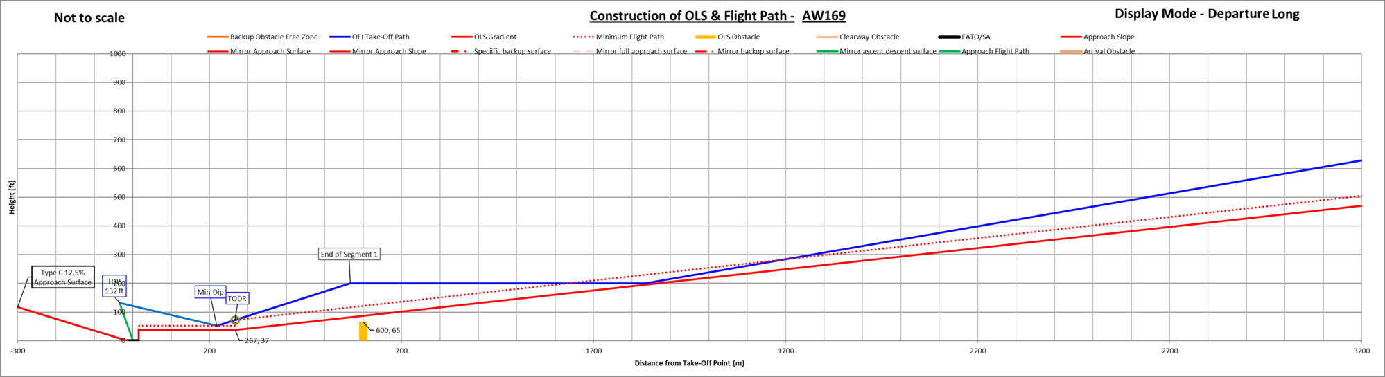
However, the aircraft is capable of climbing to 1000 ft by the pilot continuing the climb on the 2.5-minute power setting as shown:

So, to repeat my question, what in the RFM prevents the pilot from flying the profile in the second figure?
The accurate representation of AW 169 performance below shows that adherence to the profile puts (or is likely to put) the aircraft in conflict with the 4.5% obstacle limitation surface (OLS). This is due to limiting the first segment climb to 200 ft.
However, the aircraft is capable of climbing to 1000 ft by the pilot continuing the climb on the 2.5-minute power setting as shown:
So, to repeat my question, what in the RFM prevents the pilot from flying the profile in the second figure?
Joined: Jan 2024
Posts: 153
Likes: 90
From: Finland
If you are required to fly CAT A PC1, then you must fly a CAT A profile described in the RFM/OM. If a pilot modifies the profile, then the flight is no more operated with PC1.
To fly a PC1 profile, obstacle clearance must be assured, usually using pre-calculated plates. If required obstacle clearance is not assured, TDP and/or aircraft performance (weight) must be modified or another profile used.
That�s my understanding, but I�m happy to learn more.
To fly a PC1 profile, obstacle clearance must be assured, usually using pre-calculated plates. If required obstacle clearance is not assured, TDP and/or aircraft performance (weight) must be modified or another profile used.
That�s my understanding, but I�m happy to learn more.