


Light Helicopters and Tail Rotor Rolling Couple

Chaps,
Your physics is completely flawed!
Regardless of where you put the horizontal vector it remains the same.
The action is the drift caused by the horizontal vector from the TR.
The reaction to maintain equilibrium (i.e no drift) is from the main rotor and it reacts around the vertical centre of gravity.
Simple question - tell me where you get the extra energy to make it tilt further around the centre of gravity?
Answers on the back of a postage stamp please.
Last edited by RVDT; 5th Jun 2012 at 10:38.

AoTW - even with a teetering head helo and a TR that is above the MR hub, I don't agree that you will have a right roll as you always have to tilt the disc to the left to oppose the TR drift - I think the best you can expect is laterally level fuselage in that condition. The disc is 'flying' left and will tend to drag the fuselage with it.
My 'completely correct' statement was a result of too much celebrating the Jubilee last night and a somewhat fuzzy head this morning.
My 'completely correct' statement was a result of too much celebrating the Jubilee last night and a somewhat fuzzy head this morning.
Glad you had a good time, Crab!
I still think I'm right, as I can't see any other way to resolve the force diagram.
I admit it sounds a bit counter-intuitive, but if you put the forces at the appropriate vertical positions, look at the couples they form and see which way the torque from those couples would act, it seems to me they'll do as I pointed out before.
Yes, the MR anti-drift force must act left, and the TR drift force acts right, but if you reverse their vertical points of action the roll is also reversed. When they're acting in line (hubs at same height), no roll.
Weight can be said to act through the C of G, but that doesn't imply the aircraft must roll about it all the time, as some posters imply.
RVDT, the reaction from the main rotor, as you call it, is a force applied at the rotor head (for the teetering head case I was describing), not through the C of G.
Send return stamp, over! (All in good fun, though).
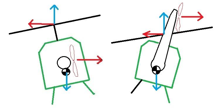
A couple of rough diagrams, maybe not enough colours for CFS but you get the idea.
If we're going to talk about physics, this is what you'd put up as a force diagram - the forces, and where they act.
The picture on the right is obviously the silly case where the tail rotor is mounted way above the rotor head, the one on the left the conventional setup. In both cases, two couples form in equilibrium.
An unopposed couple causes a roll, in these cases the MR and TR side forces. The roll will continue until the opposing couple is big enough, ie the one formed between MR thrust vertical component and weight. As the roll progresses, the vertical thrust line of those two forces splits until the moment arm between them is big enough so the opposing torque they create stops the roll.
I can't see it working any other way, but am happy to consider opposing arguments, postage stamp or otherwise.
Last edited by Arm out the window; 6th Jun 2012 at 03:37. Reason: To add text
AoTW - but the horizontal component of MR thrust will be large enough to oppose the TR thrust, even if the TR is very high since the aim is to counter TR drift so you just put more left cyclic in. Then, the horizontal forces cancel each other out and you are left with a level fuselage. It's like putting a fat kid nearer the fulcrum of a see-saw to balance a lighter kid further away. Apologies to any fat kids who may be offended
True, Crab, the magnitude of the opposing forces will be equal no matter where they are positioned vertically, but it's the relative vertical positions that produce the rolling couple.
When the main and tail rotor hubs are equal in height, there'll be no roll, but when the opposing forces are split vertically, there'll be a roll in the appropriate direction which will continue until the opposing couple (the weight/vertical MR thrust couple) grows big enough to counterbalance - when the C of G has been sufficiently displaced from under the head by the roll.
You only put in enough left cyclic to counter the tail rotor drift force, which is the same no matter what vertical position the tail rotor is at. So those forces are essentially fixed, but their by-product (which varies with relative vertical position) is a roll.
The fuselage will only be level when the side forces are at that co-height point. Anywhere else, there'll be a roll angle.
But we know that doesn't happen - for example when you push the nose down to transition to forward flight (thereby raising the TR) you don't get a roll to the right even with excessive amounts of nose down.
So somewhere along the line the physics is incomplete since the theory doesn't match the reality.
So somewhere along the line the physics is incomplete since the theory doesn't match the reality.
But we know that doesn't happen - for example when you push the nose down to transition to forward flight (thereby raising the TR) you don't get a roll to the right even with excessive amounts of nose down.
hence as Nick Lappos said in a previous post some 10 years ago, the placement of the T/R relative to the M/R head is only slight.
A force diagram is pretty straightforward, as are force couples. If we're having trouble with this idea, then does anyone have dramas with thrust line in a fixed wing, for example?
A high mounted engine with respect to the centre of pressure (drag wise, whatever the aerodynamicists call the point where drag is said to act, vertically speaking) will cause a nose-down pitch when power is added. If the engine is lower than that point, you'll get a pitch up. Same sort of thing.
Well, that's a dynamic situation with all sorts of stuff going on - collective, cyclic and pedal inputs all being made by looking out the front and reacting to a sight picture, inflow roll, flapback etc, so it's a fair bit different to a stable hover situation which is what the discussion was based on.
if your couples are correct the aircraft must roll right as the TR passes the height of the MR
The placement of the T/R relative to the M/R head has nothing to with the rolling force generated by the T/R.
Cheers all, we must look a bit like a bunch of old bearded blokes arguing about verses in the Koran or something.
Join Date: Dec 2008
Location: N/A
Posts: 845
Likes: 0
Received 0 Likes
on
0 Posts
Originally Posted by crab@
oTW - even with a teetering head helo and a TR that is above the MR hub, I don't agree that you will have a right roll as you always have to tilt the disc to the left to oppose the TR drift - I think the best you can expect is laterally level fuselage in that condition. The disc is 'flying' left and will tend to drag the fuselage with it.
In this example height of T/R wrt the disk is the only thing influencing the roll required to counter that 'mismatch'
The point is : you could measure the 'heights' of the horizontal components from the CoG - but the height of the CoG cancels out so it becomes the height of the T/R horizontal vector compared with the height of the plane in which the torque is delivered.
So a T/R hypothetically above the plane of the disk will lead to the counter intuitive roll direction... (in a teetering rotorhead)
Head coupling might modify that since to produce a M/R horizontal component which is equal and opposite to T/R thrust some roll moment from that will occur.
Last edited by Senior Pilot; 7th Jun 2012 at 09:44. Reason: Personal attack removed
Sounds like we're in agreeance, AnFI, though my aim is more to make sure I understand the balance of forces and moments clearly than to prove someone else wrong!
With a semi-rigid or rigid head, as you say, the leftward inclination of the rotor disc to provide the side force will also be associated with an anticlockwise torque applied to the mast head (as seen from the rear of the aircraft), which I think would increase the leftward roll angle a bit. Maybe!
With a semi-rigid or rigid head, as you say, the leftward inclination of the rotor disc to provide the side force will also be associated with an anticlockwise torque applied to the mast head (as seen from the rear of the aircraft), which I think would increase the leftward roll angle a bit. Maybe!
Whilst AoTW's physics seem correct, I can't find anything in any of my books to corroborate the theory - in most, such a situation isn't covered at all (including Prouty). The US Army manual shows the limit of TR roll to be a level fuselage on a teetering head helo (205) with a high placed TR with all other configurations giving left roll.
AoTW may be completely correct and this may be why there don't seem to be any helicopters designed this way yet there are lots of clever ways (offset rotor mast, modifications to the mixing unit etc) of trying to reduce the amount of TR roll to the left in 'normal' helicopters.
AoTW may be completely correct and this may be why there don't seem to be any helicopters designed this way yet there are lots of clever ways (offset rotor mast, modifications to the mixing unit etc) of trying to reduce the amount of TR roll to the left in 'normal' helicopters.
I have a lot of affection for the 205, the Huey being my first operational type, and it generally used to sit a bit nose up in the hover (MR hub a few feet above the level of the TR hub) but in the cruise the two would come back into line.
I don't know what the designers were after with the high-mounted tail rotor, maybe just to keep it out of the grass, but it would have mitigated the tail rotor roll somewhat no doubt. Even then it was almost always left skid low in the hover unless you had some strange loading going on or someone hanging off the hoist.
I think to get it any higher would be structurally impractical, bring the main rotor too close to the boom or have an infeasibly long upswept part on the rear of the boom, not to mention the weight penalty.
Happy days!
Last edited by Arm out the window; 7th Jun 2012 at 05:04.
Join Date: Dec 2008
Location: N/A
Posts: 845
Likes: 0
Received 0 Likes
on
0 Posts
The whole point about understanding Newton et al is that all of a sudden you don't need to learn each phenomenon from a text book. There's a framework from which other behaviors and characteristics are self evident. This understanding enables pilots to fly sympathetically.
The thought of you doing this in a Lynx:
from your position of lack of understanding highlights the need for tough airframes.
The thought of you doing this in a Lynx:
When performing loops or backflips where a maximum cyclic displacement and high rate of application is required, the amount of left cyclic required to keep the 'wings' level is quite noticeable.
Last edited by Senior Pilot; 7th Jun 2012 at 09:43. Reason: Personal attack removed
AoTW - the raising of the TR on the 205 will be to do with giving a useable range of Longitudinal C of G so that with a lot of troops in the back you don't have too much left roll as well as giving ground clearance at the back end.
Join Date: Jul 2010
Location: The American Steppe
Posts: 55
Likes: 0
Received 0 Likes
on
0 Posts
That's what I like about PPRuNe. You can learn so much here. Where I come from the Tail Rotor Rolling Couple is illegal in every state except Nevada, and there they make you pay extra for it.
AotW, the more I look at it the more I think you are right and one of the reasons we don't normally see this situation is that most teetering head helos (205, 206, R22) have the MR mounted very high on a long rotor mast so that the TR is very unlikely to ever get above the MR (except in extreme attitudes).
Now I don't know about the 205 but I vaguely seem to remember on a 206 that the MRGB is tilted slightly to the left to compensate for TR drift, possibly because the 205 had a raised TR boom but the 206 doesn't.
Who would be a helicopter designer?
Now I don't know about the 205 but I vaguely seem to remember on a 206 that the MRGB is tilted slightly to the left to compensate for TR drift, possibly because the 205 had a raised TR boom but the 206 doesn't.
Who would be a helicopter designer?
High TR
Aotw,
I suspect that you are correct re the UH-1 series designs and TR position. A huge factor for a tactical machine ( that is, keeping the tail rotor away from terra firma ), and the reason that the UH-60 has a tail wheel whose crash load design is the same as the mains.
With regard to the 205 shaft tilt, it is five degrees and is up a couple from the UH-1B which preceded. big improvement in drag at cruise vs the B model. I always thought that the reduced 2P vibration in the UH-1D/H was flapping related and for sure the flapping in a D/H at cruise ( and loaded ) was far lower that in the B. Maybe someone from Bell can comment and /or correct that supposition.
With regard to optimizing hover attitude, two models come to mind that employed lateral shaft tilt to accomplish that goal: The Sikorsky S-64 Skycrane and the Kaman UH-2 Seasprite. Both were successful in accomplishing a level hover, but there were other impacts on overall handling such that none of the modern designers ( from any OEM ) seem to think its worth it. Count me in that number.
After returning from flying a Cobra in Vietnem, Nick Lappos graduated second in his class at Georgia Tech: pay attention to his comments re free body diagrams.
Thanks,
John Dixson